2007 SUZUKI SWIFT CAN bus
[x] Cancel search: CAN busPage 198 of 1496
Downloaded from www.Manualslib.com manuals search engine 1A-148 Engine General Information and Diagnosis:
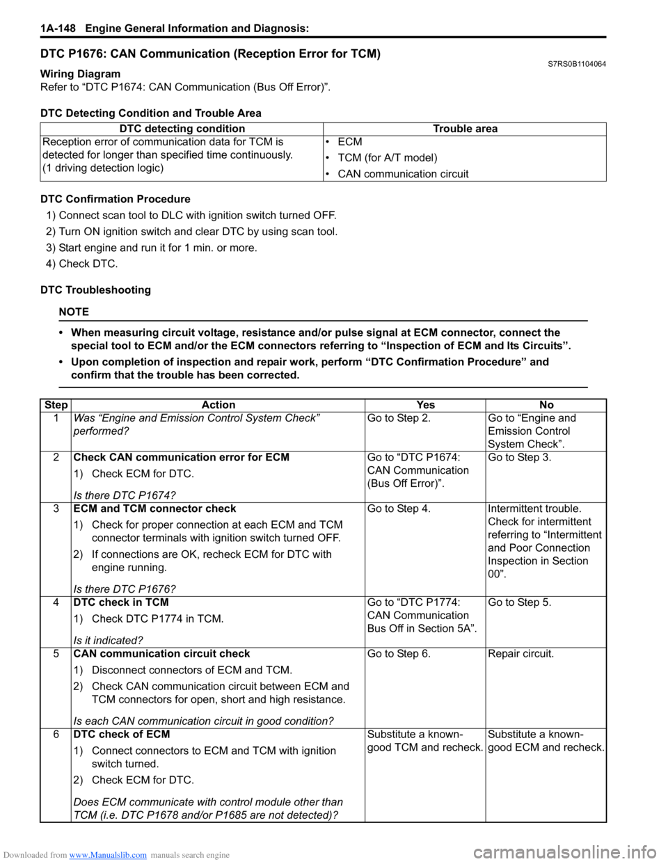
DTC P1676: CAN Communication (Reception Error for TCM)S7RS0B1104064
Wiring Diagram
Refer to “DTC P1674: CAN Communication (Bus Off Error)”.
DTC Detecting Condition and Trouble Area
DTC Confirmation Procedure1) Connect scan tool to DLC with ignition switch turned OFF.
2) Turn ON ignition switch and clear DTC by using scan tool.
3) Start engine and run it for 1 min. or more.
4) Check DTC.
DTC Troubleshooting
NOTE
• When measuring circuit voltage, resistance and/ or pulse signal at ECM connector, connect the
special tool to ECM and/or the ECM connectors re ferring to “Inspection of ECM and Its Circuits”.
• Upon completion of inspection and repair work, perform “DTC Confirmation Procedure” and confirm that the trouble has been corrected.
DTC detecting condition Trouble area
Reception error of communication data for TCM is
detected for longer than specified time continuously.
(1 driving detection logic) •ECM
• TCM (for A/T model)
• CAN communication circuit
Step
Action YesNo
1 Was “Engine and Emission Control System Check”
performed? Go to Step 2.
Go to “Engine and
Emission Control
System Check”.
2 Check CAN communication error for ECM
1) Check ECM for DTC.
Is there DTC P1674? Go to “DTC P1674:
CAN Communication
(Bus Off Error)”.
Go to Step 3.
3 ECM and TCM connector check
1) Check for proper connection at each ECM and TCM
connector terminals with ignition switch turned OFF.
2) If connections are OK, recheck ECM for DTC with engine running.
Is there DTC P1676? Go to Step 4.
Intermittent trouble.
Check for intermittent
referring to “Intermittent
and Poor Connection
Inspection in Section
00”.
4 DTC check in TCM
1) Check DTC P1774 in TCM.
Is it indicated? Go to “DTC P1774:
CAN Communication
Bus Off in Section 5A”.
Go to Step 5.
5 CAN communication circuit check
1) Disconnect connectors of ECM and TCM.
2) Check CAN communication circuit between ECM and
TCM connectors for open, short and high resistance.
Is each CAN communication circuit in good condition? Go to Step 6.
Repair circuit.
6 DTC check of ECM
1) Connect connectors to ECM and TCM with ignition
switch turned.
2) Check ECM for DTC.
Does ECM communicate with control module other than
TCM (i.e. DTC P1678 and/or P1685 are not detected)? Substitute a known-
good TCM and recheck.
Substitute a known-
good ECM and recheck.
Page 199 of 1496

Downloaded from www.Manualslib.com manuals search engine Engine General Information and Diagnosis: 1A-149
DTC P1678: CAN Communication (Reception Error for BCM)S7RS0B1104065
Wiring Diagram
Refer to “DTC P1674: CAN Communication (Bus Off Error)”.
DTC Detecting Condition and Trouble Area
DTC Confirmation Procedure1) Connect scan tool to DLC with ignition switch turned OFF.
2) Turn ON ignition switch and clear DTC by using scan tool.
3) Start engine and run it for 1 min. or more.
4) Check DTC.
DTC Troubleshooting
NOTE
• When measuring circuit voltage, resistance and/ or pulse signal at ECM connector, connect the
special tool to ECM and/or the ECM connectors re ferring to “Inspection of ECM and Its Circuits”.
• Upon completion of inspection and repair work, perform “DTC Confirmation Procedure” and confirm that the trouble has been corrected.
DTC detecting condition Trouble area
Reception error of communication data for BCM is
detected for longer than specified time continuously.
(1 driving detection logic but MIL does not light up) •ECM
• ABS/ESP®
control module
•BCM
• CAN communication circuit
Step Action YesNo
1 Was “Engine and Emission Control System Check”
performed? Go to Step 2.
Go to “Engine and
Emission Control
System Check”.
2 CAN communication error check for ECM
1) Check ECM for DTC.
Is there DTC P1674? Go to “DTC P1674:
CAN Communication
(Bus Off Error)”.
Go to Step 3.
3 ECM, ABS control module and BCM connector check
1) Check for proper connecti on at each ECM, ABS/ESP®
control module and BCM connector terminals with
ignition switch turned OFF.
2) If connections are OK, recheck ECM for DTC with engine running.
Is there DTC P1678? Go to Step 4.
Intermittent trouble.
Check for intermittent
referring to “Intermittent
and Poor Connection
Inspection in Section
00”.
4 DTC check in BCM
1) Check DTC U1073 in BCM.
Is it indicated? Go to “DTC U1073 (No.
1073): Control Module
Communication Bus Off
in Section 10B”.Go to Step 5.
5 DTC check of ABS/ESP ® control module
1) Check DTC U1073 in ABS/ESP ® control module.
Is it indicated? Go to “DTC U1073:
Control Module
Communication Bus Off
in Section 4E”.Go to Step 6.
Page 200 of 1496

Downloaded from www.Manualslib.com manuals search engine 1A-150 Engine General Information and Diagnosis:
DTC P1685: CAN Communication (Reception Error for ABS/ESP® Control Module)S7RS0B1104066
Wiring Diagram
Refer to “DTC P1674: CAN Communication (Bus Off Error)”
DTC detecting Condition and Trouble Area
DTC confirmation procedure
1) Connect scan tool to DLC with ignition switch turned OFF.
2) Turn ON ignition switch and clear DTC by using scan tool.
3) Start engine and run it for 1 min. or more.
4) Check DTC. 6
CAN communication circuit check
1) Turn ignition switch to OFF position.
2) Disconnect connectors fo rm ECM, BCM and ABS/ESP®
control modules.
3) Check CAN communication circuit for open, short or high resistance.
• Between ECM and ABS/ESP ® control module
• Between ECM and BCM
Is each CAN communication circuit in good condition? Go to Step 7. Repair circuit.
7 DTC check in ECM
1) Connect connectors to ECM, BCM and ABS/ESP ®
control module with ignition switch turned.
2) Check ECM for DTC.
Does ECM communicate with control module other than
BCM (i.e. DTC P1676 and/or DTC P1685 are not detected)? Substitute a known-
good BCM and recheck.
Substitute a known-
good ECM and recheck.
Step
Action YesNo
DTC detecting condition Trouble area
Reception error of communication data for ABS/ESP ®
control module is detected for longer than specified time
continuously.
(1 driving cycle detection logic) •ECM
• ABS/ESP®
control module
• CAN communication circuit
Page 201 of 1496
Downloaded from www.Manualslib.com manuals search engine Engine General Information and Diagnosis: 1A-151
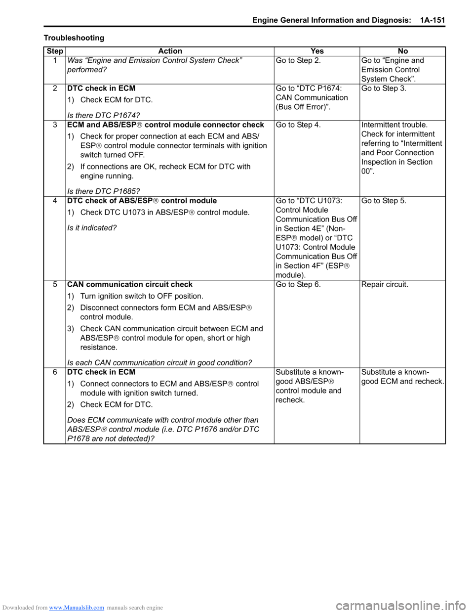
TroubleshootingStep Action Yes No 1 Was “Engine and Emission Control System Check”
performed? Go to Step 2. Go to “Engine and
Emission Control
System Check”.
2 DTC check in ECM
1) Check ECM for DTC.
Is there DTC P1674? Go to “DTC P1674:
CAN Communication
(Bus Off Error)”.
Go to Step 3.
3 ECM and ABS/ESP ® control module connector check
1) Check for proper connection at each ECM and ABS/ ESP® control module connector terminals with ignition
switch turned OFF.
2) If connections are OK, recheck ECM for DTC with engine running.
Is there DTC P1685? Go to Step 4.
Intermittent trouble.
Check for intermittent
referring to “Intermittent
and Poor Connection
Inspection in Section
00”.
4 DTC check of ABS/ESP ® control module
1) Check DTC U1073 in ABS/ESP ® control module.
Is it indicated? Go to “DTC U1073:
Control Module
Communication Bus Off
in Section 4E” (Non-
ESP®
model) or “DTC
U1073: Control Module
Communication Bus Off
in Section 4F” (ESP ®
module). Go to Step 5.
5 CAN communication circuit check
1) Turn ignition switch to OFF position.
2) Disconnect connector s form ECM and ABS/ESP ®
control module.
3) Check CAN communication circuit between ECM and ABS/ESP ® control module for open, short or high
resistance.
Is each CAN communication circuit in good condition? Go to Step 6.
Repair circuit.
6 DTC check in ECM
1) Connect connectors to ECM and ABS/ESP ® control
module with ignition switch turned.
2) Check ECM for DTC.
Does ECM communicate with control module other than
ABS/ESP
® control module (i.e. DTC P1676 and/or DTC
P1678 are not detected)? Substitute a known-
good ABS/ESP
®
control module and
recheck. Substitute a known-
good ECM and recheck.
Page 322 of 1496
Downloaded from www.Manualslib.com manuals search engine 1D-37 Engine Mechanical:
Valves and Cylinder Head Disassembly and
Assembly
S7RS0B1406025
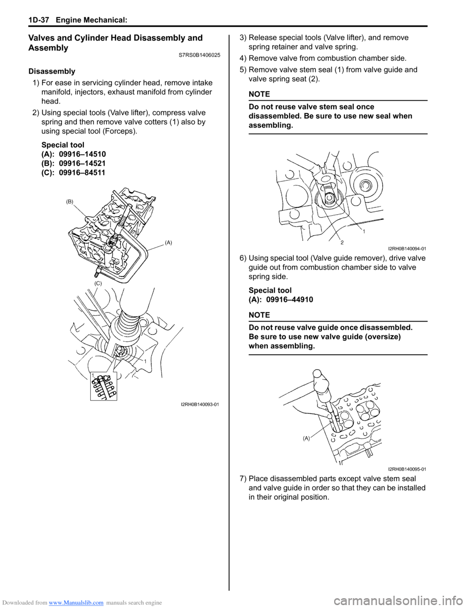
Disassembly1) For ease in servicing cylinder head, remove intake manifold, injectors, exhaust manifold from cylinder
head.
2) Using special tools (Val ve lifter), compress valve
spring and then remove valve cotters (1) also by
using special tool (Forceps).
Special tool
(A): 09916–14510
(B): 09916–14521
(C): 09916–84511 3) Release special tools (Valve lifter), and remove
spring retainer and valve spring.
4) Remove valve from combustion chamber side.
5) Remove valve stem seal (1) from valve guide and valve spring seat (2).
NOTE
Do not reuse valve stem seal once
disassembled. Be sure to use new seal when
assembling.
6) Using special tool (Valve guide remover), drive valve guide out from combustion chamber side to valve
spring side.
Special tool
(A): 09916–44910
NOTE
Do not reuse valve guide once disassembled.
Be sure to use new va lve guide (oversize)
when assembling.
7) Place disassembled parts except valve stem seal
and valve guide in order so that they can be installed
in their original position.
I2RH0B140093-01
I2RH0B140094-01
I2RH0B140095-01
Page 447 of 1496
Downloaded from www.Manualslib.com manuals search engine Front Suspension: 2B-14
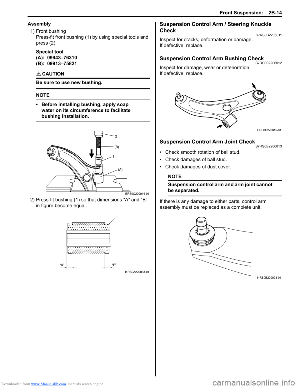
Assembly1) Front bushing Press-fit front bushing (1) by using special tools and
press (2).
Special tool
(A): 09943–76310
(B): 09913–75821
CAUTION!
Be sure to use new bushing.
NOTE
• Before installing bushing, apply soap water on its circumference to facilitate
bushing installation.
2) Press-fit bushing (1) so that dimensions “A” and “B” in figure become equal.
Suspension Control Arm / Steering Knuckle
Check
S7RS0B2206011
Inspect for cracks, deformation or damage.
If defective, replace.
Suspension Control Arm Bushing CheckS7RS0B2206012
Inspect for damage, wear or deterioration.
If defective, replace.
Suspension Control Arm Joint CheckS7RS0B2206013
• Check smooth rotation of ball stud.
• Check damages of ball stud.
• Check damages of dust cover.
NOTE
Suspension control a rm and arm joint cannot
be separated.
If there is any damage to either parts, control arm
assembly must be replaced as a complete unit.
1 2
(A)
(B)
I6RS0C220014-01
I4RS0A220033-01
I6RS0C220015-01
I4RS0B220023-01
Page 452 of 1496

Downloaded from www.Manualslib.com manuals search engine 2B-19 Front Suspension:
13) Install suspension control arm referring to
“Suspension Control Arm / Bushing Removal and
Installation”.
14) Connect couplers of torque sensor and P/S motor.
15) Connect tie-rod ends to knuckles (right & left) and then install cotter pins referring to “Tie-Rod End
Removal and Installa tion in Section 6C”.
16) Be sure that steering wheel and brake discs (right & left) are all straight-ahead position and then insert
steering lower shaft (5) into steering pinion shaft (3)
with matching marks (4).
17) Tighten steering shaft joint lower bolt (1) and upper bolt (2) to specified torque (Lower side first and then
upper side).
Tightening torque
Steering shaft joint bolt (a): 25 N·m (2.5 kgf-m,
18.5 lb-ft)
18) Install both wheels and tighten wheel bolts to specified torque.
Tightening torque
Wheel bolt: 85 N·m (8.5 kgf-m, 61.5 lb-ft)
19) Lower hoist.
20) Check toe setting. Adjust as required refer to “Front Wheel Alignment Inspection and Adjustment”.
Front Suspension Frame CheckS7RS0B2206016
Inspect for cracks, deformation or damage.
If defective, replace.
Front Stabilizer Bar, Bushing and/or Joint
Check
S7RS0B2206017
Stabilizer Bar
Inspect for damage or deformation.
If defective, replace.
Stabilizer Bushing
Inspect for damage, wear or deterioration.
If defective, replace.
Stabilizer Joint
1) Check for smooth rotation.
2) Check damages of ball stud.
3) Check damages of dust cover.
NOTE
Stabilizer joint (1) cannot be disassembled.
If there is any damage to either parts, stabilizer joint
assembly must be replaced as a complete unit.
Front Suspension Fasteners CheckS7RS0B2206018
Check each bolt and nut fastening suspension parts for
tightness. Tighten loose one, if any, to specified torque,
referring to “Front Suspension Construction”.
5
4
1, (a)
3
2, (a)
1, (a)
5
I4RS0B630016-01
I4RS0A220054-01
I4RS0A220052-01
I4RS0A220056-01
1
I4RH01220007-01
Page 458 of 1496
Downloaded from www.Manualslib.com manuals search engine 2C-4 Rear Suspension:
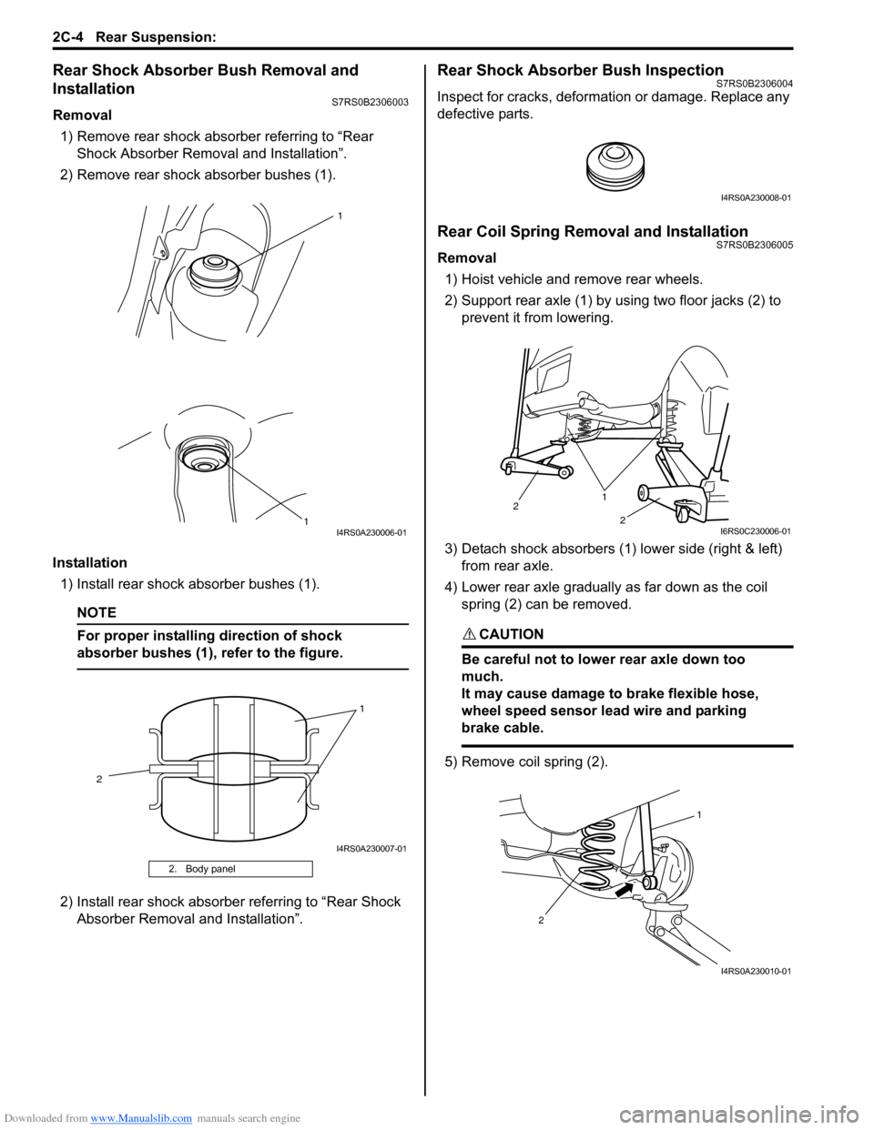
Rear Shock Absorber Bush Removal and
Installation
S7RS0B2306003
Removal1) Remove rear shock absorber referring to “Rear Shock Absorber Remova l and Installation”.
2) Remove rear shock absorber bushes (1).
Installation 1) Install rear shock absorber bushes (1).
NOTE
For proper installing direction of shock
absorber bushes (1), refer to the figure.
2) Install rear shock absorber referring to “Rear Shock Absorber Removal and Installation”.
Rear Shock Absorber Bush InspectionS7RS0B2306004
Inspect for cracks, deformation or damage. Replace any
defective parts.
Rear Coil Spring Removal and InstallationS7RS0B2306005
Removal
1) Hoist vehicle and remove rear wheels.
2) Support rear axle (1) by using two floor jacks (2) to prevent it from lowering.
3) Detach shock absorbers (1) lower side (right & left) from rear axle.
4) Lower rear axle gradually as far down as the coil spring (2) can be removed.
CAUTION!
Be careful not to lowe r rear axle down too
much.
It may cause damage to brake flexible hose,
wheel speed sensor lead wire and parking
brake cable.
5) Remove coil spring (2).
2. Body panel
1
1
I4RS0A230006-01
1
2
I4RS0A230007-01
I4RS0A230008-01
1
2
2
I6RS0C230006-01
1
2
I4RS0A230010-01