2007 SUZUKI SWIFT Oul
[x] Cancel search: OulPage 791 of 1496

Downloaded from www.Manualslib.com manuals search engine Automatic Transmission/Transaxle: 5A-147
3) Install new differential side oil seal to transaxle case by using special tools.
Special tool
(A): 09924–74510
(B): 09944–88220
Differential side oil seal installing depth
“a”: 3.8 – 4.8 mm (0.15 – 0.19 in.)
4) Apply grease to oil seal lip. : Grease 99000–25030 (SUZUKI Super Grease C)
Automatic Transaxle Unit Inspection and
Adjustment
S7RS0B5106059
Inspection
Brake discs
Dry and inspect them for pitting, burn flaking, significant
wear, glazing, cracking, charring and chips or metal
particles imbedded in lining.
If discs show any of the ab ove conditions, replacement
is required.
NOTE
• If disc lining is exfoliated or discolored, replace all discs.
• Before assembling new discs, soak them in A/T fluid for at least two hours.
Brake separator plates and retaining plates
Dry plates and check for discol oration. If plate surface is
smooth and even color smear is indicated, plate should
be reused. If severe heat spot discoloration or surface
scuffing is indicated, plate must be replaced.
Brake return spring subassembly
Measure free length of each brake return spring
subassembly.
Evidence of extreme heat or burning in the area of clutch
may have caused springs to take heat set and would
require their replacement.
Free length of 1st & reverse brake return spring
subassembly
“a”: 21.71 mm (0.855 in.)
Free length of 2nd brake return spring subassembly
“a”: 15.85 mm (0.624 in.)
NOTE
• Do not apply excessive force when measuring spring free length.
• Perform measurement at several points.
I2RH0B510252-01
I2RH01510147-01
I2RH0B510253-01
I2RH0B510173-01
Page 796 of 1496

Downloaded from www.Manualslib.com manuals search engine 5A-152 Automatic Transmission/Transaxle:
12) Install 1st and reverse brake plate snap ring so that its both ends would be positioned in correct locations
as shown in figure.
13) Using special tools, meas ure 1st and reverse brake
piston stroke when compressed air (400 – 800 kPa,
4 – 8 kg/cm
2, 57 – 113 psi) is brown through oil hole.
Special tool
(A): 09900–20607
(B): 09900–20701
(C): 09952–06020
1st and reverse brake piston stroke
Standard: 0.791 – 1.489 mm (0.0311 – 0.0586 in.) 14) Install reduction drive gear (1) to transaxle case (3)
by using special tools and hydraulic press.
CAUTION!
• Do not use transaxle case as groundwork to press fit reduction drive gear.
• Do not give load more than 20 kN (2000 kg, 4410 lb) with hydraulic press. Otherwise, it
may result in damaging reduction drive
gear bearing.
NOTE
When replacing reduction drive gear, replace
it together with reduction driven gear as a
set.
Special tool
(A): 09951–18210
(B): 09944–78210
15) Install parking lock pawl (1) and spring (2). Apply A/T fluid to parking lock pawl sh aft, then insert it into
transaxle case.
[A]: Correct [B]: Incorrect
I2RH0B510268-01
I2RH0B510269-01
2. Stand that can slightly lift transaxle case.
I2RH0B510270-01
I2RH0B510271-01
Page 797 of 1496

Downloaded from www.Manualslib.com manuals search engine Automatic Transmission/Transaxle: 5A-153
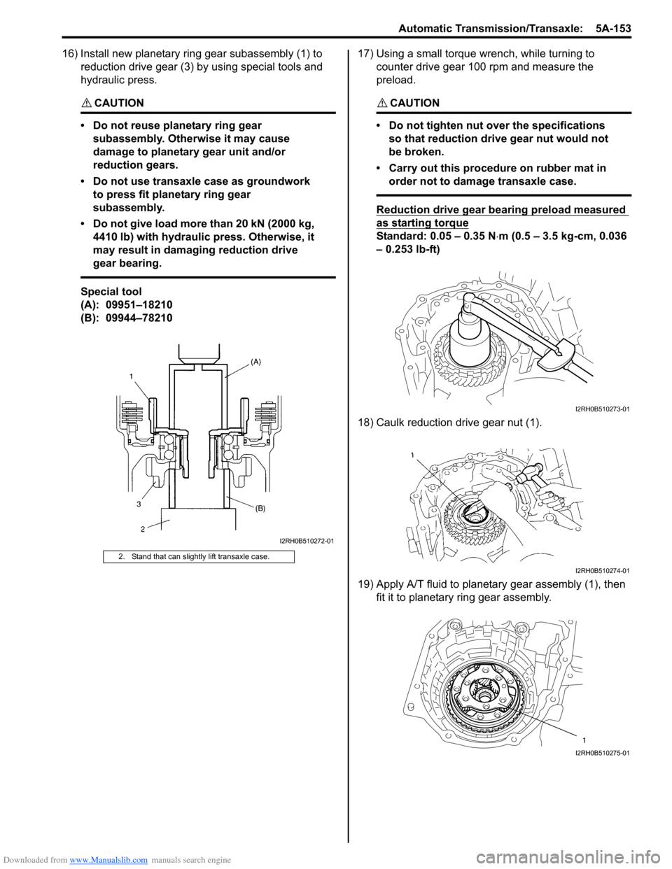
16) Install new planetary ring gear subassembly (1) to reduction drive gear (3) by using special tools and
hydraulic press.
CAUTION!
• Do not reuse planetary ring gear subassembly. Otherwise it may cause
damage to planetary gear unit and/or
reduction gears.
• Do not use transaxle case as groundwork to press fit planetary ring gear
subassembly.
• Do not give load more than 20 kN (2000 kg, 4410 lb) with hydraulic press. Otherwise, it
may result in damaging reduction drive
gear bearing.
Special tool
(A): 09951–18210
(B): 09944–78210 17) Using a small torque
wrench, while turning to
counter drive gear 100 rpm and measure the
preload.
CAUTION!
• Do not tighten nut over the specifications so that reduction drive gear nut would not
be broken.
• Carry out this procedure on rubber mat in order not to damage transaxle case.
Reduction drive gear bearing preload measured
as starting torque
Standard: 0.05 – 0.35 N ⋅m (0.5 – 3.5 kg-cm, 0.036
– 0.253 lb-ft)
18) Caulk reduction drive gear nut (1).
19) Apply A/T fluid to planetary gear assembly (1), then fit it to planetary ring gear assembly.
2. Stand that can slightly lift transaxle case.
I2RH0B510272-01
I2RH0B510273-01
I2RH0B510274-01
1
I2RH0B510275-01
Page 810 of 1496

Downloaded from www.Manualslib.com manuals search engine 5A-166 Automatic Transmission/Transaxle:
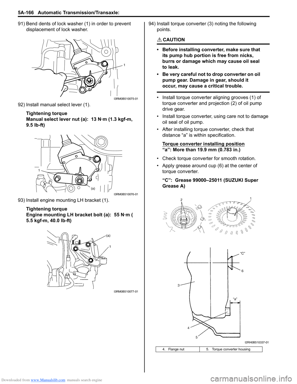
91) Bend dents of lock washer (1) in order to prevent displacement of lock washer.
92) Install manual select lever (1). Tightening torque
Manual select lever nut (a): 13 N·m (1.3 kgf-m,
9.5 lb-ft)
93) Install engine mounting LH bracket (1). Tightening torque
Engine mounting LH bracket bolt (a): 55 N·m (
5.5 kgf-m, 40.0 lb-ft) 94) Install torque converter (3) noting the following
points.
CAUTION!
• Before installing converter, make sure that its pump hub portion is free from nicks,
burrs or damage which may cause oil seal
to leak.
• Be very careful not to drop converter on oil pump gear. Damage in gear, should it
occur, may cause a critical trouble.
• Install torque converter aligning grooves (1) of torque converter and projection (2) of oil pump
drive gear.
• Install torque converter, using care not to damage oil seal of oil pump.
• After installing torque converter, check that distance “a” is within specification.
Torque converter installing position
“a”: More than 19.9 mm (0.783 in.)
• Check torque converter for smooth rotation.
• Apply grease around cup (6) at the center of torque converter.
“C”: Grease 99000–25011 (SUZUKI Super
Grease A)
1
I3RM0B510075-01
1
(a)
I3RM0B510076-01
I3RM0B510077-01
4. Flange nut 5. Torque converter housing
I2RH0B510337-01
Page 824 of 1496

Downloaded from www.Manualslib.com manuals search engine 5B-10 Manual Transmission/Transaxle:
16) Remove engine under covers.
17) Support transaxle with transmission jack.
18) Remove transaxle to engine bolts and nut of lower side.
19) Remove engine left mounting (1) with bracket (2).
20) Remove engine rear mounting bracket bolts (1).
21) Remove other attached parts from transaxle, if any.
22) Pull transaxle so as to disconnect input shaft from clutch disc, and then lower it. Remounting
CAUTION!
• Care should be taken not to scratch oil
seal lip with drive shaft while raising
transaxle.
• Do not hit drive shaft joint with hammer when installing it into differential gear.
Reverse dismounting procedure for remounting noting
the following.
• Tighten each bolts and nuts to specified torque referring to “Manual Transaxle Unit Components”.
• Set each clamp for wiring securely.
• Fill transaxle oil referring to “Manual Transaxle Oil
Change”.
• Fill coolant referring to “Cooling System Flush and
Refill in Section 1F”.
• Install hook (1) and ground cable (2) at specified position as shown in figure.
• Connect battery and check function of engine, clutch
and transaxle.
1
2
I4RS0A520021-01
1
I4RS0A520022-01
3. Transaxle side cover 4. Transaxle left case
90
1
2 3
4
I4RS0A520023-01
Page 828 of 1496

Downloaded from www.Manualslib.com manuals search engine 5B-14 Manual Transmission/Transaxle:
Fifth Gear Disassembly and AssemblyS7RS0B5206014
Disassembly1) Remove cover bolts and take off transaxle side cover (1).
CAUTION!
Care should be taken not to distort side cover
when it is removed from left case.
2) Using snap ring pliers, remove circlip (1).
3) Remove 5th shift fork bolt (2).
4) Remove gear shift fork (3), synchronizer sleeve &
hub assembly (4), synchron izer levers, synchronizer
ring and input shaft 5th gear (5) all together. Use
gear puller for removal if spline fitting of hub is tight. 5) Unfasten caulking of countershaft nut (2), install
input shaft 5th gear (1) and special tool to stop
rotation of shafts, and then remove countershaft nut
(2).
Special tool
(A): 09927–76060
6) Remove input shaft 5th gear, needle bearing and then countershaft 5th gear (1). Gear puller (2) would
be necessary if spline fitting of countershaft 5th gear
is tight.
11. Sensor cap 34. Washer
12. Oil gutter bolt : Apply thread lock 99000-32110 to all around thread part of bolt. 35. Side bearing retainer
13. Left case plate bolts : Apply thread lock 99000-32110 to all around thread part of bolt. 36. O-ring
14. Sensor cap bolt 37. Oil seal
: Apply grease 99000-25011 to oil seal lip.
15. Side cover bolts 38. Outer race
16. Transaxle case bolts 39. Breather hose
17. 5th speed synchronizer ring 40. Side bearing retainer bolt
18. 5th speed synchronizer lever : 23 N⋅m (2.3 kgf-m, 17.0 lb-ft)
19. 5th speed synchronizer sleeve & hub : 21 N⋅m (2.1 kgf-m, 15.5 lb-ft)
20. Circlip :10 N⋅m (1.0 kgf-m, 7.5 lb-ft)
21. Bearing set shim : 100 N⋅m (10.0 kgf-m, 72.5 lb-ft)
22. Countershaft 5th gear : Do not reuse.
23. Countershaft nut : After tightening nut to specified torque, caulk nut securely. : Apply transaxle oil.
I4RS0A520027-01
342
1
5
I4RS0A520028-01
1(A)
2
I3RM0B521014-01
I4RS0A520041-01
Page 848 of 1496

Downloaded from www.Manualslib.com manuals search engine 5B-34 Manual Transmission/Transaxle:
Assembly
Judging from abnormality noted before disassembly and
what is found through visual check of component parts
after disassembly, prepare replacing parts and proceed
to reassembly. Make sure that all parts are clean.
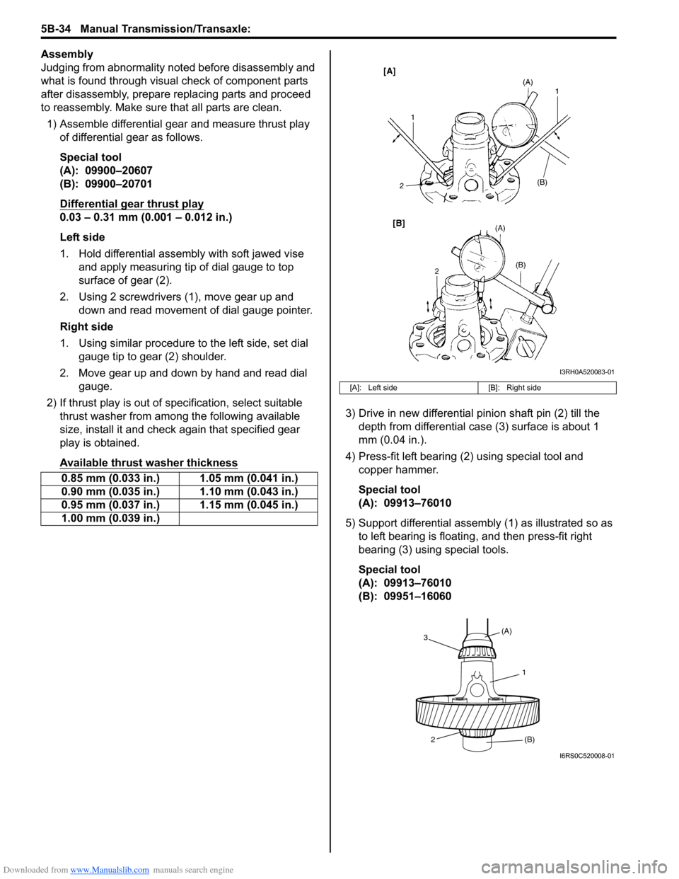
1) Assemble differential gear and measure thrust play
of differential gear as follows.
Special tool
(A): 09900–20607
(B): 09900–20701
Differential gear thrust play
0.03 – 0.31 mm (0.001 – 0.012 in.)
Left side
1. Hold differential assembly with soft jawed vise and apply measuring tip of dial gauge to top
surface of gear (2).
2. Using 2 screwdrivers (1), move gear up and down and read movement of dial gauge pointer.
Right side
1. Using similar procedure to the left side, set dial gauge tip to gear (2) shoulder.
2. Move gear up and down by hand and read dial gauge.
2) If thrust play is out of sp ecification, select suitable
thrust washer from among the following available
size, install it and check again that specified gear
play is obtained.
Available thrust washer thickness
3) Drive in new differential pinion shaft pin (2) till the depth from differential case (3) surface is about 1
mm (0.04 in.).
4) Press-fit left bearing (2) using special tool and copper hammer.
Special tool
(A): 09913–76010
5) Support differential assembly (1) as illustrated so as to left bearing is floating , and then press-fit right
bearing (3) using special tools.
Special tool
(A): 09913–76010
(B): 09951–16060
0.85 mm (0.033 in.) 1.05 mm (0.041 in.)
0.90 mm (0.035 in.) 1.10 mm (0.043 in.)
0.95 mm (0.037 in.) 1.15 mm (0.045 in.)
1.00 mm (0.039 in.)
[A]: Left side
[B]: Right side
I3RH0A520083-01
1
(A)
3
2 (B)
I6RS0C520008-01
Page 855 of 1496

Downloaded from www.Manualslib.com manuals search engine Clutch: 5C-3
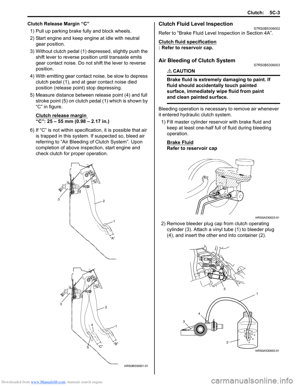
Clutch Release Margin “C”1) Pull up parking brake fully and block wheels.
2) Start engine and keep engine at idle with neutral gear position.
3) Without clutch pedal (1) dep ressed, slightly push the
shift lever to re verse position until transaxle emits
gear contact noise. Do not shift the lever to reverse
position.
4) With emitting gear contact noise, be slow to depress clutch pedal (1), and at gear contact noise died
position (release point) stop depressing.
5) Measure distance between release point (4) and full stroke point (5) on clutch pedal (1) which is shown by
“C” in figure.
Clutch release margin
“C”: 25 – 55 mm (0.98 – 2.17 in.)
6) If “C” is not within specificat ion, it is possible that air
is trapped in this system. If suspected so, bleed air
referring to “Air Bleeding of Clutch System”. Upon
completion of above inspection, start engine and
check clutch for proper operation.
Clutch Fluid Level InspectionS7RS0B5306002
Refer to “Brake Fluid Level Inspection in Section 4A”.
Clutch fluid specification
: Refer to reservoir cap.
Air Bleeding of Clutch SystemS7RS0B5306003
CAUTION!
Brake fluid is extremely damaging to paint. If
fluid should accidentally touch painted
surface, immediately wipe fluid from paint
and clean painted surface.
Bleeding operation is necessary to remove air whenever
it entered hydraulic clutch system.
1) Fill master cylinder reservoir with brake fluid and keep at least one-half full of fluid during bleeding
operation.
Brake Fluid
Refer to reservoir cap
2) Remove bleeder plug cap from clutch operating cylinder (3). Attach a vinyl tube (1) to bleeder plug
(4), and insert the other end into container (2).
2
1
“A”
3
2
1
3
“B”
“C”
4
5
I4RS0B530001-01
I4RS0A530023-01
3 4 1
2
3
I4RS0A530003-01