2007 SUZUKI SWIFT Oul
[x] Cancel search: OulPage 710 of 1496
Downloaded from www.Manualslib.com manuals search engine 5A-66 Automatic Transmission/Transaxle:
DTC P0974 / P0977: Shift Solenoid “A” / Shift Solenoid “B” Control Circuit HighS7RS0B5104034
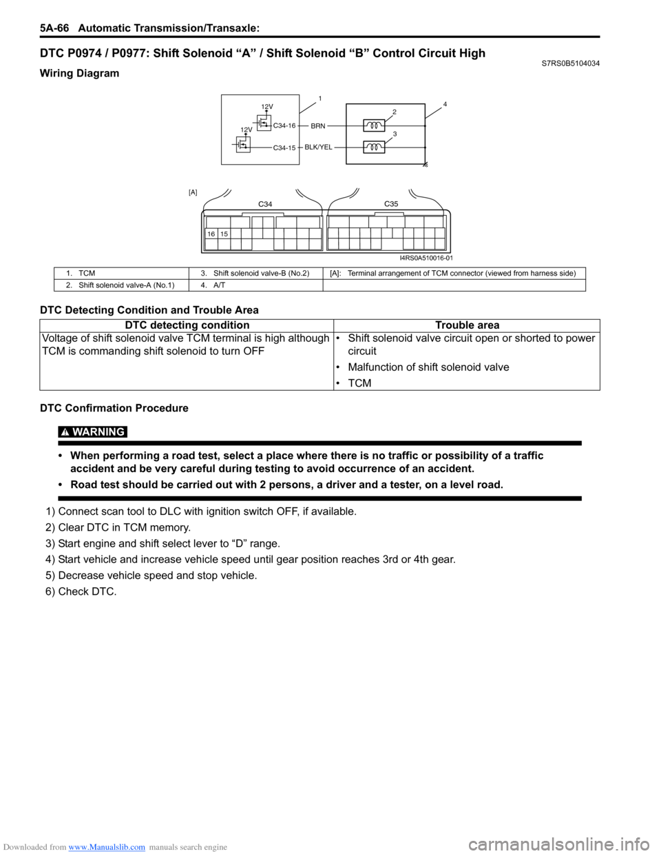
Wiring Diagram
DTC Detecting Condition and Trouble Area
DTC Confirmation Procedure
WARNING!
• When performing a road test, select a place where there is no traffic or possibility of a traffic
accident and be very careful during testing to avoid occurrence of an accident.
• Road test should be carried out with 2 persons, a driver and a tester, on a level road.
1) Connect scan tool to DLC with ig nition switch OFF, if available.
2) Clear DTC in TCM memory.
3) Start engine and shift select lever to “D” range.
4) Start vehicle and increase vehicle speed until gear position reaches 3rd or 4th gear.
5) Decrease vehicle sp eed and stop vehicle.
6) Check DTC.
1. TCM 3. Shift solenoid valve-B (No.2) [A]: Terminal arra ngement of TCM connector (viewed from harness side)
2. Shift solenoid valve-A (No.1) 4. A/T
DTC detecting condition Trouble area
Voltage of shift solenoid valve TCM terminal is high although
TCM is commanding shift solenoid to turn OFF • Shift solenoid valve circuit open or shorted to power
circuit
• Malfunction of shift solenoid valve
•TCM
12V
12VBRNC34-16
C34-15BLK/YEL
41
2
3
16 15
C34C35
[A]
I4RS0A510016-01
Page 712 of 1496
Downloaded from www.Manualslib.com manuals search engine 5A-68 Automatic Transmission/Transaxle:
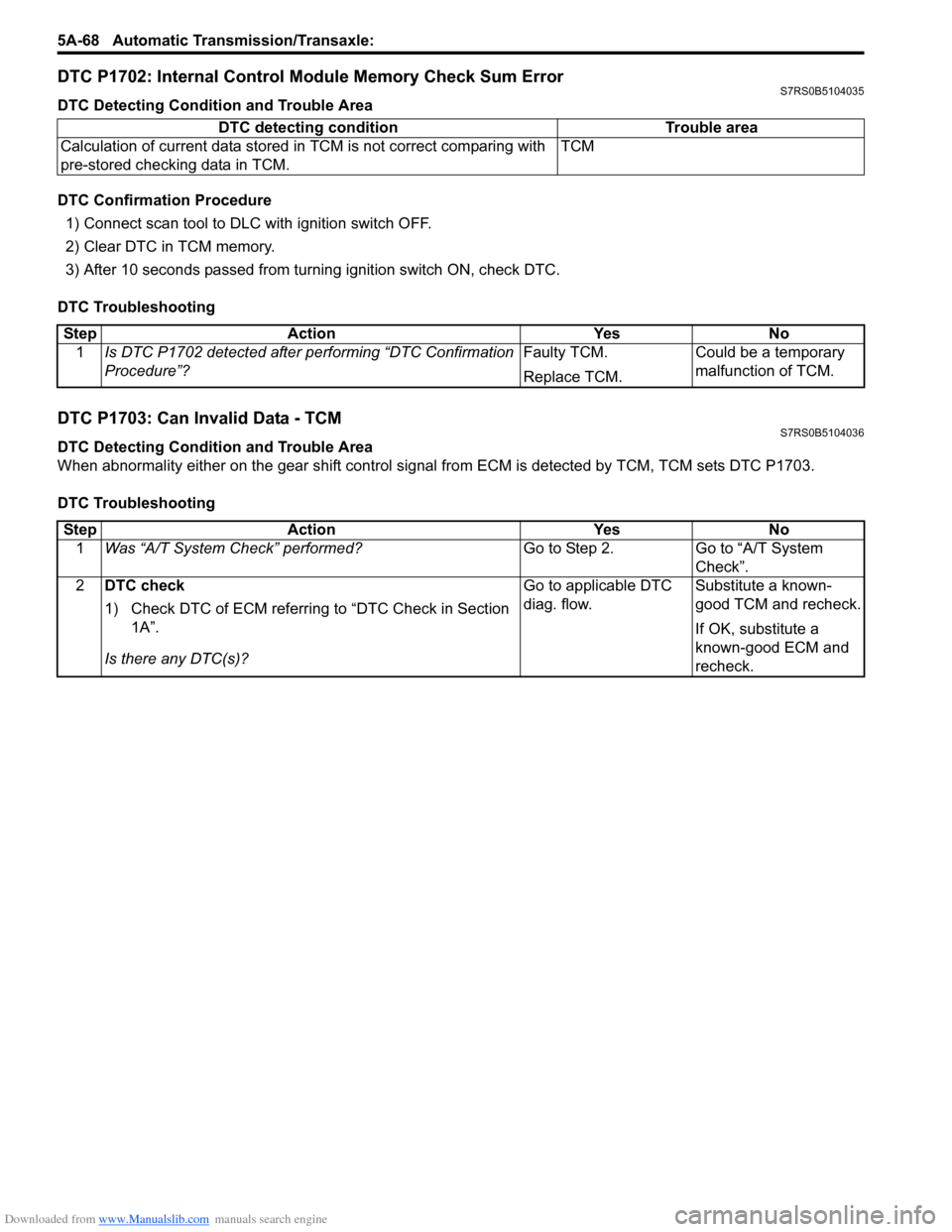
DTC P1702: Internal Control Module Memory Check Sum ErrorS7RS0B5104035
DTC Detecting Condition and Trouble Area
DTC Confirmation Procedure
1) Connect scan tool to DLC with ignition switch OFF.
2) Clear DTC in TCM memory.
3) After 10 seconds passed from turning ignition switch ON, check DTC.
DTC Troubleshooting
DTC P1703: Can Invalid Data - TCMS7RS0B5104036
DTC Detecting Condition and Trouble Area
When abnormality either on the gear shift control signal from ECM is detected by TCM, TCM sets DTC P1703.
DTC Troubleshooting DTC detecting condition Trouble area
Calculation of current data stored in TCM is not correct comparing with
pre-stored checking data in TCM. TCM
Step
Action YesNo
1 Is DTC P1702 detected after performing “DTC Confirmation
Procedure”? Faulty TCM.
Replace TCM.Could be a temporary
malfunction of TCM.
Step
Action YesNo
1 Was “A/T System Check” performed? Go to Step 2.Go to “A/T System
Check”.
2 DTC check
1) Check DTC of ECM referring to “DTC Check in Section
1A”.
Is there any DTC(s)? Go to applicable DTC
diag. flow.
Substitute a known-
good TCM and recheck.
If OK, substitute a
known-good ECM and
recheck.
Page 719 of 1496
Downloaded from www.Manualslib.com manuals search engine Automatic Transmission/Transaxle: 5A-75
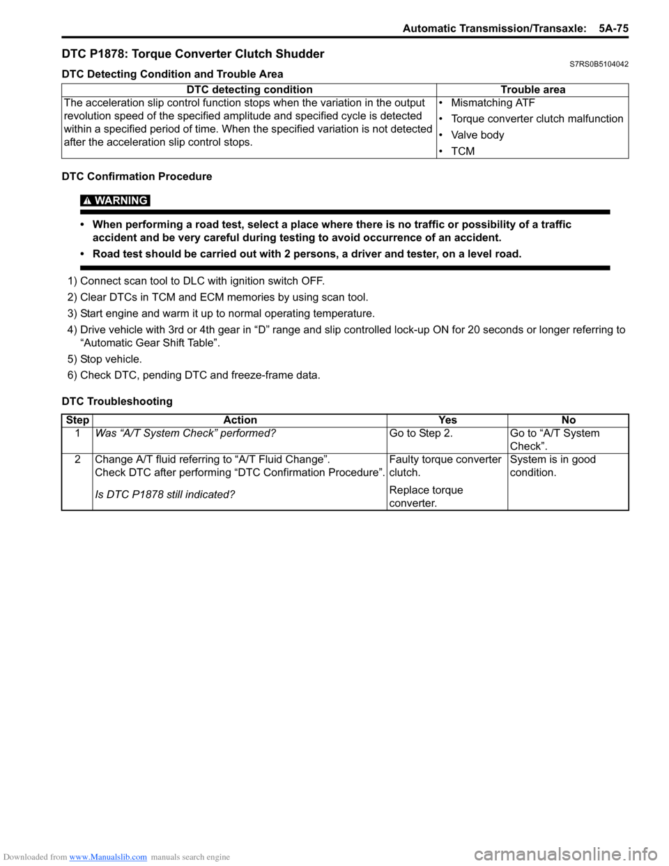
DTC P1878: Torque Converter Clutch ShudderS7RS0B5104042
DTC Detecting Condition and Trouble Area
DTC Confirmation Procedure
WARNING!
• When performing a road test, select a place where there is no traffic or possibility of a traffic accident and be very careful during testing to avoid occurrence of an accident.
• Road test should be carried out with 2 persons, a driver and tester, on a level road.
1) Connect scan tool to DLC with ignition switch OFF.
2) Clear DTCs in TCM and ECM memories by using scan tool.
3) Start engine and warm it up to normal operating temperature.
4) Drive vehicle with 3rd or 4th gear in “D” range and slip c ontrolled lock-up ON for 20 seconds or longer referring to
“Automatic Gear Shift Table”.
5) Stop vehicle.
6) Check DTC, pending DTC and freeze-frame data.
DTC Troubleshooting DTC detecting condition
Trouble area
The acceleration slip control function stops when the variation in the output
revolution speed of the specified amp litude and specified cycle is detected
within a specified period of time. When t he specified variation is not detected
after the acceleration slip control stops. • Mismatching ATF
• Torque converter clutch malfunction
• Valve body
•TCM
Step
Action YesNo
1 Was “A/T System Check” performed? Go to Step 2.Go to “A/T System
Check”.
2 Change A/T fluid referring to “A/T Fluid Change”. Check DTC after performing “DTC Confirmation Procedure”.
Is DTC P1878 still indicated? Faulty torque converter
clutch.
Replace torque
converter.System is in good
condition.
Page 722 of 1496

Downloaded from www.Manualslib.com manuals search engine 5A-78 Automatic Transmission/Transaxle:
DTC P2763: Torque Converter Clutch Pressure Control Solenoid Control Circuit HighS7RS0B5104043
Wiring Diagram
DTC Detecting Condition and Trouble Area
DTC Confirmation Procedure
WARNING!
• When performing a road test, select a place where there is no traffic or possibility of a traffic
accident and be very careful during testing to avoid occurrence of an accident.
• Road test should be carried out with 2 persons, a driver and a tester, on a level road.
1) Connect scan tool to DLC with ig nition switch OFF, if available.
2) Clear DTC in TCM memory.
3) Start engine.
4) Keep engine running at idle speed in “P” range for 10 seconds or more.
5) Check DTC.
DTC Troubleshooting
1. TCM 3. A/T
2. TCC lock-up pressure control solenoid valve [A]: Terminal arrangement of TCM connector (viewed from harness side)
DTC detecting conditionTrouble area
Voltage of TCC lock-up pressure control solenoid valve TCM
terminal is high although TCM is commanding TCC lock-up
pressure control sole noid to turn OFF. • TCC lock-up pressure contro
l solenoid valve circuit
shorted to ground
• Malfunction of TCC lock-up pressure control solenoid valve
•TCM
12V
C34-5
C34-3
WHT/BLU
WHT/BLK
3
1
2
53
C34C35
[A]
I4RS0A510019-01
Step
Action YesNo
1 Was “A/T System Check” performed? Go to Step 2.Go to “A/T System
Check”.
Page 724 of 1496

Downloaded from www.Manualslib.com manuals search engine 5A-80 Automatic Transmission/Transaxle:
DTC P2764: Torque Converter Clutch Circuit Pressure Control Solenoid Control Circuit LowS7RS0B5104044
Wiring Diagram
DTC Detecting Condition and Trouble Area
DTC Confirmation Procedure
WARNING!
• When performing a road test, select a place where there is no traffic or possibility of a traffic
accident and be very careful during testing to avoid occurrence of an accident.
• Road test should be carried out with 2 persons, a driver and a tester, on a level road.
1) Connect scan tool to DLC with ig nition switch OFF, if available.
2) Clear DTC in TCM memory.
3) Start engine.
4) Keep engine running at idle speed in “P” range for 20 seconds or more.
5) Check DTC.
DTC Troubleshooting
1. TCM 3. A/T
2. TCC pressure control solenoid valve [A]: Terminal arrangement of TCM connector (viewed from harness side)
DTC detecting condition Trouble area
Voltage of TCC lock-up pressure control solenoid valve TCM
terminal is low although TCM is commanding TCC lock-up
pressure control sole noid to turn ON. • TCC lock-up pressure contro
l solenoid valve circuit
shorted to ground
• Malfunction of TCC lock-up pressure control solenoid valve
•TCM
12V
C34-5
C34-3
WHT/BLU
WHT/BLK
3
1
2
53
C34C35
[A]
I4RS0A510019-01
Step
Action YesNo
1 Was “A/T System Check” performed? Go to Step 2.Go to “A/T System
Check”.
Page 733 of 1496
Downloaded from www.Manualslib.com manuals search engine Automatic Transmission/Transaxle: 5A-89
A/T Fluid Level CheckS7RS0B5106002
CAUTION!
Do not use any fluid other than the specified
ATF. Use of any fluid other than the specified
ATF may cause juddering or some other
faulty condition to occur.
Level Check at Normal Operating (Hot) Temperature
– Hot Check1) Drive vehicle so that A/T fluid temperature reach the
normal operating temperature (70 – 80 °C (158 –
176 °F)).
2) Stop vehicle with engine running and place it level.
3) With select lever at “P” range, apply parking brake and place chocks against wheels.
4) Keep engine idling and shift selector slowly to “L” and back to “P” position.
5) With engine idling, pull out fluid level gauge, wipe it off with a clean cloth and put it back into place.
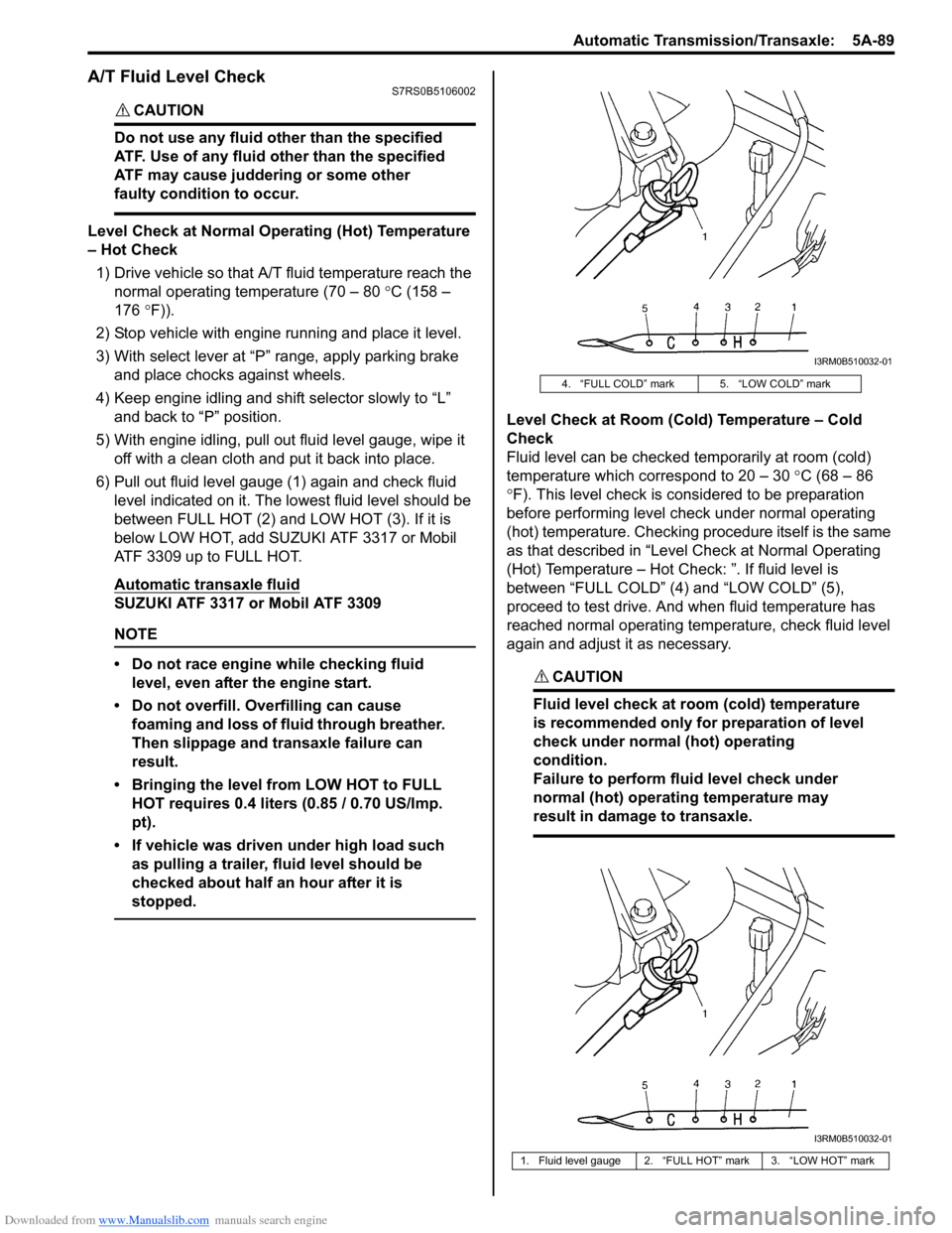
6) Pull out fluid level gauge (1) again and check fluid level indicated on it. The lo west fluid level should be
between FULL HOT (2) and LOW HOT (3). If it is
below LOW HOT, add SUZUKI ATF 3317 or Mobil
ATF 3309 up to FULL HOT.
Automatic transaxle fluid
SUZUKI ATF 3317 or Mobil ATF 3309
NOTE
• Do not race engine while checking fluid level, even after the engine start.
• Do not overfill. Overfilling can cause foaming and loss of fluid through breather.
Then slippage and transaxle failure can
result.
• Bringing the level from LOW HOT to FULL HOT requires 0.4 liters (0.85 / 0.70 US/Imp.
pt).
• If vehicle was driven under high load such as pulling a trailer, fluid level should be
checked about half an hour after it is
stopped.
Level Check at Room (Cold) Temperature – Cold
Check
Fluid level can be checked temporarily at room (cold)
temperature which correspond to 20 – 30 °C (68 – 86
° F). This level check is considered to be preparation
before performing level check under normal operating
(hot) temperature. Checking procedure itself is the same
as that described in “Level Check at Normal Operating
(Hot) Temperature – Hot Check: ”. If fluid level is
between “FULL COLD” (4) and “LOW COLD” (5),
proceed to test drive. And when fluid temperature has
reached normal operating temp erature, check fluid level
again and adjust it as necessary.
CAUTION!
Fluid level check at room (cold) temperature
is recommended only for preparation of level
check under normal (hot) operating
condition.
Failure to perform fluid level check under
normal (hot) operating temperature may
result in damage to transaxle.
4. “FULL COLD” mark 5. “LOW COLD” mark
1. Fluid level gauge 2. “FULL HOT” mark 3. “LOW HOT” mark
I3RM0B510032-01
I3RM0B510032-01
Page 737 of 1496
Downloaded from www.Manualslib.com manuals search engine Automatic Transmission/Transaxle: 5A-93
Select Cable AdjustmentS7RS0B5106013
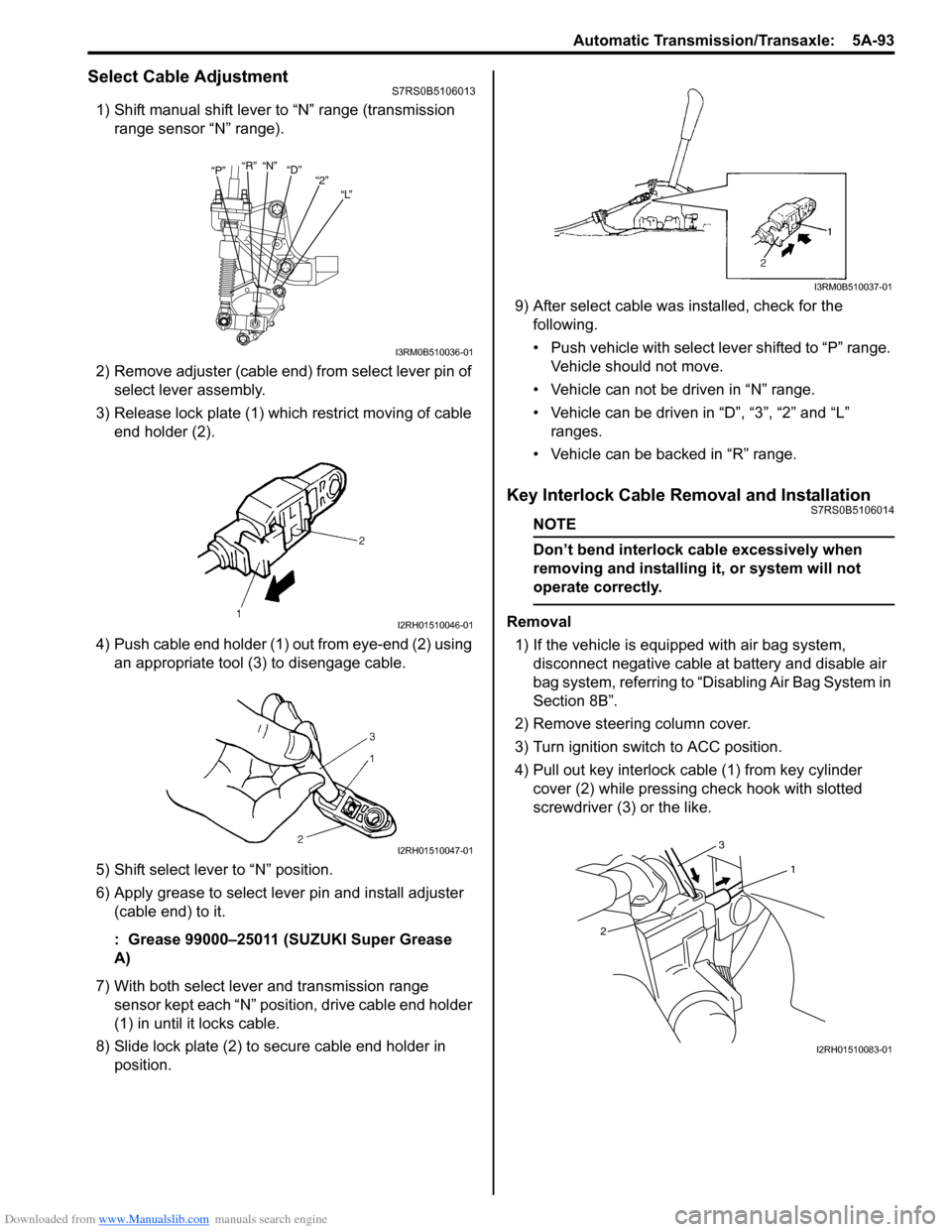
1) Shift manual shift lever to “N” range (transmission range sensor “N” range).
2) Remove adjuster (cable end) from select lever pin of select lever assembly.
3) Release lock plate (1) which restrict moving of cable end holder (2).
4) Push cable end holder (1) out from eye-end (2) using an appropriate tool (3) to disengage cable.
5) Shift select lever to “N” position.
6) Apply grease to select lever pin and install adjuster (cable end) to it.
: Grease 99000–25011 (SUZUKI Super Grease
A)
7) With both select lever and transmission range sensor kept each “N” position, drive cable end holder
(1) in until it locks cable.
8) Slide lock plate (2) to secure cable end holder in position. 9) After select cable was
installed, check for the
following.
• Push vehicle with select lever shifted to “P” range. Vehicle should not move.
• Vehicle can not be driven in “N” range.
• Vehicle can be driven in “D”, “3”, “2” and “L” ranges.
• Vehicle can be backed in “R” range.
Key Interlock Cable Removal and InstallationS7RS0B5106014
NOTE
Don’t bend interlock cable excessively when
removing and installing it, or system will not
operate correctly.
Removal
1) If the vehicle is equipped with air bag system, disconnect negative cable at battery and disable air
bag system, referring to “Disabling Air Bag System in
Section 8B”.
2) Remove steering column cover.
3) Turn ignition switch to ACC position.
4) Pull out key interlock cable (1) from key cylinder cover (2) while pressing check hook with slotted
screwdriver (3) or the like.
“P” “R”
“N”
“D”
“2”
“L”
I3RM0B510036-01
I2RH01510046-01
I2RH01510047-01
I3RM0B510037-01
1
2 3
I2RH01510083-01
Page 746 of 1496
Downloaded from www.Manualslib.com manuals search engine 5A-102 Automatic Transmission/Transaxle:
Operation Check
Check pressure control solenoid valves (Pressure
control solenoid and TCC pressure control solenoid)
operation in the either manner of the following.
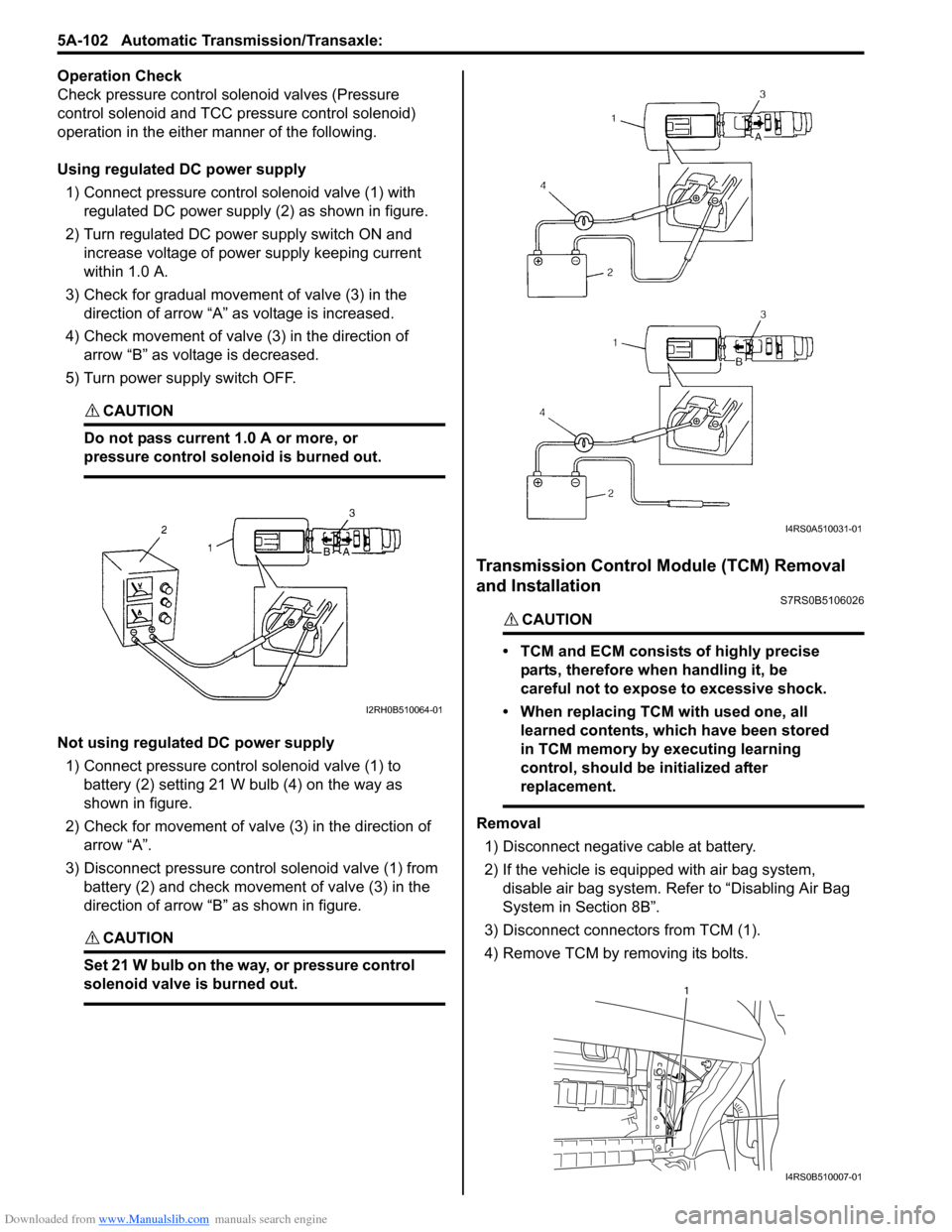
Using regulated DC power supply
1) Connect pressure contro l solenoid valve (1) with
regulated DC power supply (2) as shown in figure.
2) Turn regulated DC power supply switch ON and increase voltage of power supply keeping current
within 1.0 A.
3) Check for gradual movement of valve (3) in the direction of arrow “A” as voltage is increased.
4) Check movement of valve (3) in the direction of arrow “B” as voltage is decreased.
5) Turn power supply switch OFF.
CAUTION!
Do not pass current 1.0 A or more, or
pressure control solenoid is burned out.
Not using regulated DC power supply 1) Connect pressure control solenoid valve (1) to battery (2) setting 21 W bulb (4) on the way as
shown in figure.
2) Check for movement of valve (3) in the direction of arrow “A”.
3) Disconnect pressure control solenoid valve (1) from battery (2) and check movement of valve (3) in the
direction of arrow “B” as shown in figure.
CAUTION!
Set 21 W bulb on the way, or pressure control
solenoid valve is burned out.
Transmission Control Module (TCM) Removal
and Installation
S7RS0B5106026
CAUTION!
• TCM and ECM consists of highly precise
parts, therefore when handling it, be
careful not to expose to excessive shock.
• When replacing TCM with used one, all learned contents, which have been stored
in TCM memory by executing learning
control, should be initialized after
replacement.
Removal
1) Disconnect negative cable at battery.
2) If the vehicle is equipped with air bag system, disable air bag system. Refer to “Disabling Air Bag
System in Section 8B”.
3) Disconnect connectors from TCM (1).
4) Remove TCM by removing its bolts.
I2RH0B510064-01
I4RS0A510031-01
1
I4RS0B510007-01