2007 SUZUKI SWIFT pressure
[x] Cancel search: pressurePage 387 of 1496

Downloaded from www.Manualslib.com manuals search engine Fuel System: 1G-12
Fuel Tank Inlet Valve InspectionS7RS0B1706012
WARNING!
Before starting the following procedure, be
sure to observe “Precautions on Fuel System
Service” in order to reduce the risk or fire
and personal injury.
Check fuel tank inlet valve for the following.
If any damage or malfunction is found, replace.
•Damage
• Smooth opening and closing
Fuel Tank Removal and InstallationS7RS0B1706013
WARNING!
Before starting the following procedure, be
sure to observe “Precautions on Fuel System
Service” in order to reduce the risk or fire
and personal injury.
Removal1) Relieve fuel pressure in fuel feed line according to
“Fuel Pressure Relief Procedure”.
2) Disconnect negative cable at battery.
3) Hoist vehicle.
4) Remove exhaust center pipe.
5) Disconnect fuel filler hose and breather hose from
filler neck referring to “Fue l Tank Inlet Valve Removal
and Installation”.
6) Due to absence of fuel tank drain plug, drain fuel tank by pumping fuel out through fuel tank filler.
Use hand operated pump device to drain fuel tank.
CAUTION!
• Do not force pump hose into fuel tank, or pump hose may damage fuel tank inlet
valve.
• Never store fuel in an open container due to possibility of fire or explosion.
7) Disconnect fuel pipe joint and fuel hoses (1) from fuel pipes (2) referring to “Fuel Hose Disconnecting
and Reconnecting”.
8) Support fuel tank (1) with jack (2) and remove its mounting bolts.
9) Lower fuel tank a little as to disconnect wire harness at connector (1) and ground wire (2), then remove
fuel tank.
I2RH0B170019-01
12
I4RS0A170008-01
12
I4RS0A170009-01
1
2
I6RS0C170005-02
Page 389 of 1496

Downloaded from www.Manualslib.com manuals search engine Fuel System: 1G-14
Fuel Tank Purging ProcedureS7RS0B1706015
WARNING!
• Before starting the following procedure, be sure to observe “Precautions on Fuel
System Service” in order to reduce the risk
or fire and personal injury.
• This purging procedure will not remove all fuel vapor.
Do not attempt any repair on tank using
heat of flame as an explosion resulting in
personal injury could occur.
CAUTION!
Never remain water in fu el tank after washing,
or fuel tank inside will get corrosion.
The following procedure are used for purging fuel tank.
1) After removing fuel tank, remove all hoses, pipes and fuel pump assembly from fuel tank.
2) Drain all remaining fuel from tank.
3) Place fuel tank to flushing area.
4) Fill tank with warm water or tap water, and agitate
vigorously and drain. Repeat this washing until
inside of tank is clean. Replace tank if its inside is
rusty.
5) Completely flush out rema ining water after washing.
Fuel Pump On-Vehicle InspectionS7RS0B1706016
WARNING!
Before starting the following procedure, be
sure to observe “Precautions on Fuel System
Service” in order to reduce the risk or fire
and personal injury.
NOTE
The fuel pressure regulator is incorporated
with the fuel pump assembly so individual
inspection of it is impossible.
1) Remove filler cap and turn ON ignition switch (2).
Then fuel pump operating sound should be heard
from fuel filler (1) for about 2 seconds and stop. Be
sure to reinstall fuel filler cap after checking.
If the check result is not satisfactory, go to “Fuel
Pump and Its Circuit Check in Section 1A”. 2) Turn OFF ignition switch and leave over 10 minutes
as it is.
3) Fuel pressure should be felt at fuel feed hose (1) for about 2 seconds after ignition switch ON.
If fuel pressure is not felt, go to “Fuel Pressure
Check in Section 1A”.
Fuel Pump Assembly Removal and InstallationS7RS0B1706017
WARNING!
Before starting the following procedure, be
sure to observe “Precautions on Fuel System
Service” in order to reduce the risk or fire
and personal injury.
Removal
1) Remove fuel tank from vehicle. Refer to “Fuel Tank Removal and Installation”.
2) Disconnect fuel feed pipe (1) from fuel pump assembly (2) referring to “Fuel Hose Disconnecting
and Reconnecting”.
IVSY01170013-01
1I3RM0A170019-01
1
2
I6RS0C170008-02
Page 391 of 1496

Downloaded from www.Manualslib.com manuals search engine Fuel System: 1G-16
Removal1) Remove fuel pump assembly from fuel tank referring to “Fuel Pump Assembly Removal and Installation”.
2) Disconnect main fuel level sensor connector (3).
3) With pressing snap-fit part (2), remove main fuel level sensor (1) by sliding it in the arrow direction as
shown in figure.
Installation
Reverse removal procedure for installation.Fuel Pump InspectionS7RS0B1706019
• Check fuel pump assembly for damage.
• Check fuel suction filter for evidence of dirt and contamination. If present, replace or clean and check
for presence of dirt in fuel tank.
• For electrical circuit, refer to “Fuel Pressure Check in Section 1A”.
• For inspection of main fuel level sensor (1), refer to “Fuel Level Sensor Inspection in Section 9C”.
Specifications
Tightening Torque SpecificationsS7RS0B1707001
NOTE
The specified tightening torque is also described in the following.
“Fuel System Components”
“Fuel Hose Disconnecting and Reconnecting”
Reference:
For the tightening torque of fastener not specified in this section, refer to “Fasteners Information in Section 0A”.
1
21
3
I5RS0D170006-031
I5RS0D170008-01
Fastening part
Tightening torque
Note
N ⋅mkgf-mlb-ft
Fuel delivery pipe bolt 25 2.5 18.0 �)
Ground wire bolt 11 1.1 8.0 �)
Fuel tank bolt 45 4.5 33.0 �)
Fuel filler hose clamp 2 0.2 1.5 �)
Fuel pump assembly bolt 11 1.1 8.0 �)
Page 392 of 1496

Downloaded from www.Manualslib.com manuals search engine 1G-17 Fuel System:
Special Tools and Equipment
Special ToolS7RS0B1708001
09912–5761009912–58421
Injector checking tool plate Checking tool set
�) This kit includes the
following items. 1. Tool body
and washer, 2. Body plug, 3.
Body attachment-1, 4.
Holder, 5. Return hose and
clamp, 6. Body attachment-2
and washer, 7. Hose
attachment-1, 8. Hose
attachment-2�)
09912–58432 09912–58442
Fuel pressure gauge hose Fuel pressure gauge
This tool is included in fuel
pressure gauge set (09912-
58413). �) This tool is included in fuel
pressure gauge set (09912-
58413).
�)
09912–58490 09919–47020
3-way joint & hose Quick joint remover
�)�)
09930–88530 SUZUKI scan tool
Injector test lead —
�) This kit includes following
items. 1. Tech 2, 2. PCMCIA
card, 3. DLC cable, 4. SAE
16/19 adapter, 5. Cigarette
cable, 6. DLC loop back
adapter, 7. Battery power
cable, 8. RS232 cable, 9.
RS232 adapter, 10. RS232
loop back connector, 11.
Storage case, 12.�)
Page 417 of 1496

Downloaded from www.Manualslib.com manuals search engine Charging System: 1J-7
With Charging Equipment
CAUTION!
When jump starting engine with charging
equipment, be sure equipment used is 12-
volt and negative ground. Do not use 24-volt
charging equipment. Using such equipment
can cause serious damage to electrical
system or electronic parts.
Battery Dismounting and RemountingS7RS0B1A06002
WARNING!
When handling battery, following safety
precautions should be followed:
• Hydrogen gas is produced by battery. A flame or spark near battery may cause the
gas to ignite.
• Battery fluid is highly acidic. Avoid spilling on clothing or other fabric. Any spilled
electrolyte should be flushed with large
quantity of water and cleaned immediately.
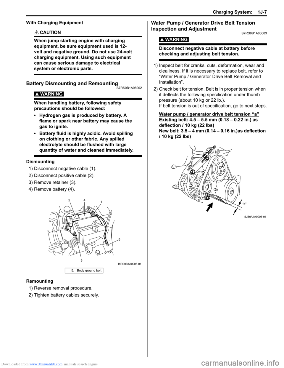
Dismounting
1) Disconnect negative cable (1).
2) Disconnect positive cable (2).
3) Remove retainer (3).
4) Remove battery (4).
Remounting 1) Reverse removal procedure.
2) Tighten battery cables securely.
Water Pump / Generator Drive Belt Tension
Inspection and Adjustment
S7RS0B1A06003
WARNING!
Disconnect negative cable at battery before
checking and adjusting belt tension.
1) Inspect belt for cranks, cuts, deformation, wear and clealiness. If it is necessary to replace belt, refer to
“Water Pump / Generator Drive Belt Removal and
Installation”.
2) Check belt for tension. Belt is in proper tension when it deflects the following specification under thumb
pressure (about 10 kg or 22 lb.).
If belt tension is out of spec ification, go to next steps.
Water pump / generator drive belt tension
“a”
Existing belt: 4.5 – 5.5 mm (0.18 – 0.22 in.) as
deflection / 10 kg (22 lbs)
New belt: 3.5 – 4 mm (0.14 – 0.16 in.)as deflection
/ 10 kg (22 lbs)
5. Body ground bolt
1
3 5
2
4
I4RS0B1A0006-01
“a”
I5JB0A1A0008-01
Page 432 of 1496

Downloaded from www.Manualslib.com manuals search engine 2A-1 Suspension General Diagnosis:
Suspension
Suspension General Diagnosis
Diagnostic Information and Procedures
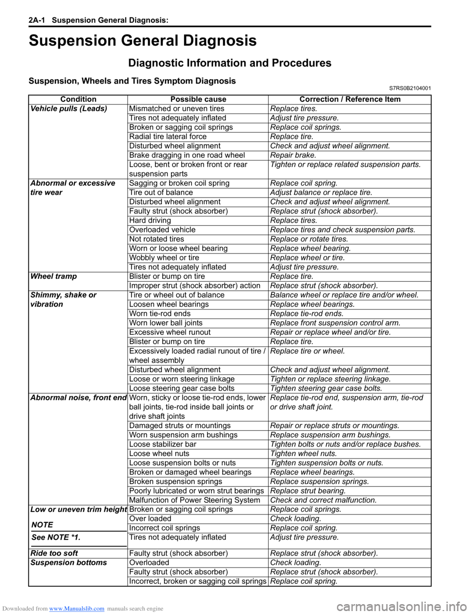
Suspension, Wheels and Tires Symptom DiagnosisS7RS0B2104001
ConditionPossible cause Correction / Reference Item
Vehicle pulls (Leads) Mismatched or uneven tires Replace tires.
Tires not adequately inflated Adjust tire pressure.
Broken or sagging coil springs Replace coil springs.
Radial tire lateral force Replace tire.
Disturbed wheel alignment Check and adjust wheel alignment.
Brake dragging in one road wheel Repair brake.
Loose, bent or broken front or rear
suspension parts Tighten or replace related suspension parts.
Abnormal or excessive
tire wear Sagging or broken coil spring
Replace coil spring.
Tire out of balance Adjust balance or replace tire.
Disturbed wheel alignment Check and adjust wheel alignment.
Faulty strut (shock absorber) Replace strut (shock absorber).
Hard driving Replace tires.
Overloaded vehicle Replace tires and check suspension parts.
Not rotated tires Replace or rotate tires.
Worn or loose wheel bearing Replace wheel bearing.
Wobbly wheel or tire Replace wheel or tire.
Tires not adequately inflated Adjust tire pressure.
Wheel tramp Blister or bump on tire Replace tire.
Improper strut (shock absorber) action Replace strut (shock absorber).
Shimmy, shake or
vibration Tire or wheel out of balance
Balance wheel or replace tire and/or wheel.
Loosen wheel bearings Replace wheel bearings.
Worn tie-rod ends Replace tie-rod ends.
Worn lower ball joints Replace front suspension control arm.
Excessive wheel runout Repair or replace wheel and/or tire.
Blister or bump on tire Replace tire.
Excessively loaded radial runout of tire /
wheel assembly Replace tire or wheel.
Disturbed wheel alignment Check and adjust wheel alignment.
Loose or worn steering linkage Tighten or replace steering linkage.
Loose steering gear case bolts Tighten steering gear case bolts.
Abnormal noise, front end Worn, sticky or loose tie-rod ends, lower
ball joints, tie-rod in side ball joints or
drive shaft joints Replace tie-rod end, su
spension arm, tie-rod
or drive shaft joint.
Damaged struts or mountings Repair or replace struts or mountings.
Worn suspension arm bushings Replace suspension arm bushings.
Loose stabilizer bar Tighten bolts or nuts and/or replace bushes.
Loose wheel nuts Tighten wheel nuts.
Loose suspension bolts or nuts Tighten suspension bolts or nuts.
Broken or damaged wheel bearings Replace wheel bearings.
Broken suspension springs Replace suspension springs.
Poorly lubricated or worn strut bearings Replace strut bearing.
Malfunction of Power Steering System Check and correct malfunction.
Low or uneven trim height
NOTE
See NOTE *1.
Broken or sagging coil springs Replace coil springs.
Over loaded Check loading.
Incorrect coil springs Replace coil spring.
Tires not adequately inflated Adjust tire pressure.
Ride too soft Faulty strut (shock absorber) Replace strut (shock absorber).
Suspension bottoms Overloaded Check loading.
Faulty strut (shock absorber) Replace strut (shock absorber).
Incorrect, broken or sagging coil springs Replace coil spring.
Page 435 of 1496

Downloaded from www.Manualslib.com manuals search engine Front Suspension: 2B-2
Front Wheel Alignment ConstructionS7RS0B2201002
Among factors for front wheel alignment, only toe setting
can be adjusted. Camber and caster are not adjustable.
Therefore, should camber or caster be out of
specification due to the damage caused by hazardous
road conditions or collision, whether the damage is in
body or in suspension should be determined and
damaged body should be repaired or damaged
suspension should be replaced.
Preliminary Checks Prior to Adjustment Front Wheel
Alignment
Steering and vibration complaints are not always the
result of improper wheel alignment. An additional item to
be checked is the possibility of tire lead due to worn or
improperly manufactured tires. “Lead” is the vehicle
deviation from a straight path on a level road without
hand pressure on the steering wheel. Refer to “Radial
Tire Lead / Pull Description in Section 2D” in order to
determine if the vehicle has a tire lead problem. Before
making any adjustment affecting wheel alignment, the
following checks and inspections should be made to
ensure correctness of alignment readings and alignment
adjustments:
• Check all tires for proper inflation pressures and approximately the same tread wear. • Check for loose of ball join
ts. Check tie-rod ends; if
excessive looseness is noted, it must be corrected
before adjusting.
• Check for run-out of wheels and tires.
• Check vehicle trim heights; if it is out of limit and a
correction is needed, it must be done before adjusting
toe.
• Check for loose of suspension control arms.
• Check for loose or missin g stabilizer bar attachments.
• Consideration must be given to excess loads, such as
tool boxes. If this excess load is normally carried in
vehicle, it should remain in vehicle during alignment
checks.
• Consider condition of equipment being used to check alignment and follow manufa cturer’s instructions.
• Regardless of equipment used to check alignment, vehicle must be placed on a level surface.
NOTE
To prevent possible incorrect reading of toe,
camber or caster, vehicle front and rear end
must be moved up and down a few times
before inspection.
Repair Instructions
Front Wheel Alignment Inspection and
Adjustment
S7RS0B2206001
Toe Inspection and Adjustment
Preparation for toe inspection and adjustment.
• Place vehicle in unloaded state on level surface.
• Set steering wheel in straight state.
• Check that inflation pressure of each tire is adjusted properly and wheel is free from deflection.
• Check that each suspension part is free from bend, dent, wear or damage in any other form.
• Check that ground clearance at the right and left is just about the same.
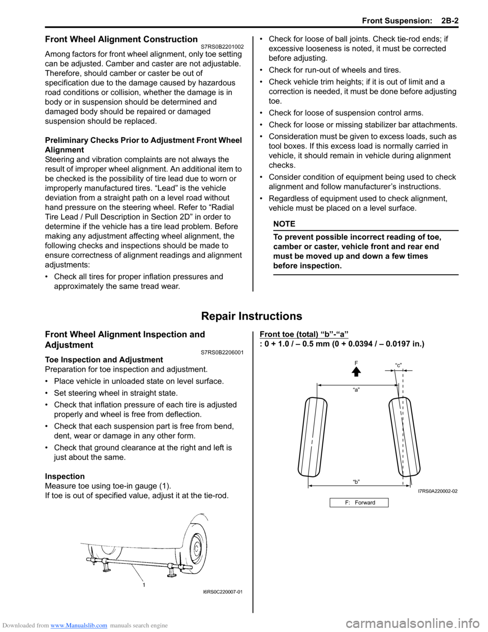
Inspection
Measure toe using toe-in gauge (1).
If toe is out of specified value, adjust it at the tie-rod. Front toe (total) “b”-“a”
: 0 + 1.0 / – 0.5 mm (0 + 0.0394 / – 0.0197 in.)
I6RS0C220007-01
F: Forward
“a”
“c”
“b” F
I7RS0A220002-02
Page 440 of 1496

Downloaded from www.Manualslib.com manuals search engine 2B-7 Front Suspension:
3) Install bump stopper onto strut rod. For installing
direction, refer to the figure in “Front Suspension
Construction”.
4) Pull strut rod as far up as possible and use care not to allow it to re tract into strut.
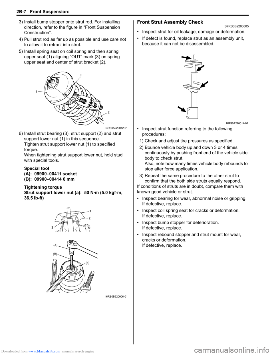
5) Install spring seat on coil spring and then spring upper seat (1) aligning “OUT” mark (3) on spring
upper seat and center of strut bracket (2).
6) Install strut bearing (3), strut support (2) and strut
support lower nut (1) in this sequence.
Tighten strut support lower nut (1) to specified
torque.
When tightening strut support lower nut, hold stud
with special tools.
Special tool
(A): 09900–00411 socket
(B): 09900–00414 6 mm
Tightening torque
Strut support lower nut (a): 50 N·m (5.0 kgf-m,
36.5 lb-ft)Front Strut Assembly CheckS7RS0B2206005
• Inspect strut for oil leakage, damage or deformation.
• If defect is found, replace strut as an assembly unit, because it can not be disassembled.
• Inspect strut function re ferring to the following
procedures:
1) Check and adjust tire pressures as specified.
2) Bounce vehicle body up and down 3 or 4 times continuously by pushing front end of the vehicle side
body to check strut.
Also, note how many times vehicle body rebounds to
stop after force application.
3) Repeat the same procedure to the other strut to confirm that the both side struts equally respond.
If conditions of struts are in doubt, compare them with
known-good vehicle or strut.
• Inspect bearing for wear, abnormal noise or gripping. If defective, replace.
• Inspect coil spring seat for cracks or deformation.
If defective, replace.
• Inspect bump stopper for deterioration. If defective, replace.
• Inspect rebound stopper and strut mount for wear, cracks or deformation.
If defective, replace.
I4RS0A220012-01
I6RS0B220006-01
I4RS0A220014-01