Page 748 of 1496
Downloaded from www.Manualslib.com manuals search engine 5A-104 Automatic Transmission/Transaxle:
4) Apply grease to new differential side oil seal lips.: Grease 99000–25030 (SUZUKI Super Grease C)
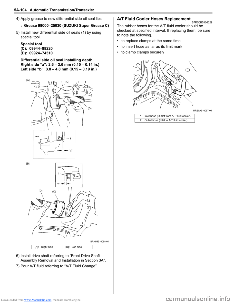
5) Install new differential side oil seals (1) by using special tool.
Special tool
(C): 09944–88220
(D): 09924–74510
Differential side oil seal installing depth
Right side “a”: 2.6 – 3.6 mm (0.10 – 0.14 in.)
Left side “b”: 3.8 – 4.8 mm (0.15 – 0.19 in.)
6) Install drive shaft referring to “Front Drive Shaft Assembly Removal and Installation in Section 3A”.
7) Pour A/T fluid referring to “A/T Fluid Change”.
A/T Fluid Cooler Hoses ReplacementS7RS0B5106029
The rubber hoses for the A/T fluid cooler should be
checked at specified interval. If replacing them, be sure
to note the following.
• to replace clamps at the same time
• to insert hose as far as its limit mark
• to clamp clamps securely
[A]: Right side [B]: Left side
I2RH0B510068-01
1. Inlet hose (Outlet from A/T fluid cooler)
2. Outlet hose (Inlet to A/T fluid cooler)
1 2I4RS0A510057-01
Page 750 of 1496
Downloaded from www.Manualslib.com manuals search engine 5A-106 Automatic Transmission/Transaxle:
Automatic Transaxle Unit Dismounting and
Remounting
S7RS0B5106031
Dismounting1) Take down transaxle with engine. For its procedure, refer to “Engine Assembly Removal and Installation
in Section 1D”.
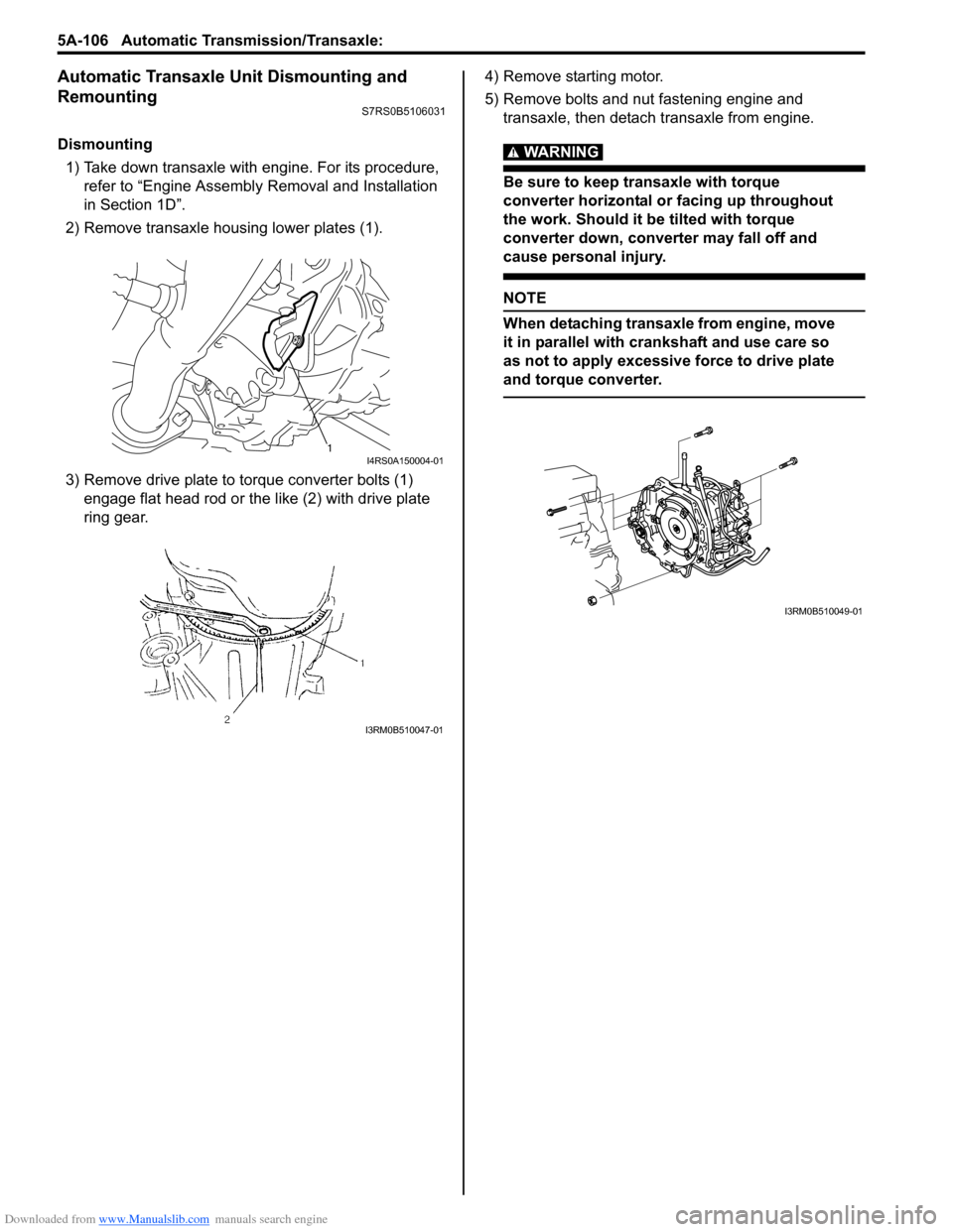
2) Remove transaxle housing lower plates (1).
3) Remove drive plate to torque converter bolts (1) engage flat head rod or the like (2) with drive plate
ring gear. 4) Remove starting motor.
5) Remove bolts and nut fastening engine and
transaxle, then detach transaxle from engine.WARNING!
Be sure to keep transaxle with torque
converter horizontal or facing up throughout
the work. Should it be tilted with torque
converter down, converter may fall off and
cause personal injury.
NOTE
When detaching transaxle from engine, move
it in parallel with cranks haft and use care so
as not to apply excessive force to drive plate
and torque converter.
1I4RS0A150004-01
I3RM0B510047-01
I3RM0B510049-01
Page 751 of 1496
Downloaded from www.Manualslib.com manuals search engine Automatic Transmission/Transaxle: 5A-107
Remounting1) Make sure that torque converter is installed correctly to transaxle.
Refer to “Automatic Transaxle Unit Assembly”.
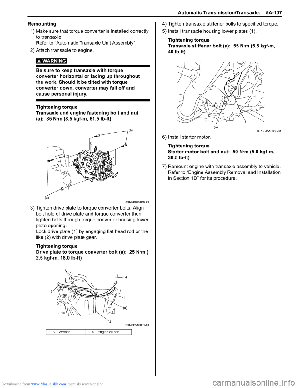
2) Attach transaxle to engine.
WARNING!
Be sure to keep transaxle with torque
converter horizontal or facing up throughout
the work. Should it be tilted with torque
converter down, converter may fall off and
cause personal injury.
Tightening torque
Transaxle and engine fastening bolt and nut
(a): 85 N·m (8.5 kgf-m, 61.5 lb-ft)
3) Tighten drive plate to torque converter bolts. Align bolt hole of drive plate and torque converter then
tighten bolts through torque converter housing lower
plate opening.
Lock drive plate (1) by engaging flat head rod or the
like (2) with drive plate gear.
Tightening torque
Drive plate to torque converter bolt (a): 25 N·m (
2.5 kgf-m, 18.0 lb-ft) 4) Tighten transaxle stiffener bolts to specified torque.
5) Install transaxle housing lower plates (1).
Tightening torque
Transaxle stiffener bolt (a): 55 N·m (5.5 kgf-m,
40 lb-ft)
6) Install starter motor. Tightening torque
Starter motor bolt and nut: 50 N·m (5.0 kgf-m,
36.5 lb-ft)
7) Remount engine with transaxle assembly to vehicle. Refer to “Engine Assembly Removal and Installation
in Section 1D” for its procedure.
3. Wrench 4. Engine oil pan
I3RM0B510050-01
I3RM0B510051-01
1
(a)
I4RS0A510056-01
Page 755 of 1496
Downloaded from www.Manualslib.com manuals search engine Automatic Transmission/Transaxle: 5A-111
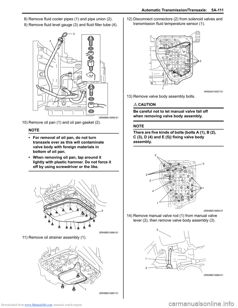
8) Remove fluid cooler pipes (1) and pipe union (2).
9) Remove fluid level gauge (3) and fluid filler tube (4).
10) Remove oil pan (1) and oil pan gasket (2).
NOTE
• For removal of oil pan, do not turn transaxle over as this will contaminate
valve body with foreign materials in
bottom of oil pan.
• When removing oil pan, tap around it lightly with plastic ha mmer. Do not force it
off by using screwdriver or the like.
11) Remove oil strain er assembly (1). 12) Disconnect connectors (2) from solenoid valves and
transmission fluid temperature sensor (1).
13) Remove valve body assembly bolts.
CAUTION!
Be careful not to let manual valve fall off
when removing valve body assembly.
NOTE
There are five kinds of bolts (bolts A (1), B (2),
C (3), D (4) and E (5)) fixing valve body
assembly.
14) Remove manual valve rod (1) from manual valve lever (2), then remove valve body assembly (3).
1 2
4
3
I3RM0B510059-01
I2RH0B510086-01
I2RH0B510087-01
1 2I4RS0A510027-01
I2RH0B510089-01
I2RH0B510090-01
Page 769 of 1496

Downloaded from www.Manualslib.com manuals search engine Automatic Transmission/Transaxle: 5A-125
Direct Clutch Assembly Disassembly and
Reassembly
S7RS0B5106039
Disassembly1) Remove plate snap ring (1) then remove direct clutch retaining plate, discs and separator plates.
2) Using special tool and hydraulic press, remove shaft snap ring (1).
Special tool
(A): 09926–98310
CAUTION!
Do not press direct clutch return spring
subassembly in over 0.7 mm (0.027 in.).
Excessive compression may cause damage
to direct clutch return spring subassembly
and/or piston.
3) Remove direct clutch re turn spring assembly (2).
4) Using a finger to block oil hole (1), apply compressed air (400 – 800 kPa, 4 – 8 kg/cm
2, 57 –
113 psi) to opposite hole, which will assist in removal
of the clutch piston. 5) Remove outer O-ring (1).
6) Remove inner O-ring (2).
7) Remove input shaft seal rings (1).
I2RH0B510162-01
I2RH0B510163-01
I2RH0B510164-01
2. Direct clutch piston
1. Input shaft subassembly
I2RH0B510165-01
I2RH0B510166-01
I2RH0B510167-01
Page 818 of 1496
Downloaded from www.Manualslib.com manuals search engine 5B-4 Manual Transmission/Transaxle:
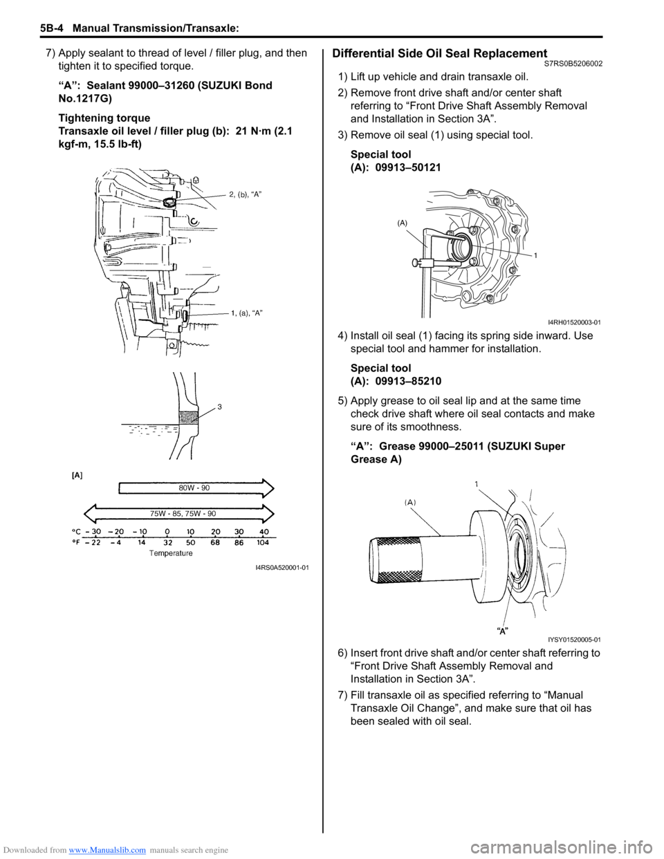
7) Apply sealant to thread of level / filler plug, and then
tighten it to specified torque.
“A”: Sealant 99000–31260 (SUZUKI Bond
No.1217G)
Tightening torque
Transaxle oil level / filler plug (b): 21 N·m (2.1
kgf-m, 15.5 lb-ft)Differential Side Oil Seal ReplacementS7RS0B5206002
1) Lift up vehicle and drain transaxle oil.
2) Remove front drive shaft and/or center shaft referring to “Front Driv e Shaft Assembly Removal
and Installation in Section 3A”.
3) Remove oil seal (1) using special tool.
Special tool
(A): 09913–50121
4) Install oil seal (1) facing its spring side inward. Use special tool and hammer for installation.
Special tool
(A): 09913–85210
5) Apply grease to oil seal lip and at the same time check drive shaft where oil seal contacts and make
sure of its smoothness.
“A”: Grease 99000–25011 (SUZUKI Super
Grease A)
6) Insert front drive shaft and/or center shaft referring to “Front Drive Shaft A ssembly Removal and
Installation in Section 3A”.
7) Fill transaxle oil as specified referring to “Manual Transaxle Oil Change”, and make sure that oil has
been sealed with oil seal.
I4RS0A520001-01
(A)
1
I4RH01520003-01
IYSY01520005-01
Page 820 of 1496
Downloaded from www.Manualslib.com manuals search engine 5B-6 Manual Transmission/Transaxle:
Gear Shift Control Lever and Cable Removal
and Installation
S7RS0B5206004
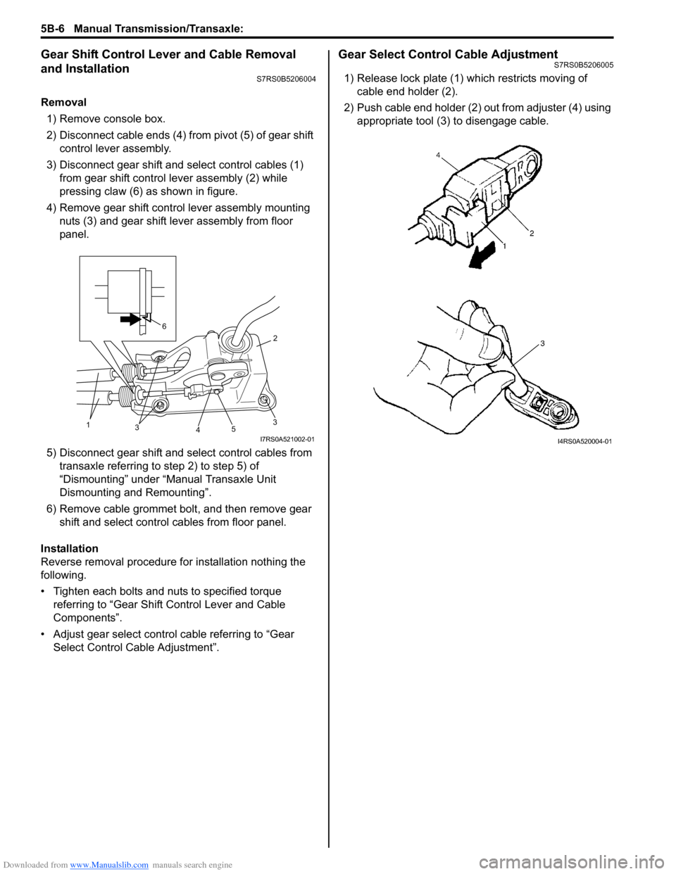
Removal1) Remove console box.
2) Disconnect cable ends (4) from pivot (5) of gear shift control lever assembly.
3) Disconnect gear shift and select control cables (1) from gear shift control lever assembly (2) while
pressing claw (6) as shown in figure.
4) Remove gear shift control lever assembly mounting nuts (3) and gear shift lever assembly from floor
panel.
5) Disconnect gear shift and select control cables from transaxle referring to step 2) to step 5) of
“Dismounting” under “Manual Transaxle Unit
Dismounting and Remounting”.
6) Remove cable grommet bolt, and then remove gear shift and select control cables from floor panel.
Installation
Reverse removal procedure for installation nothing the
following.
• Tighten each bolts and nuts to specified torque referring to “Gear Shift Control Lever and Cable
Components”.
• Adjust gear select control cable referring to “Gear Select Control Cable Adjustment”.
Gear Select Control Cable AdjustmentS7RS0B5206005
1) Release lock plate (1) which restricts moving of cable end holder (2).
2) Push cable end holder (2) out from adjuster (4) using appropriate tool (3) to disengage cable.
35
4
2
31
6
I7RS0A521002-01I4RS0A520004-01
Page 821 of 1496
Downloaded from www.Manualslib.com manuals search engine Manual Transmission/Transaxle: 5B-7
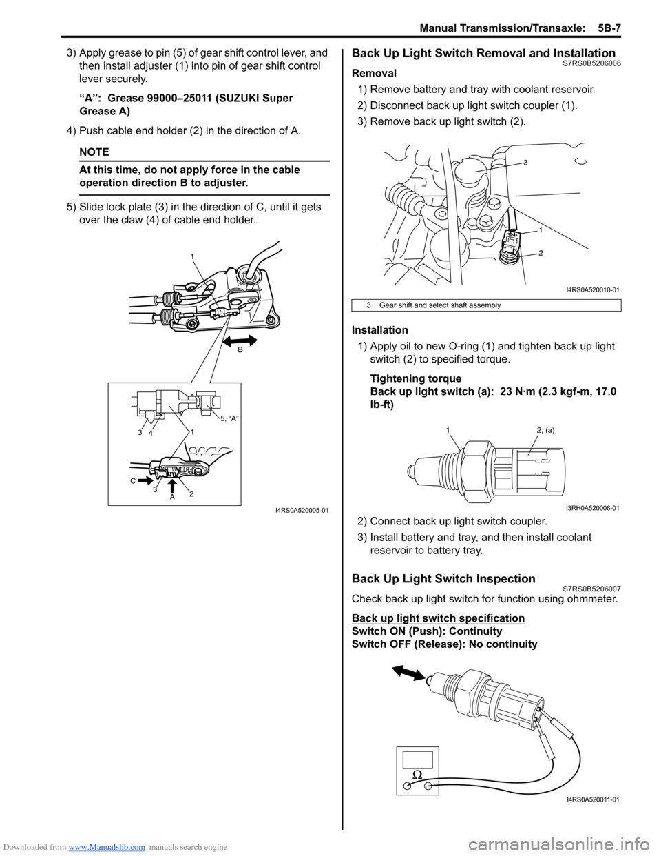
3) Apply grease to pin (5) of gear shift control lever, and then install adjuster (1) into pin of gear shift control
lever securely.
“A”: Grease 99000–25011 (SUZUKI Super
Grease A)
4) Push cable end holder (2) in the direction of A.
NOTE
At this time, do not a pply force in the cable
operation direction B to adjuster.
5) Slide lock plate (3) in the direction of C, until it gets over the claw (4) of cable end holder.
Back Up Light Switch Removal and InstallationS7RS0B5206006
Removal
1) Remove battery and tray with coolant reservoir.
2) Disconnect back up light switch coupler (1).
3) Remove back up light switch (2).
Installation 1) Apply oil to new O-ring (1) and tighten back up light switch (2) to specified torque.
Tightening torque
Back up light switch (a): 23 N·m (2.3 kgf-m, 17.0
lb-ft)
2) Connect back up light switch coupler.
3) Install battery and tray, and then install coolant reservoir to battery tray.
Back Up Light Switch InspectionS7RS0B5206007
Check back up light switch for function using ohmmeter.
Back up light switch specification
Switch ON (Push): Continuity
Switch OFF (Release ): No continuity
3
3
41
2
A
C
1
B
5, “A”
I4RS0A520005-01
3. Gear shift and select shaft assembly
3
1
2
I4RS0A520010-01
1 2, (a)
I3RH0A520006-01
I4RS0A520011-01