2007 SUZUKI GRAND VITARA steering wheel
[x] Cancel search: steering wheelPage 134 of 211

Downloaded from www.Manualslib.com manuals search engine 8-8 VEHICLE LOADING AND TOWING
66J21-03E
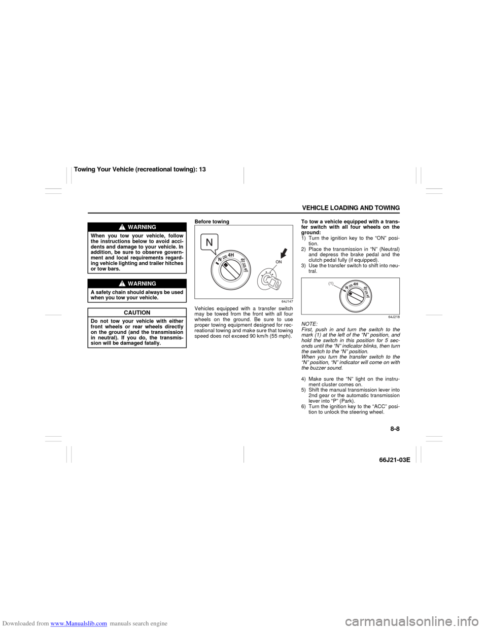
Before towing
64J147
Vehicles equipped with a transfer switch
may be towed from the front with all four
wheels on the ground. Be sure to use
proper towing equipment designed for rec-
reational towing and make sure that towing
speed does not exceed 90 km/h (55 mph).To tow a vehicle equipped with a trans-
fer switch with all four wheels on the
ground:
1) Turn the ignition key to the “ON” posi-
tion.
2) Place the transmission in “N” (Neutral)
and depress the brake pedal and the
clutch pedal fully (if equipped).
3) Use the transfer switch to shift into neu-
tral.
64J218
NOTE:
First, push in and turn the switch to the
mark (1) at the left of the “N” position, and
hold the switch in this position for 5 sec-
onds until the “N” indicator blinks, then turn
the switch to the “N” position.
When you turn the transfer switch to the
“N” position, “N” indicator will come on with
the buzzer sound.
4) Make sure the “N” light on the instru-
ment cluster comes on.
5) Shift the manual transmission lever into
2nd gear or the automatic transmission
lever into “P” (Park).
6) Turn the ignition key to the “ACC” posi-
tion to unlock the steering wheel.
WARNING
When you tow your vehicle, follow
the instructions below to avoid acci-
dents and damage to your vehicle. In
addition, be sure to observe govern-
ment and local requirements regard-
ing vehicle lighting and trailer hitches
or tow bars.
WARNING
A safety chain should always be used
when you tow your vehicle.
CAUTION
Do not tow your vehicle with either
front wheels or rear wheels directly
on the ground (and the transmission
in neutral). If you do, the transmis-
sion will be damaged fatally.
(1)
Towing Your Vehicle (recreational towing): 13
Page 136 of 211

Downloaded from www.Manualslib.com manuals search engine 8-10 VEHICLE LOADING AND TOWING
66J21-03E
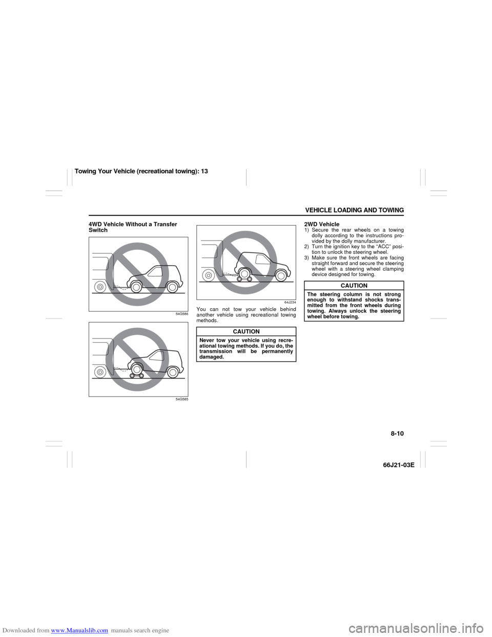
4WD Vehicle Without a Transfer
Switch
54G586
54G58564J234
You can not tow your vehicle behind
another vehicle using recreational towing
methods.
2WD Vehicle1) Secure the rear wheels on a towing
dolly according to the instructions pro-
vided by the dolly manufacturer.
2) Turn the ignition key to the “ACC” posi-
tion to unlock the steering wheel.
3) Make sure the front wheels are facing
straight forward and secure the steering
wheel with a steering wheel clamping
device designed for towing.
CAUTION
Never tow your vehicle using recre-
ational towing methods. If you do, the
transmission will be permanently
damaged.
CAUTION
The steering column is not strong
enough to withstand shocks trans-
mitted from the front wheels during
towing. Always unlock the steering
wheel before towing.
Towing Your Vehicle (recreational towing): 13
Page 138 of 211

Downloaded from www.Manualslib.com manuals search engine INSPECTION AND MAINTENANCE
9
66J21-03E
60G410
INSPECTION AND MAINTENANCEMaintenance Schedule ....................................................... 9-2
Periodic Maintenance Schedule ........................................ 9-3
Drive Belt ............................................................................. 9-7
Engine Oil and Filter ........................................................... 9-7
Gear Oil ................................................................................ 9-11
Automatic Transmission Fluid ........................................... 9-13
Engine Coolant .................................................................... 9-15
Windshield Washer Fluid ................................................... 9-17
Air Cleaner ........................................................................... 9-18
Spark Plugs ......................................................................... 9-18
Brakes .................................................................................. 9-19
Steering Wheel .................................................................... 9-21
Clutch Pedal ........................................................................ 9-22
Tires ...................................................................................... 9-22
Battery .................................................................................. 9-33
Fuses .................................................................................... 9-33
Headlight Aiming ................................................................. 9-36
Bulb Replacement ............................................................... 9-37
Wiper Blades ....................................................................... 9-42
Air Conditioning System .................................................... 9-45
Page 143 of 211

Downloaded from www.Manualslib.com manuals search engine 9-5 INSPECTION AND MAINTENANCE
66J21-03E
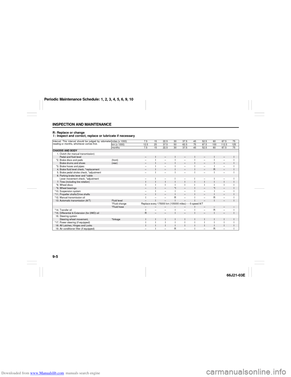
R: Replace or change
I : Inspect and correct, replace or lubricate if necessaryInterval: This interval should be judged by odometer
reading or months, whichever comes first.miles (x 1000) 7.5 15 22.5 30 37.5 45 52.5 60 67.5 75
km (x 1000) 12.52537.55062.57587.5100112.5125
months 7.5 1522.53037.54552.56067.575CHASSIS AND BODY
1. Clutch (for manual transmission)
Pedal and fluid level
–
I
–
I
–
I
–
I
–
I
*2. Brake discs and pads (front) – I – I – I – I – I
Brake drums and shoes
(rear)
–
I
–
I
–
I
–
I
–
I
*3. Brake hoses and pipes – I – I – I – I – I
4.Brake fluid level check, *replacement
–
I
–
I
–
I
–
R
–
I
5. Brake pedal stroke check, *adjustment – I – I – I – I – I
6.Parking brake lever and *cableLever movement check, *adjustment –I–I–I–I–I7.Tires (including tire rotation)
I
I
I
I
I
I
I
I
I
I
*8.Wheel discs IIIIIIIIII
*9.
Wheel bearings
–
I
–
*I
–
I
–
*I
–
I
*10. Suspension system – I – I – I – I – I
*11.
Propeller shafts/Drive shafts
–
I
–
I
–
I
–
I
–
I
*12. Manual transmission oil I – – R – I – R – I
13.
Automatic transmission (A/T)
Fluid level
–
I
–
I
–
I
–
I
–
I
*Fluid change Replace every 175000 km (105000 miles)-----5-speed A/T
*Fluid hose
–
–
–
–
–
I
–
–
–
–
*14. Transfer oil I – – I – I – R – I
*15.
Differential & Extension (for 2WD) oil
R
–
–
I
–
I
–
I
–
I
16. Steering system
Steering wheel movement,
*linkage
I
I
I
I
I
I
I
I
I
I
*17. Power steering (if equipped) I I I I I I I I I I
18.
All Latches, Hinges and Locks
I
I
I
I
I
I
I
I
I
I
19. Air conditioner filter (if equipped) – I – R – I – R – I
Periodic Maintenance Schedule: 1, 2, 3, 4, 5, 6, 9, 10
Page 144 of 211

Downloaded from www.Manualslib.com manuals search engine 9-6 INSPECTION AND MAINTENANCE
66J21-03E
R: Replace or change
I : Inspect and correct, replace or lubricate if necessary
NOTE:
This table shows the service schedule up to 250000 km (150000 miles).
Beyond 250000 km (150000 miles), perform the same services at the same intervals shown in the chart.
Beyond 250000 km (150000 miles), the maintenance services enclosed with a rectangle are required.
Item 9 *I - inspect for wear.Interval: This interval should be judged by odometer
reading or months, whichever comes first.miles (x 1000) 82.5 90 97.5 105112.5 120 127.5 135 142.5 150
km (x 1000) 137.5 150 162.5 175 187.5 200 212.5 225 237.5 250
months 82.5 90 97.5 105 112.5 120 127.5 135 142.5 150CHASSIS AND BODY
1. Clutch (for manual transmission)
Pedal and fluid level
–
I
–
I
–
I
–
I
–
I
*2. Brake discs and pads (front) – I – I – I – I – I
Brake drums and shoes
(rear)
–
I
–
I
–
I
–
I
–
I
*3. Brake hoses and pipes – I – I – I – I – I
4.Brake fluid level check, *replacement
–
I
–
I
–
R
–
I
–
I
5. Brake pedal stroke check, *adjustment – I – I – I – I – I
6.Parking brake lever and *cableLever movement check, *adjustment –I–I–I–I–I7.Tires (including tire rotation)
I
I
I
I
I
I
I
I
I
I
*8.Wheel discs IIIIIIIIII
*9.
Wheel bearings
–
*I
–
I
–
*I
–
I
–
I
*10. Suspension system – I – I – I – I – I
*11.
Propeller shafts/Drive shafts
–
I
–
I
–
I
–
I
–
I
*12. Manual transmission oil – R – I – R – I – R
13.
Automatic transmission (A/T)
Fluid level
–
I
–
I
–
I
–
I
–
I
*Fluid change Replace every 175000 km (105000 miles)-----5-speed A/T
*Fluid hose
–
I
–
–
–
–
–
I
–
–
*14. Transfer oil – I – I – R – I – I
*15.
Differential & Extension (for 2WD) oil
–
I
–
I
–
I
–
I
–
I
16. Steering system
Steering wheel movement,
*linkage
I
I
I
I
I
I
I
I
I
I
*17. Power steering (if equipped) I I I I I I I I I I
18.
All Latches, Hinges and Locks
I
I
I
I
I
I
I
I
I
I
19. Air conditioner filter (if equipped) – R – I – R – I – R
Periodic Maintenance Schedule: 1, 2, 3, 4, 5, 6, 9, 10
Page 160 of 211

Downloaded from www.Manualslib.com manuals search engine 9-22 INSPECTION AND MAINTENANCE
66J21-03E
NOTE:
With disc brakes, the fluid level can be
expected to gradually fall as the brake
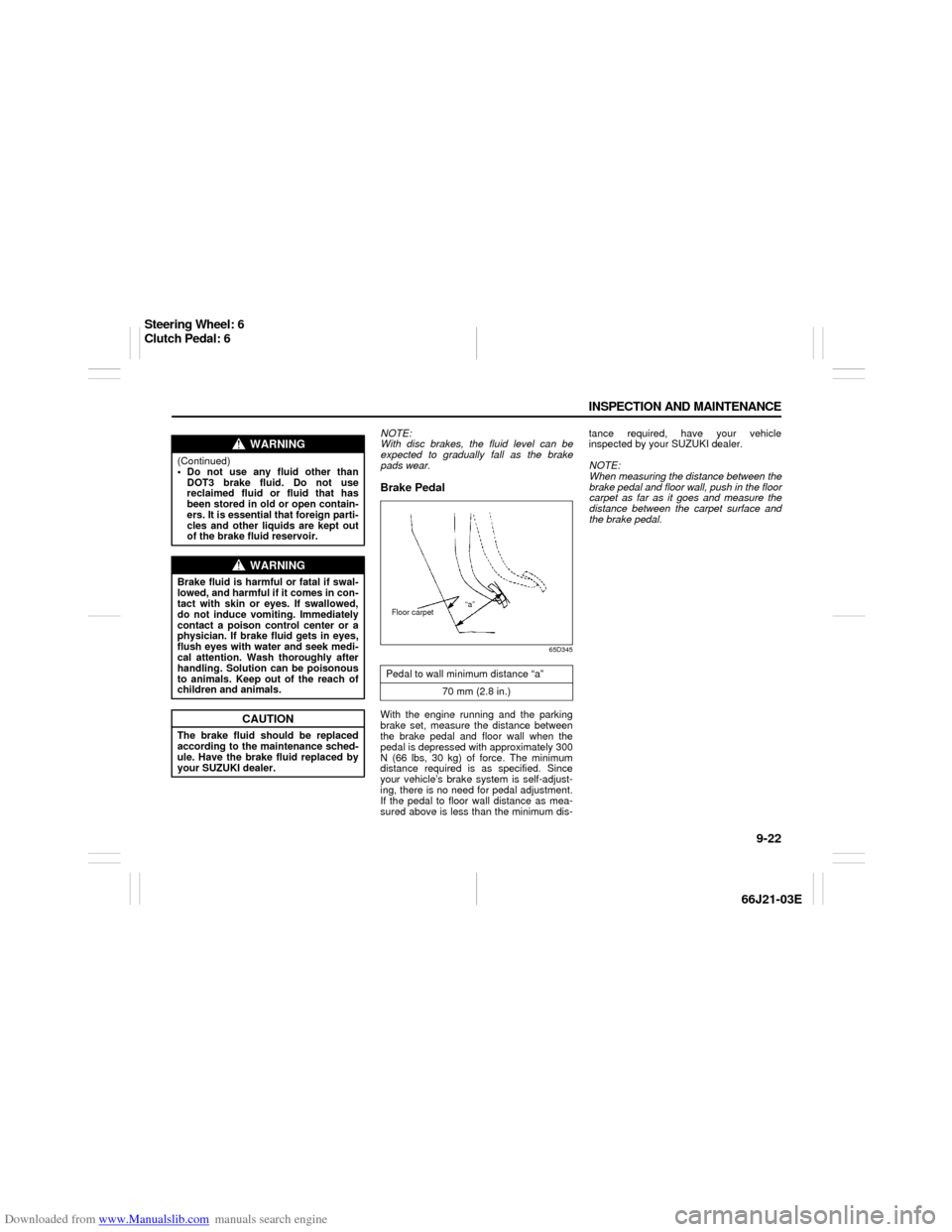
pads wear.Brake Pedal
65D345
With the engine running and the parking
brake set, measure the distance between
the brake pedal and floor wall when the
pedal is depressed with approximately 300
N (66 lbs, 30 kg) of force. The minimum
distance required is as specified. Since
your vehicle’s brake system is self-adjust-
ing, there is no need for pedal adjustment.
If the pedal to floor wall distance as mea-
sured above is less than the minimum dis-tance required, have your vehicle
inspected by your SUZUKI dealer.
NOTE:
When measuring the distance between the
brake pedal and floor wall, push in the floor
carpet as far as it goes and measure the
distance between the carpet surface and
the brake pedal.
WARNING
(Continued)
Do not use any fluid other than
DOT3 brake fluid. Do not use
reclaimed fluid or fluid that has
been stored in old or open contain-
ers. It is essential that foreign parti-
cles and other liquids are kept out
of the brake fluid reservoir.
WARNING
Brake fluid is harmful or fatal if swal-
lowed, and harmful if it comes in con-
tact with skin or eyes. If swallowed,
do not induce vomiting. Immediately
contact a poison control center or a
physician. If brake fluid gets in eyes,
flush eyes with water and seek medi-
cal attention. Wash thoroughly after
handling. Solution can be poisonous
to animals. Keep out of the reach of
children and animals.
CAUTION
The brake fluid should be replaced
according to the maintenance sched-
ule. Have the brake fluid replaced by
your SUZUKI dealer.
Pedal to wall minimum distance “a”
70 mm (2.8 in.)
“a”
Floor carpet
Steering Wheel: 6
Clutch Pedal: 6
Page 161 of 211

Downloaded from www.Manualslib.com manuals search engine 9-23 INSPECTION AND MAINTENANCE
66J21-03E
60G104
Parking Brake Lever
60A226
Check the parking brake for proper adjust-
ment by counting the number of clicks
made by the ratchet teeth as you slowly
pull up on the parking brake lever to the
point of full engagement. The parking
brake lever should stop between the speci-
fied ratchet teeth and the rear wheels
should be securely locked. If the parking
brake is not properly adjusted or the
brakes drag after the lever has been fully
released, have the parking brake inspected
and/or adjusted by your SUZUKI dealer.
Steering Wheel
54G110
Check the play of the steering wheel by
gently turning it from left to right and mea-
suring the distance that it moves before
you feel slight resistance. The play should
be between the specified values. Check
that the steering wheel turns easily and
smoothly without rattling by turning it all the
way to the right and to the left while driving
very slowly in an open area. If the amount
of free play is outside the specification or
you find anything else to be wrong, an
inspection must be performed by your
SUZUKI dealer.
WARNING
If you experience any of the following
problems with your vehicle’s brake
system, have the vehicle inspected
immediately by your SUZUKI dealer.
Poor braking performance
Uneven braking (Brakes not work-
ing uniformly on all wheels.)
Excessive pedal travel
Brake dragging
Excessive noise
(Except ABS equipped vehicle)
Pedal pulsation (Pedal pulsates
when pressed for braking.)
Ratchet tooth specification “b”
5th – 7th
200 N (44 lbs, 20 kg)
“b”
EXAMPLE
Steering wheel play “c”
0 – 30 mm (0.0 – 1.2 in.)EXAMPLE
Tires: 6
Page 164 of 211

Downloaded from www.Manualslib.com manuals search engine 9-26 INSPECTION AND MAINTENANCE
66J21-03E
D. Construction Code
This letter code is used to indicate the
type of ply construction in the tire. The
letter “R” means radial ply tire con-
struction, the letter “D” means diago-
nal or bias ply construction, and the
letter “B” means belted-bias ply con-
struction.
E. Rim Diameter
This two-digit number is the wheel or
rim diameter in inches.
Tire Inflation PressureTire inflation pressure should be checked
when the tire is cold. “Cold tire inflation
pressure” is the pressure in a tire that has
been driven less than 1 mile (1.6 km) or
has been standing for three hours or more.
54G307
The front, rear and spare tire pressure
specifications for your vehicle are shown
below and are listed on the Tire and Load-
ing Information Label, which is located on
the driver’s door lock pillar. The Tire and
Loading Information Label contains the fol-
lowing information:
Seating Capacity
Maximum Allowed Combined Weight of
Occupants and Cargo
Original Tire Size
Recommended Cold Tire Inflation Pres-
sure of Original TiresMeasuring air pressure
Use the following steps to achieve proper
tire inflation:
1) Identify the recommended tire pressure
on the vehicle’s Tire and Loading Infor-
mation Label or in the owner’s manual.
2) Remove the valve cap from the tire
valve stem.
3) Using a reliable pressure gauge, mea-
sure the tire inflation pressure by press-
ing the tire gauge firmly onto the valve
to get a pressure measurement.
Remember that inflation pressures
should be checked when the tires are
“cold”, meaning before they have been
driven one mile or after sitting for three
hours or more allowing the tire to cool
to ambient air temperature.
4) If the air pressure is too high, slowly
release the air by pressing on the tire
valve stem with the edge of the tire
gauge until you reach the correct pres-
sure.
WARNING
Your SUZUKI is equipped with tires
which are all the same type and size.
This is important to ensure proper
steering and handling of the vehicle.
Never mix tires of different size or
type on the four wheels of your vehi-
cle. Mixing tires could cause you to
lose control while driving which may
lead to an accident. The size and type
of tires used should be only those
approved by SUZUKI Motor Corpora-
tion as standard or optional equip-
ment for your vehicle.
Recommended Cold Tire Inflation
Pressures
Front Tires220 kPa
32 psi
Rear Tires220 kPa
32 psi
Spare220 kPa
32 psi
Tires: 6