2007 SUZUKI FORENZA capacities
[x] Cancel search: capacitiesPage 101 of 225

3-25 INSTRUMENT PANEL
85Z03-03E
See “Fog Lamps” under Exterior Lamps in
this section for more information.Cruise Control LightIf your vehicle has this feature, this light will
come on briefly when the ignition is turned
on.
The CRUISE light comes on whenever the
cruise control is set. See “Cruise Control”
in this section. The light will turn off when
the cruise control is turned off.High beam On LightThis light comes on whenever the high-
beam headlamps are on.
See “Headlamp High/Low-Beam Changer”
under “Turn Signal/Multifunction Lever” in
this section for additional information.
Fuel GaugeYour fuel gauge tells you approximately
how much fuel you have left, when the igni-
tion is on. When the indicator nears empty,
the low fuel warning light will come on. You
still have a little fuel left, but you should get
more soon. See “Low Fuel Warning Light”
in this section for more information.
Here are four things that some owners ask
about. None of these show a problem with
your fuel gauge:
At the service station, the gas pump
shuts off before the gauge reads full.
It takes a little more or less fuel to fill up
than the gauge indicated. For example,
the gauge may have indicated the tank
was half full, but it actually took a little
more or less than half the tank’s capacity
to fill the tank. The indicator moves a little when you
turn a corner or speed up.
The gauge goes back to empty when
you turn off the ignition.
For your fuel tank capacity, see “Capacities
and Specifications” in section 5.
Low Fuel Warning LightThis light will come on when the fuel tank is
low on fuel.
To turn it off, add fuel to the fuel tank. See
“Filling Your Tank” in section 5.
N5U3004A
Warning Lights, Gauges and Indicators:
Page 141 of 225
4-17 DRIVING YOUR VEHICLE
85Z03-03E
and shift to NEUTRAL (N). See “Shift-
ing Out of Park (P)” in Section 2.
5) Clamp the steering wheel in a straight-
ahead position with a clamping device
designed for towing.
6) Release the parking brake.
Loading Your VehicleIt is very important to know how much
weight your vehicle can carry. The load
capacities of your vehicle are indicated by
the Gross Vehicle Weight Rating (GVWR),
the Gross Axle Weight Rating (GAWR,
front and rear), the total load capacity, the
seating capacity, and the cargo load
capacity. The GVWR and GAWR (front and
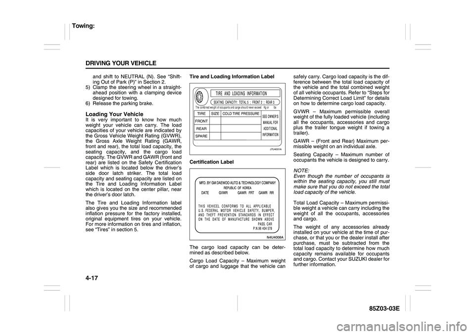
rear) are listed on the Safety Certification
Label which is located below the driver’s
side door latch striker. The total load
capacity and seating capacity are listed on
the Tire and Loading Information Label
which is located on the center pillar, near
the driver’s door latch.
The Tire and Loading Information label
also gives you the size and recommended
inflation pressure for the factory installed,
original equipment tires on your vehicle.
For more information on tires and inflation,
see “Tires” in section 5.Tire and Loading Information Label
Certification Label
The cargo load capacity can be deter-
mined as described below.
Cargo Load Capacity – Maximum weight
of cargo and luggage that the vehicle cansafely carry. Cargo load capacity is the dif-
ference between the total load capacity of
the vehicle and the total combined weight
of all vehicle occupants. Refer to “Steps for
Determining Correct Load Limit” for details
on how to determine cargo load capacity.
GVWR – Maximum permissible overall
weight of the fully loaded vehicle (including
all the occupants, accessories and cargo
plus the trailer tongue weight if towing a
trailer).
GAWR – (Front and Rear) Maximum per-
missible weight on an individual axle.
Seating Capacity – Maximum number of
occupants the vehicle is designed to carry.
NOTE:
Even though the number of occupants is
within the seating capacity, you still must
make sure that you do not exceed the total
load capacity of the vehicle.
Total Load Capacity – Maximum permissi-
ble weight a vehicle can carry including the
weight of all the occupants, accessories
and cargo.
The weight of any accessories already
installed on your vehicle at the time of pur-
chase, or that you or the dealer install after
purchase, must be subtracted from the
total load capacity to determine how much
capacity remains available for occupants
and cargo. Contact your SUZUKI dealer for
further information.
J7U4001A
TIRE
SIZE
COLD TIRE PRESSURE
FRONT
REAR
SPAREThe combined weight of occupants and carge should never exceedKg or lbs
Towing:
Page 144 of 225

SERVICE AND APPEARANCE CARE
5
85Z03-03E
SERVICE AND APPEARANCE CAREService ................................................................................. 5-1
Fuel ....................................................................................... 5-1
Checking Things Under the Hood ..................................... 5-4
Headlamp Aiming ................................................................ 5-23
Bulb Replacement ............................................................... 5-23
Windshield Wiper Blade Replacement .............................. 5-28
Tires ...................................................................................... 5-28
Tire Pressure Monitoring System ...................................... 5-33
Appearance Care ................................................................. 5-45
Vehicle Identification .......................................................... 5-49
Electrical System ................................................................ 5-49
Capacities and Specifications ........................................... 5-54
Page 158 of 225

5-14 SERVICE AND APPEARANCE CARE
85Z03-03E
When replacing the pressure cap, make
sure it is hand-tight.Coolant Surge Tank Pressure Cap
Engine OverheatingYou will find a coolant temperature gauge
on your vehicle’s instrument panel. See
“Engine Coolant Temperature Gauge” in
section 3.If Steam Is Coming From Your Engine
If No Steam Is Coming From Your
Engine
If you get an engine overheat warning, but
see or hear no steam, the problem may not
be too serious. Sometimes the engine can
get a little too hot when you:
Climb a long hill on a hot day.
Stop after high-speed driving.
Idle for long periods in traffic.
If you get the overheat warning with no
sign of steam, try this for a minute or so:
1) In heavy traffic, let the engine idle in
NEUTRAL while stopped. If it is safe to
do so, pull off the road, shift to PARK
(P) or NEUTRAL and let the engine
idle.
2) Turn on your heater to full hot at the
highest fan speed and open the window
as necessary.
If you no longer have the overheat warn-
ing, you can drive. Just to be safe, drive
slower for about 10 minutes. If the warning
doesn’t come back on, you can drive nor-
mally.
CAUTION
Your coolant surge tank cap is a
pressure-type cap and must be
tightly installed to prevent coolant
loss and possible engine damage
from overheating. See “Capacities
and Specifications” for more informa-
tion.
WARNING
Steam from an overheated engine
can burn you badly, even if you just
open the hood. Stay away from the
engine if you see or hear steam com-
ing from it. Just turn it off and get
everyone away from the vehicle until
it cools down. Wait until there is no
sign of steam or coolant before you
open the hood.
If you keep driving when your engine
is overheated, the liquids in it can
catch fire. You or others could be
badly burned. Stop your engine if it
overheats, and get out of the vehicle
until the engine is cool.
CAUTION
If your engine catches fire because
you keep driving with no coolant,
your vehicle can be badly damaged.
The costly repairs would not be cov-
ered by your warranty.
Checking Things Under the Hood:
Page 176 of 225
5-32 SERVICE AND APPEARANCE CARE
85Z03-03E
mounted on a vehicle. The side of the tire
that contains a whitewall, bears white let-
tering or bears manufacturer, brand and or
model name molding that is higher or
deeper than the same moldings on the
other sidewall of the tire.
Passenger (P-Metric) Tire:
A tire used on passenger cars and some
light duty trucks and multipurpose vehicles.
Production Options Weight:
The combined weight of those installed
regular production options weighing over
2.3 kilograms in excess of those standard
items which they replace, not previously
considered in curb weight or accessory
weight, including heavy duty brakes, ride
levelers, roof rack, heavy duty battery, and
special trim.
Recommended Inflation Pressure:
Vehicle manufacturer’s recommended tire
inflation pressure shown on the tire plac-
ard.
Radial Ply Tire:
A pneumatic tire in which the ply cords that
extend to the beads are laid at 90 degrees
to the centerline of the tread.
Rim:
A metal support for a tire and upon which
the tire beads are seated.
Sidewall:
The portion of a tire between the tread and
the bead.Speed Rating:
An alphanumeric code assigned to a tire
indicating the maximum speed at which a
tire can operate.
Traction:
The friction between the tire and the road
surface. The amount of grip provided.
Tread:
The portion of a tire that comes into con-
tact with the road.
Tread wear Indicators:
Narrow bands, sometimes called “wear
bars,” that show across the tread of a tire
when only 2/32 inch of tread remains.
UTQGS:
Uniform Tire Quality Grading Standards, a
tire information system that provides con-
sumers with ratings for a tire’s traction,
temperature and tread wear. Ratings are
determined by tire manufacturers using
government testing procedures. The rat-
ings are molded into the sidewall of the
tire.
Vehicle Capacity Weight:
The number of designated seating posi-
tions multiplied by 150 lbs (68 kg) plus the
rated cargo load.
Vehicle Maximum Load on the Tire:
The load on an individual tire that is deter-
mined by distributing to each axle its share
of the maximum loaded vehicle weight and
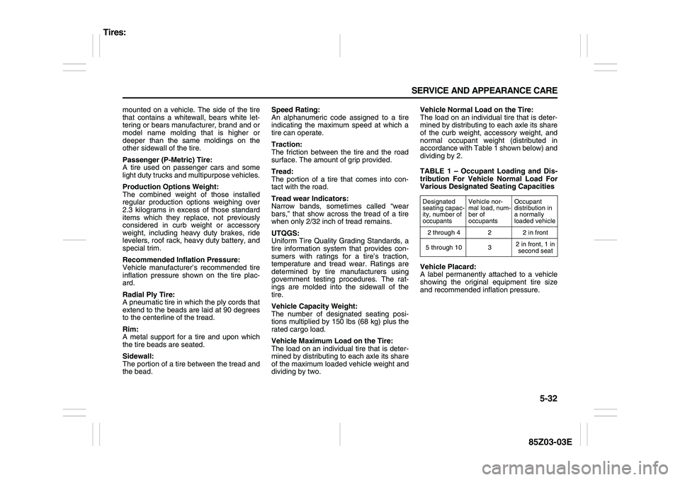
dividing by two.Vehicle Normal Load on the Tire:
The load on an individual tire that is deter-
mined by distributing to each axle its share
of the curb weight, accessory weight, and
normal occupant weight (distributed in
accordance with Table 1 shown below) and
dividing by 2.
TABLE 1 – Occupant Loading and Dis-
tribution For Vehicle Normal Load For
Various Designated Seating Capacities
Vehicle Placard:
A label permanently attached to a vehicle
showing the original equipment tire size
and recommended inflation pressure.
Designated
seating capac-
ity, number of
occupantsVehicle nor-
mal load, num-
ber of
occupantsOccupant
distribution in
a normally
loaded vehicle
2 through 4 2 2 in front
5 through 10 32 in front, 1 in
second seat
Tires:
Page 180 of 225

5-36 SERVICE AND APPEARANCE CARE
85Z03-03E
When rotating your tires, always use the
correct rotation pattern shown here.
Don’t include the compact spare tire in
your tire rotation.
After the tires have been rotated, adjust
the front and rear inflation pressures as
shown on the Tire and Loading Information
label. Make certain that all wheel nuts are
properly tightened. See “Wheel Nut
Torque” under “Capacities and Specifica-
tions” in this section.
Vehicle LoadingThe tires on your vehicle, when they are
inflated to the recommended tire inflation
pressure, have a load-carrying capacity
that is greater than the load that will be on
the tires when the vehicle is at its GVWR
or GAWR limit. Never use replacement
tires that have a load-carrying capacity
less than the original tires on your vehicle.
Tire load-carrying capacity information is
molded into the tire sidewall typically
shown as “Max. Load”. Use of replacement
tires with a lower load-carrying capacity
than the original tires, or failure to keep the
tires inflated to the recommended tire pres-
sure, may reduce the GVWR or GAWR
limit of your vehicle.NOTE:
Use of replacement tires with a higher
load-carrying capacity than the original
tires, or using a tire inflation pressure
higher than the recommended tire inflation
pressure, will not increase the GVWR or
GAWR limit of your vehicle.
When It Is Time for New TiresOne way to tell when it’s time for new tires
is to check the tread wear indicators, which
will appear when your tires have only 1/16
inch (1.6 mm) or less of tread remaining.
You need a new tire if any of the following
statements are true:
You can see the indicators at three or
more places around the tire.
You can see cord or fabric showing
through the tire’s rubber.
WARNING
Rust or dirt on a wheel, or on the
parts to which it is fastened, can
make wheel nuts become loose after
a time. The wheel could come off and
cause an accident. When you change
a wheel, remove any rust or dirt from
places where the wheel attaches to
the vehicle. In an emergency, you can
use a cloth or a paper towel to do
this, but be sure to use a scraper or
wire brush later, if you need to, to get
all the rust or dirt off. See “Changing
a Flat Tire” in this section.
Tires:
Page 187 of 225

5-43 SERVICE AND APPEARANCE CARE
85Z03-03E
Don’t try to put a wheel cover on your com-
pact spare tire. It won’t fit. Store the wheel
cover in the trunk until you have the flat tire
repaired or replaced.Storing the Flat Tire and Tools
Store the flat tire in the compact spare tire
compartment. Place the tire in the com-
partment, then secure the retainer. Store
the jack in its housing in the cargo area.
Secure the jack by turning the retainer
clockwise. Store the tools securely in the
foam tray and place the tray on top of the
tire. Replace the trim cover.
Storing the Spare Tire and Tools
The compact spare tire is for temporary
use only. Replace the compact spare tire
with a full-size tire as soon as you can. See
“Compact Spare Tire” in this section.
WARNING
Incorrect wheel nuts or improperly
tightened wheel nuts can cause the
wheel to come loose and even come
off. This could lead to an accident. Be
sure to use the correct wheel nuts. If
you have to replace them, be sure to
get new SUZUKI original equipment
wheel nuts. Stop somewhere as soon
as you can and have the nuts tight-
ened with a torque wrench to the
proper torque specification. See
“Capacities and Specifications” in
the Index for the wheel nut torque
specification.
CAUTION
Improperly tightened wheel nuts can
lead to brake pulsation and rotor
damage. To avoid expensive brake
repairs, evenly tighten the wheel nuts
in the proper sequence and to the
proper torque specification. See
“Capacities and Specifications” in
the index for the wheel nut torque
specification.
CAUTION
If you install a full-size tire rather than
your compact spare tire, reinstall the
wheel cover as follows:
1) Put the wheel cover on the full-
size tire.
2) Fasten the 4 plastic caps snugly
by hand.
3) Tighten the caps by turning them
an additional 90° with the wheel
wrench.
– The proper tightening torque is a
maximum of 5.9 lb-ft (8 N·m).
– Tightening to the improper
torque can cause damage to the
plastic caps.
CAUTION
Wheel covers will not fit on your com-
pact spare. If you try to put a wheel
cover on the compact spare, you
could damage the cover or the spare.
WARNING
Improperly storing a jack, a tire, or
other equipment in the passenger
compartment of the vehicle could
cause injury. In a sudden stop or col-
lision, loose equipment could strike
someone. Store all these items in the
proper place.
WARNING
Storing a jack, a tire, or other equip-
ment in the passenger compartment
of the vehicle could cause injury. In a
sudden stop or collision, loose
equipment could strike someone.
Store all these in the proper place.
Appearance Care:
Page 196 of 225
5-52 SERVICE AND APPEARANCE CARE
85Z03-03EN4U5038B
HEAD LAMPSBATT PWR
30A
ABS
60A
HVAC BLWR
30A
IGN 2
30A
IGN 1
30A
ILLUM
HORN
MAIN
HEAD LAMPS FRT FOG
A/C CMPRSR
FUEL PUMP
PWR WNDW COOL FAN LOW
DEFOG
COOL FAN HIDEFOG
30A
COOL FAN LOW
20A
PWR WNDW
20A COOL FAN HI
30A
25A
I/P FUSE
15A
DR/LCK
15A
ECM
10AFUEL PUMP
15A
MIR HTD
10A
A/C
10A
FRT FOG
15A
HORN
15A
ILLUM LT
10A
HI BEAM
15A
INJ
15A
DRIVER’S
PWR WNDW
20A
ENG SNSR
15A
STOP LAMPS
15A
LOW BEAM LT
10A
LOW BEAM RT
10A
SPARE
10A
ILLUM RT
10A
SPARE
15A
FUSE
PLR
SPARE
25A
Capacities and Specifications: