2007 SUZUKI AERIO ECO mode
[x] Cancel search: ECO modePage 149 of 232

Downloaded from www.Manualslib.com manuals search engine 8-2 VEHICLE LOADING AND TOWING
54G27-03E
Trailer Towing
54G639
Do not use your vehicle to tow a trailer. The
vehicle is not designed or intended for
such use. Towing a trailer can adversely
affect handling, durability and fuel econ-
omy.
Towing Your Vehicle
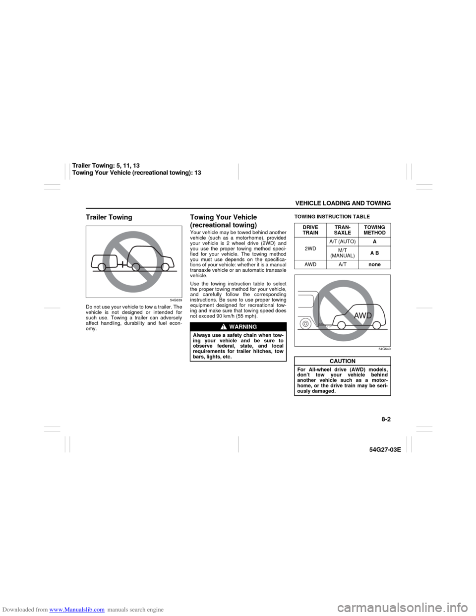
(recreational towing)Your vehicle may be towed behind another
vehicle (such as a motorhome), provided
your vehicle is 2 wheel drive (2WD) and
you use the proper towing method speci-
fied for your vehicle. The towing method
you must use depends on the specifica-
tions of your vehicle: whether it is a manual
transaxle vehicle or an automatic transaxle
vehicle.
Use the towing instruction table to select
the proper towing method for your vehicle,
and carefully follow the corresponding
instructions. Be sure to use proper towing
equipment designed for recreational tow-
ing and make sure that towing speed does
not exceed 90 km/h (55 mph).TOWING INSTRUCTION TABLE
54G640
WARNING
Always use a safety chain when tow-
ing your vehicle and be sure to
observe federal, state, and local
requirements for trailer hitches, tow
bars, lights, etc.
DRIVE
TRAINTRAN-
SAXLETOWING
METHOD
2WDA/T (AUTO)A
M/T
(MANUAL)A B
AWD A/Tnone
CAUTION
For All-wheel drive (AWD) models,
don’t tow your vehicle behind
another vehicle such as a motor-
home, or the drive train may be seri-
ously damaged.
Trailer Towing: 5, 11, 13
Towing Your Vehicle (recreational towing): 13
Page 167 of 232

Downloaded from www.Manualslib.com manuals search engine 9-14 INSPECTION AND MAINTENANCE
54G27-03E
83E010
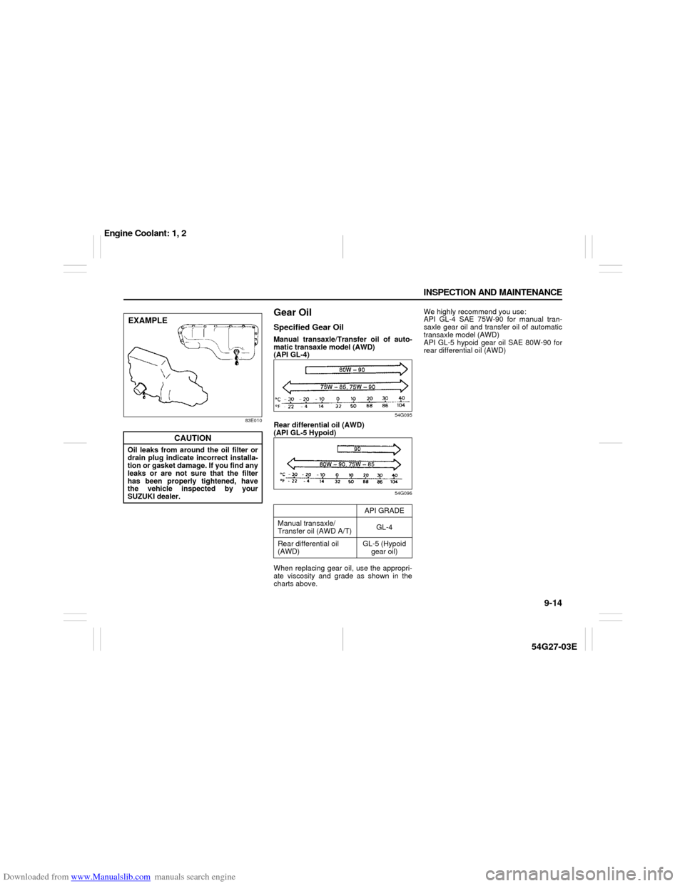
Gear OilSpecified Gear OilManual transaxle/Transfer oil of auto-
matic transaxle model (AWD)
(API GL-4)
54G095
Rear differential oil (AWD)
(API GL-5 Hypoid)
54G096
When replacing gear oil, use the appropri-
ate viscosity and grade as shown in the
charts above.We highly recommend you use:
API GL-4 SAE 75W-90 for manual tran-
saxle gear oil and transfer oil of automatic
transaxle model (AWD)
API GL-5 hypoid gear oil SAE 80W-90 for
rear differential oil (AWD)
CAUTION
Oil leaks from around the oil filter or
drain plug indicate incorrect installa-
tion or gasket damage. If you find any
leaks or are not sure that the filter
has been properly tightened, have
the vehicle inspected by your
SUZUKI dealer.EXAMPLE
API GRADE
Manual transaxle/
Transfer oil (AWD A/T)GL-4
Rear differential oil
(AWD)GL-5 (Hypoid
gear oil)
Engine Coolant: 1, 2
Page 178 of 232

Downloaded from www.Manualslib.com manuals search engine 9-25 INSPECTION AND MAINTENANCE
54G27-03E
Clutch Pedal
60B318
Check the clutch pedal for smooth opera-
tion and clutch fluid level from time to time.
If clutch dragging is felt with the pedal fully
depressed, have the clutch inspected by
your SUZUKI dealer. If the clutch fluid level
is near the “MIN” line, fill it up to the “MAX”
line with DOT3 brake fluid.
TiresFor safe operation of your vehicle, it is
important that the tires be the correct type
and size, in good condition, and properly
inflated. Be sure to follow the requirements
and recommendations in this section.Tire Sidewall LabelingUseful information about a tire is molded
into its sidewall. The example below shows
a typical passenger car tire.
Typical Passenger Car Tire Sidewall
67D027
A. Tire Manufacturer
The name of the tire manufacturer is
shown here.
B. Tire Name/Model
The tire name or model is shown
here.C. Tire Size
The tire size code is a combination of
letters and numbers used to define a
particular tire’s width, height, aspect
ratio, construction type, and service
description. See the “Tire Size” expla-
nation later in this section for more
details.
D. U.S. DOT Tire Identification Number
The Department of Transportation
(DOT) marking indicates that the tire
is in compliance with the U.S. Depart-
ment of Transportation Motor Vehicle
Safety Standards. The letters and
numbers following the DOT marking
is the Tire Identification Number
(TIN). The TIN identifies the tire man-
ufacturer and plant, tire size, and date
the tire was manufactured.
E. Uniform Tire Quality Grading (UTQG)
Tire manufacturers are required to
grade tires based on three perfor-
mance factors: treadwear, traction
and temperature resistance. Refer to
the “Uniform Tire Quality Grading”
section for more details.
F. Load Rating
Load rating is the maximum weight a
tire is designed to support in normal
service.
G. Max Inflation Pressure
Max inflation pressure is the maxi-
mum inflation pressure a tire is
designed for.
H. Tire Ply Material
These tire markings describe the type
AH B
G
E
FD
J I
C
Tires: 6
Page 184 of 232

Downloaded from www.Manualslib.com manuals search engine 9-31 INSPECTION AND MAINTENANCE
54G27-03E
Changing Wheels
54G420
To change a wheel, use the following pro-
cedure:
1) Remove the jack, tools and spare
wheel from the vehicle.
2) Loosen, but do not remove the wheel
nuts.
3) Jack up the vehicle (follow the jacking
instructions in the “EMERGENCY SER-
VICE” section in this manual).
4) Remove the wheel nuts and wheel.
5) Install the new wheel and replace the
wheel nuts with their cone shaped end
facing the wheel. Tighten each nut
snugly by hand until the wheel is
securely seated on the hub.
54G116
6) Lower the jack and fully tighten the nuts
(to the specified torque) in a crisscross
fashion with a wrench as shown in the
illustration.Snow TiresYour vehicle is equipped with all-season
tires which are designed for use in summer
and most winter conditions. For improved
traction in severe winter conditions,
SUZUKI recommends mounting radial
snow tires on all four wheels. Snow tires
must be the same size as the standard
tires. Also be sure to use the tires of the
same type and brand on all four wheels of
your vehicle.
CAUTION
For All-wheel drive (AWD) models,
driving with an underinflated com-
pact spare tire or over 80 km/h (50
mph) while using a compact spare
tire can result in damage to the drive
train.
Wheel tightening torque
85 Nm (61.5 lb-ft, 8.5 kg-m)
Loosen
Tighten
Tires: 6
Battery: 9
Page 185 of 232

Downloaded from www.Manualslib.com manuals search engine 9-32 INSPECTION AND MAINTENANCE
54G27-03E
GLOSSARY OF TIRE TERMINOL-
OGYAccessory Weight – the combined weight
(in excess of those standard items which
may be replaced) of automatic transaxle,
power steering, power brakes, power win-
dows, power seats, radio, and heater, to
the extent that these items are available as
factory-installed equipment (whether
installed or not).
Cold Tire Inflation Pressure – the pressure
in a tire that has been driven less than 1
mile or has been standing for three hours
or more.
Curb Weight – the weight of a motor vehi-
cle with standard equipment including the
maximum capacity of fuel, oil, and coolant,
and, if so equipped, air conditioning and
additional weight optional engine.
Intended Outboard Sidewall – (1) the side-
wall that contains a whitewall, bears white
lettering or bears manufacturer, brand,
and/or model name molding that is higher
or deeper than the same molding on the
other sidewall of the tire, or (2) the outward
facing sidewall of an asymmetrical tire that
has a particular side that must always face
outward when mounted on a vehicle.
Maximum Inflation Pressure – the maxi-
mum cold inflation pressure a tire is
designed to support in normal service.
Maximum Loaded Vehicle Weight – the
sum of curb weight, accessory weight,vehicle capacity weight (total load capac-
ity), and production options weight.
Normal Occupant Weight – 68 kilograms
times the number of occupants specified in
the second column of Table 1 (shown
below).
Occupant distribution – distribution of
occupants in a vehicle as specified in the
third column of Table 1 (shown below).
Production Options Weight – the combined
weight of those installed regular production
options weighing over 2.3 kilograms in
excess of those standard items which they
replace, not previously considered in curb
weight or accessory weight, including
heavy duty brakes, ride levelers, roof rack,
heavy duty battery, and special trim.
Recommended Inflation Pressure – the
cold tire inflation pressure recommended
by a manufacturer.
Rim – metal support for a tire or tire and
tube assembly upon which the tire beads
are seated.
Vehicle Capacity Weight – the rated cargo
and luggage load plus 68 kilograms (150
lbs) times the vehicle’s designated seating
capacity.
Vehicle Maximum Load on the Tire – the
load on an individual tire that is determined
by distributing to each axle its share of the
maximum loaded vehicle weight and divid-
ing by two.Vehicle Normal Load on the Tire – the load
on an individual tire that is determined by
distributing to each axle its share of the
curb weight, accessory weight, and normal
occupant weight (distributed in accordance
with Table 1 shown below) and dividing by
2.
TABLE 1 – Occupant Loading and Dis-
tribution For Vehicle Normal Load For
Various Designated Seating Capacities
Vehicle LoadingYour vehicle was designed for specific
load capacities. The load capacities of
your vehicle are indicated by the Gross
Vehicle Weight Rating (GVWR), the Gross
Axle Weight Rating (GAWR, front and
rear), and the total load capacity, the seat-
ing capacity, and the cargo load capacity.
The GVWR and GAWR (front and rear) are
listed on the Safety Certification Label
which is located below the driver’s side
door latch striker. The total load capacity
and seating capacity are listed on the Tire
and Loading Information Label which is
located below the Safety CertificationDesignated
seating capac-
ity, number of
occupantsVehicle normal
load, number
of occupantsOccupant
distribution in
a normally
loaded vehicle
2 through 4 2 2 in front
5 through 10 32 in front, 1 in
second seat
Fuses: 7
Page 202 of 232

Downloaded from www.Manualslib.com manuals search engine 10-5 EMERGENCY SERVICE
54G27-03E
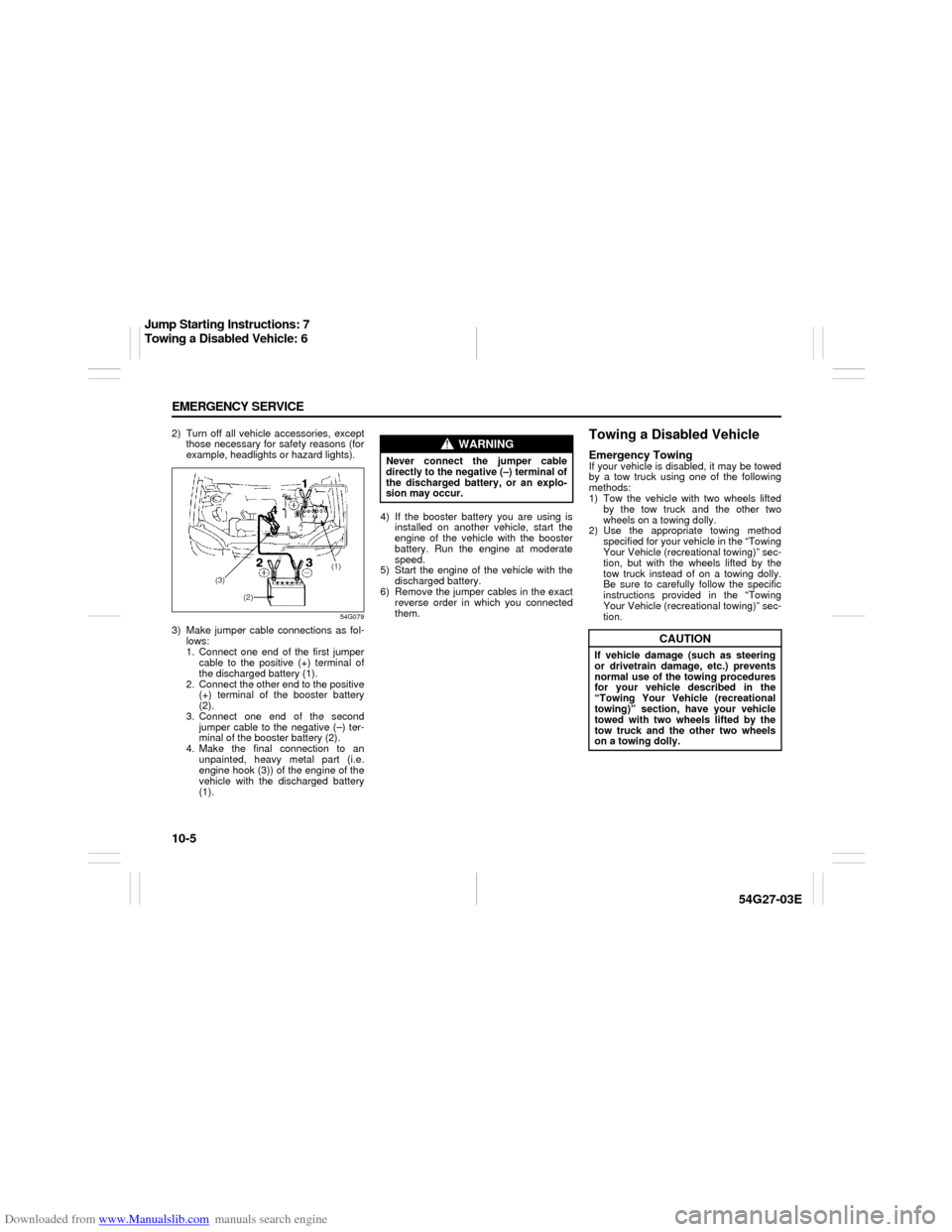
2) Turn off all vehicle accessories, except
those necessary for safety reasons (for
example, headlights or hazard lights).
54G079
3) Make jumper cable connections as fol-
lows:
1. Connect one end of the first jumper
cable to the positive (+) terminal of
the discharged battery (1).
2. Connect the other end to the positive
(+) terminal of the booster battery
(2).
3. Connect one end of the second
jumper cable to the negative (–) ter-
minal of the booster battery (2).
4. Make the final connection to an
unpainted, heavy metal part (i.e.
engine hook (3)) of the engine of the
vehicle with the discharged battery
(1).4) If the booster battery you are using is
installed on another vehicle, start the
engine of the vehicle with the booster
battery. Run the engine at moderate
speed.
5) Start the engine of the vehicle with the
discharged battery.
6) Remove the jumper cables in the exact
reverse order in which you connected
them.
Towing a Disabled VehicleEmergency TowingIf your vehicle is disabled, it may be towed
by a tow truck using one of the following
methods:
1) Tow the vehicle with two wheels lifted
by the tow truck and the other two
wheels on a towing dolly.
2) Use the appropriate towing method
specified for your vehicle in the “Towing
Your Vehicle (recreational towing)” sec-
tion, but with the wheels lifted by the
tow truck instead of on a towing dolly.
Be sure to carefully follow the specific
instructions provided in the “Towing
Your Vehicle (recreational towing)” sec-
tion.
(1)
(3)
(2)
WARNING
Never connect the jumper cable
directly to the negative (–) terminal of
the discharged battery, or an explo-
sion may occur.
CAUTION
If vehicle damage (such as steering
or drivetrain damage, etc.) prevents
normal use of the towing procedures
for your vehicle described in the
“Towing Your Vehicle (recreational
towing)” section, have your vehicle
towed with two wheels lifted by the
tow truck and the other two wheels
on a towing dolly.
Jump Starting Instructions: 7
Towing a Disabled Vehicle: 6