2007 SUBARU OUTBACK Back up lights
[x] Cancel search: Back up lightsPage 41 of 442

1-14Seat, seatbelt and SRS airbags
If the shoulder portion of the belt crosses
the face or neck, adjust the shoulder belt
anchor height (window-side seating posi-
tions only) and then if necessary move the
child closer to the belt buckle to help
provide a good shoulder belt fit. Care must
be taken to securely place the lap belt as
low as possible on the hips and not on thechild ’s waist. If the shoulder portion of the
belt cannot be properly positioned, a child
restraint system should be used. Never
place the shoulder belt under the child ’s
arm or behind the child ’s back.
! Expectant mothers
Expectant mothers also need to use the
seatbelts. They should consult their doctor
for specific recommendations. The lap belt
should be worn securely and as low as possible over the hips, not over the waist.
& Emergency Locking Retrac-
tor (ELR)
The driver ’s seatbelt has an Emergency
Locking Retractor (ELR).
The emergency locking retractor allows
normal body movement but the retractor
locks automatically during a sudden stop,
impact or if you pull the belt very quickly
out of the retractor. & Automatic/Emergency Lock-
ing Retractor (A/ELR)
Each passenger ’s seatbelt has an Auto-
matic/Emergency Locking Retractor (A/
ELR). The Automatic/Emergency Locking
Retractor normally functions as an Emer-
gency Locking Retractor (ELR). The A/
ELR has an additional locking mode“ Automatic Locking Retractor (ALR)
mode ”intended to secure a child restraint
system. When the seatbelt is once drawn
out completely and is then retracted even
slightly, the retractor locks the seatbelt in
that position and the seatbelt cannot be
extended. As the belt is rewinding, clicks
will be heard which indicate the retractor
functions as ALR. When the seatbelt is
retracted fully, ALR mode is released.
When securing a child restraint system on the passengers
’seats, the seatbelt must
be changed over to the Automatic Locking
Retractor (ALR) mode.
When the child restraint system is re-
moved, make sure that the retractor is
restored to the Emergency Locking Re-
tractor (ELR) function by allowing the
seatbelt to retract fully.
For instructions on how to convert the
retractor to the ALR mode and restore it to
the ELR mode, see the “Child restraint
systems ”section in this chapter.
& Seatbelt warning light
and chime
Your vehicle is equipped with a seatbelt
warning device at the driver ’s and front
passenger ’s seat, as required by current
safety standards.
With the ignition switch turned to the “ON ”
position, this device reminds the driver
and front passenger to fasten their seat-
belts by illuminating the warning lights in
the locations indicated in the following
illustration and sounding a chime.
Page 75 of 442

1-48Seat, seatbelt and SRS airbags
. Do not apply any strong impact to the
front passenger ’s seat such as by kicking.
. Do not spill liquid on the front passen-
ger ’s seat. If liquid is spilled, wipe it off
immediately. . Do not remove or disassemble the front
passenger ’s seat.
. Do not install any accessory (such as
an audio amplifier) other than a genuine
SUBARU accessory under the front pas-senger ’s seat.
. Do not place anything (shoes, umbrel-
la, etc.) under the front passenger ’s seat.
. The front passenger ’s seat must not be
used with the head restraint removed. . Do not leave any article including a
child restraint system on the front passen- ger ’s seat or the seatbelt tongue and
buckle engaged when you leave yourvehicle. . Do not place a magnet near the
seatbelt buckle and the seatbelt retractor.. Do not use front seats with their back-
ward-forward position and seatback not
being locked into place securely. If any of
them are not locked securely, adjust them
again. For adjusting procedure, refer tothe “Manual seat ”in the front seats section
in Chapter 1 in this owner ’s manual.
(Models equipped with manual seats only)
If the seatbelt buckle switch and/or front passenger
’s occupant detection system
have failed, the SRS airbag system
warning light will illuminate. Have the
system inspected by your SUBARU deal-
er immediately if the SRS airbag system
warning light comes on.
If your vehicle has sustained impact, this
may affect the proper function of the
Subaru advanced frontal airbag system.
Have your vehicle inspected at your
SUBARU dealer.
NOTE
The front passenger ’s SRS side airbag,
SRS curtain airbag and seatbelt pre-
tensioner are not controlled by the
Subaru advanced frontal airbag sys-tem. !
Passenger ’s frontal airbag ON and
OFF indicators
or: Front passenger ’s frontal airbag
ON indicator
or: Front passenger ’s frontal airbag
OFF indicator
The front passenger ’s frontal airbag ON
and OFF indicators show you the status of
the front passenger ’s SRS frontal airbag.
The indicators are located between the
map lights.
When the ignition switch is turned to the “ ON ”position, both the ON and OFF
indicators illuminate for 6 seconds during
which time the system is checked. Follow-
ing the system check, both indicators
extinguish for 2 seconds. After that, one
of the indicators illuminates depending on
the status of the front passenger ’s SRS
Page 101 of 442

2-10Keys and doors
when the “”button is pressed. This light
stays illuminated for approximately 30
seconds if any of the doors or the rear
gate (Station wagon) is not opened.
If the “
”button is pressed before 30
seconds have elapsed, this light will go
out. The interior light must be set to the
middle position in order for this function
to operate.
A SUBARU dealer can change the illumi-
nation period setting of the interior light in
accordance with your preference. Contact
the nearest SUBARU dealer for details. & Vehicle finder function
Use this function to find your vehicle
parked among many vehicles in a large
parking lot. Provided you are within 30 feet
(10 meters) of the vehicle, pressing the “
”
button three times in a five-second period
will cause your vehicle ’s horn to sound
once and its turn signal lights to flash threetimes.
NOTE
If the interval between presses is too
short when you press the “
”button
three times, the system may not re-
spond to the signals from the remote
transmitter. &
Sounding a panic alarm
A“PANIC ”button is located on the back of
the transmitter.
To activate the alarm, press the “PANIC ”
button once.
The horn will sound and the turn signal
lights will flash.
To deactivate the panic alarm, press any
button on the remote transmitter. Unless a
button on the remote is pressed, the alarm
will be deactivated after approximately 30seconds. & Selecting audible signal op- eration
Using an electronic chirp, the system will
give you an audible signal when the doors
lock and unlock. If desired, you may turn the audible signal off.
Do the following to deactivate the audible
signal. You can also use the same steps
to restore the function.
1. Sit in the driver
’s seat and shut all
doors and the rear gate.
2. Hold down the UNLOCK side of the
power door locking switch.
3. While holding down the “UNLOCK ”
side of the power door locking switch, pull
the key out and re-insert it into the ignition
switch at least 6 times within 10 seconds
after Step 2.
4. Open and close the driver ’s door once
within 10 seconds after Step 3.
5. The turn signal lights flash 3 times to
indicate completion of the setting.
You may have the above settings done by
your SUBARU dealer.
& Replacing the battery
CAUTION
Do not let dust, oil or water get on or
in the transmitter when replacing
the battery.
When the transmitter battery begins to get
weak, transmitter range will begin to
decrease. Replace the battery as soon
Page 108 of 442

.The 30-second standby time can be
eliminated if you prefer. Have it per-
formed by your SUBARU dealer.. If your vehicle is a Sedan and you
unlock the trunk using the remotetransmitter ’s “
”button with the
alarm system armed, the system will
be temporarily placed in a standby
state. The system will go back to the
surveillance state upon locking thetrunk.. The system is in the standby mode
for a 30-second period after locking the
doors with the remote transmitter. The
security indicator light will flash at
short intervals during this period. . If any of the following actions is
done during the standby period, the
system will not switch to the surveil-
lance state.
.Doors are unlocked using the
remote transmitter. . Any door (including the rear gate
of a Station wagon or the trunk of a
Sedan) is opened. . Ignition switch is turned to the
“ ON ”position. &
Disarming the system
Briefly press the “
”button (for less than
two seconds) on the remote transmitter.
The driver ’s door will unlock, an electronic
chirp will sound twice, the turn signal lights
will flash twice and the indicator light will
go off.
To unlock all other doors and the rear gate
(Station wagon), briefly press the “
”
button a second time within 5 seconds. NOTE
If the interval between the first and
second presses of the “
”button (for
unlocking of all of the doors and the
rear gate) is extremely short, the sys-
tem may not respond.
Or the system can be disarmed by the
following method, too. . Insert the key in the door lock of the
driver ’s door and turn it to the unlock
position. ! Emergency disarming
If you cannot disarm the system using the
transmitter (i.e. the transmitter is lost,
broken or the transmitter battery is too
weak), you can disarm the system without
using the transmitter.
The system can be disarmed if you turn
the ignition switch from the “LOCK ”to the “
ON ”position with a registered key.
Insert the key in the door lock of thedriver ’s door and turn it to the unlock
position.
& Valet mode
When you choose the valet mode, the
alarm system does not operate. In valet
mode, the remote transmitter is used only
for locking and unlocking the doors and
rear gate (Station wagon) and panicactivation.
To enter the valet mode, change the
setting of your vehicle ’s alarm system for
deactivation mode. (Refer to “Activating
and deactivating the alarm system ”in this
section.) The security indicator light will
continue to flash once every three sec-
onds indicating that the system is in the
valet mode.
To exit valet mode, change the setting of
your vehicle ’s alarm system for activation
mode. (Refer to “Activating and deactivat-
ing the alarm system ”in this section.)
& Passive arming
When passive arming mode has been
programmed by the dealer, arming of the
system is automatically accomplished
without using the remote transmitter. Note Keys and doors
2-17
– CONTINUED –
Page 154 of 442

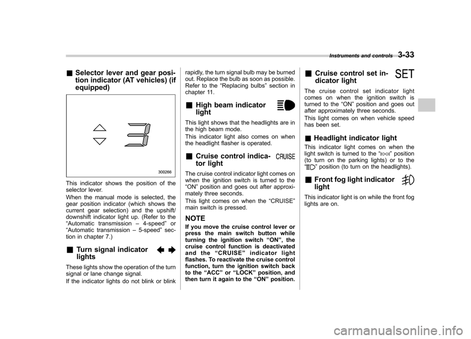
&Selector lever and gear posi-
tion indicator (AT vehicles) (if equipped)
This indicator shows the position of the
selector lever.
When the manual mode is selected, the
gear position indicator (which shows the
current gear selection) and the upshift/
downshift indicator light up. (Refer to the“Automatic transmission –4-speed ”or
“ Automatic transmission –5-speed ”sec-
tion in chapter 7.)
& Turn signal indicator lights
These lights show the operation of the turn
signal or lane change signal.
If the indicator lights do not blink or blink rapidly, the turn signal bulb may be burned
out. Replace the bulb as soon as possible.
Refer to the
“Replacing bulbs ”section in
chapter 11.
& High beam indicator light
This light shows that the headlights are in
the high beam mode.
This indicator light also comes on when
the headlight flasher is operated. &Cruise control indica-
tor light
The cruise control indicator light comes on
when the ignition switch is turned to the“ON ”position and goes out after approxi-
mately three seconds.
This light comes on when the “CRUISE ”
main switch is pressed.
NOTE
If you move the cruise control lever or
press the main switch button while
turning the ignition switch “ON ”, the
cruise control function is deactivated
and the “CRUISE ”indicator light
flashes. To reactivate the cruise control
function, turn the ignition switch back
to the “ACC ”or “LOCK ”position, and
then turn it again to the “ON ”position. &
Cruise control set in-
dicator light
The cruise control set indicator light
comes on when the ignition switch is
turned to the “ON ”position and goes out
after approximately three seconds.
This light comes on when vehicle speed
has been set. & Headlight indicator light
This indicator light comes on when the
light switch is turned to the “
”position
(to turn on the parking lights) or to the “
” position (to turn on the headlights).
& Front fog light indicator light
This indicator light is on while the front fog
lights are on. Instruments and controls
3-33
Page 160 of 442

Light control switch
WARNING
To prevent battery discharge result-
ing from accidentally leaving your
lights on when your vehicle is
parked, the light switch operates
only when the ignition switch is inthe “ON ”position. In any other
position, the vehicle ’s lights will be
out.
If you park your vehicle on a road-
side at night, use the hazard warn-
ing flasher to alert the other drivers.
The light switch operates only when the
ignition switch is in the “ON ”position. &
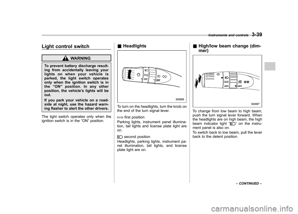
Headlights
To turn on the headlights, turn the knob on
the end of the turn signal lever.
first position
Parking lights, instrument panel illumina-
tion, tail lights and license plate light areon.
second position
Headlights, parking lights, instrument pa-
nel illumination, tail lights, and license
plate light are on. &
High/low beam change (dim- mer)
To change from low beam to high beam,
push the turn signal lever forward. When
the headlights are on high beam, the high
beam indicator light “
”on the instru-
ment panel is also on.
To switch back to low beam, pull the lever
back to the detent position. Instruments and controls
3-39
– CONTINUED –
Page 163 of 442

3-42Instruments and controls
Parking light switch
The parking light switch operates regard-
less of the ignition switch position.
By pushing the front end of this switch,
following lights will come on. –Parking lights
– Front and rear side marker lights
– Tail lights
– License plate lights
To turn off, push the rear end of the
parking light switch.
Avoid leaving these lights on for a long
time because that will run down the
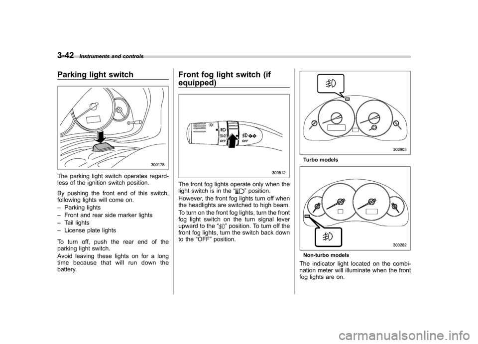
battery. Front fog light switch (if equipped)
The front fog lights operate only when the
light switch is in the
“”position.
However, the front fog lights turn off when
the headlights are switched to high beam.
To turn on the front fog lights, turn the front
fog light switch on the turn signal lever
upward to the “
”position. To turn off the
front fog lights, turn the switch back down
to the “OFF ”position.
Turbo models
Non-turbo models
The indicator light located on the combi-
nation meter will illuminate when the front
fog lights are on.
Page 170 of 442

button, the compass display is toggled on
or off. When the compass is on, an
illuminated compass reading will appear
in the lower part of the mirror.
Even with the mirror in anti-glare mode,
the mirror surface turns bright if the
transmission is shifted into reverse. This
is to ensure good rearward visibility duringreversing. !Photosensors
The mirror has a photosensor attached on
both the front and back sides. If the glare
from the headlights of vehicles behind you
strikes the mirror, these sensors detect it
and make the reflection surface of the
mirror dimmer to help prevent you from
being blinded. For this reason, use care
not to cover the sensors with stickers, or other similar items. Periodically wipe the
sensors clean using a piece of dry soft
cotton cloth or an applicator. !
Compass calibration
1. For optimum calibration, switch off all
nonessential electrical accessories (rear
window defogger, heater/air conditioning
system, spotlight, etc.) and ensure all
doors are shut.
2. Drive to an open, level area away from
large metallic objects or structures and
make certain the ignition switch is in the“ ON ”position.
3. Press and hold the left button for 3
seconds then release, and the compass
will enter the calibration mode. “CAL ”and
direction will be displayed.
4. Drive slowly in a circle until “CAL ”
disappears from the display (approxi-
mately two or three circles). The compass
is now calibrated.
5. Further calibration may be necessary
should outside influences cause the mirror
to read inaccurately. You will know that
this has occurred if your compass begins
to read in only limited directions. Should
you encounter this situation, return to step
one of the above procedure and recali-
brate the mirror. !
Compass zone adjustment
1. The zone setting is factory preset to
Zone 8. Refer to the “Compass calibration
zone ”map attached to the end of this
manual to verify that the compass zone
setting is correct for your geographicallocation.
2. Press and hold the right button for 3
seconds then release, and the word“ ZONE ”will briefly appear and then the
zone number will be displayed.
3. Press the right-hand button repeatedly
to cycle the display through all possible
zone settings. Stop cycling when the
correct zone setting for your location isdisplayed.
4. Releasing the button for 3 seconds will
exit the zone setting mode. Instruments and controls
3-49
– CONTINUED –