2007 SUBARU OUTBACK set clock
[x] Cancel search: set clockPage 123 of 442

Instruments and controlsSelector lever position indicator (AT vehicles)(if equipped) ..................................................... 3-32
Gear position indicator (AT vehicles) (if equipped) ..................................................... 3-32
Selector lever and gear position indicator (AT vehicles) (if equipped) ...................................... 3-33
Turn signal indicator lights ................................. 3-33
High beam indicator light ................................... 3-33
Cruise control indicator light .............................. 3-33
Cruise control set indicator light ......................... 3-33
Headlight indicator light ..................................... 3-33
Front fog light indicator light .............................. 3-33
Clock (Vehicle without Navigation System) ............................................................ 3-34
Information display (Non-turbo models without Navigation System) ........................... 3-34
Outside temperature indicator ............................ 3-35
Current fuel consumption ................................... 3-36
Average fuel consumption .................................. 3-36
Driving range on remaining fuel .......................... 3-37
Journey time ...................................................... 3-38
Light control switch ........................................... 3-39
Headlights. ......................................................... 3-39 High/low beam change (dimmer) ...
..................... 3-39
Headlight flasher ............................................... 3-40
Daytime running light system ............................. 3-40
Turn signal lever ................................................ 3-41
Illumination brightness control ......................... 3-41
Parking light switch ........................................... 3-42
Front fog light switch (if equipped) .................. 3-42
Wiper and washer .............................................. 3-43
Windshield wiper and washer switches .............. 3-44
Rear window wiper and washer switch (Station wagon) ............................................... 3-45
Windshield wiper deicer (if equipped) .............. 3-46
Rear window defogger button .......................... 3-47
Mirrors ................................................................ 3-48
Inside mirror ...................................................... 3-48
Auto-dimming mirror/compass (if equipped) .................................................... 3-48
Outside mirrors ................................................. 3-50
Tilt steering wheel ............................................. 3-51
Horn .................................................................... 3-52
Page 135 of 442

3-14Instruments and controls
Canada-spec. vehicles
If the driving range is shown as “
”,
there is only a tiny amount of fuel left in the
tank. You must refuel the vehicle immedi-
ately. NOTE
The driving range on remaining fuel is
only a guide. The indicated value may
differ from the actual driving range on
remaining fuel, so you must immedi-
ately fill the tank when the low fuel
warning light comes on. &
Clock (Vehicle with Naviga-
tion System)
NOTE
If your vehicle is a non-turbo model
equipped with a navigation system,
refer to the separate “Operating In-
structions for Monitor System ”.
For turbo models equipped with a naviga-
tion system, the clock can show the time.
The time shown by the clock receives the
time information from the navigation sys-
tem. To adjust the time shown by the
clock, refer to the separate “Operating
Instructions for Monitor System ”and
adjust the time of the navigation system.
CAUTION
To ensure safety, do not attempt to
set the time during driving, as an
accident could result.
& SI-DRIVE display
1) Sport Sharp (S#) mode*
2) Sport (S) mode
3) Intelligent (I) mode
4) Throttle angle
*: This display means that the Sport Sharp
(S#) mode is in the selected condition.
This indicates the current SI-DRIVE mode
with its throttle angle.
For details of SI-DRIVE mode, refer to the “ SI-DRIVE (Turbo models) ”section in
chapter 7.
Page 155 of 442

3-34Instruments and controls
Clock (Vehicle without Navi-
gation System) NOTE .If your vehicle is a non-turbo model
equipped with a navigation system,
refer to the separate “Operating In-
structions for Monitor System ”.
. If your vehicle is a turbo model
equipped with a navigation system,
refer to the “Clock (Vehicle with Navi-
gation System) ”in the multi-informa-
tion display (turbo models) section in
this chapter.
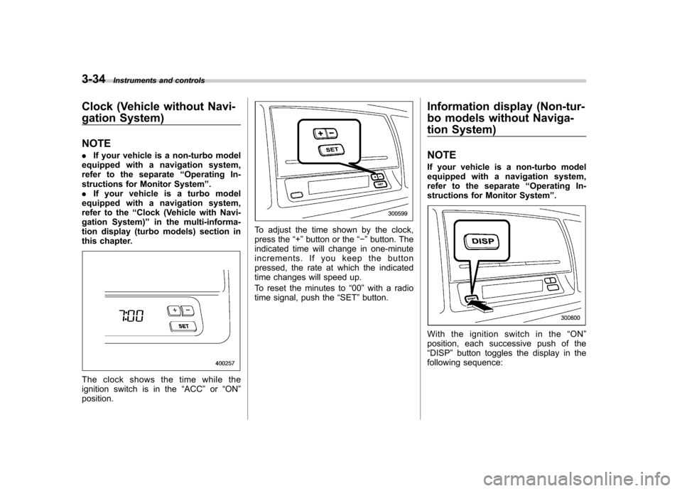
The clock shows the time while the
ignition switch is in the “ACC ”or “ON ”
position.
To adjust the time shown by the clock,
press the “+ ” button or the “� ” button. The
indicated time will change in one-minute
increments. If you keep the button
pressed, the rate at which the indicated
time changes will speed up.
To reset the minutes to “00 ”with a radio
time signal, push the “SET ”button. Information display (Non-tur-
bo models without Naviga-
tion System) NOTE
If your vehicle is a non-turbo model
equipped with a navigation system,
refer to the separate
“Operating In-
structions for Monitor System ”.
With the ignition switch in the “ON ”
position, each successive push of the “ DISP ”button toggles the display in the
following sequence:
Page 182 of 442

!OFF button
The Automatic Climate Control system
turns off (the air conditioner compressor
and fan turn off) when the “OFF ”button is
pressed.
When the “OFF ”button is pressed, the
outside air introduction mode (air inlet
selection OFF) is automatically selected. !
Temperature control dialDriver ’s side
Passenger ’s side
It is possible to make separate tempera-
ture settings for the driver ’ssideand
passenger ’s side. Each temperature setting is shown on the display. With the
dial set at your desired temperature, the
system automatically adjusts the tempera-
ture of air supplied from the outlets such
that the desired temperature is achieved
and maintained.
If the dial is turned fully counterclockwise,
the system gives maximum cooling per-
formance. If the dial is turned fully clock-
wise, the system gives maximum heatingperformance. !
–
Defroster button
To defrost or dehumidify the windshield
and front door windows, push the defros-
ter button “
”. When the “”button is
pushed, regardless whether the air condi-
tioner is operating or not, outside air is
drawn into the passenger compartment, Climate control
4-9
– CONTINUED –
Page 184 of 442

!Air inlet selection button
Select air flow by pushing the air inlet
selection button “/”.
The selected air inlet setting is shown on
the control panel.
(Recirculation): Interior air recirculates
inside the passenger compartment. Use
this position when quickly cooling down
the passenger compartment or to prevent
outside air from entering the passenger
compartment. When the recirculation
mode is selected, a “
”indicator light
appears on the display.
(Outside air): Outside air is drawn into
the passenger compartment. When the
climate control system is operated in the“ AUTO ”mode, this position is selected
automatically. (There is one exception:
When the temperature control dial is turned fully counterclockwise, the recircu-
lation mode is automatically selected.)
When the outside air mode is selected, a“
”
indicator light appears on the dis-
play.
WARNING
Continued operation in the “
”
position may fog up the windows.
Switch to the “
”position as soon
as the outside dusty condition clears.
NOTE
When driving on a dusty road or behind
a vehicle that emits unpleasant exhaust
gases, set the air inlet selection button
to the “
”position.
From time to time, return the air inlet
selection button to the “
”position
to draw outside air into the passenger compartment. &
Temperature sensors
1) Solar sensor
2) Interior air temperature sensor
The automatic climate control system
employs several sensors. These sensors
are delicate. If they are treated incorrectly
and become damaged, the system may
not be able to control the interior tempera-
ture correctly. To avoid damaging the
sensors, observe the following precau-tions: – Do not subject the sensors to impact.
– Keep water away from the sensors.
– Do not cover the sensors.
The sensors are located as follows:– Solar sensor: beside windshield defros-
ter grille Climate control
4-11
– CONTINUED –
Page 395 of 442

11-52Maintenance and service
! Low beam light bulbs
Right-hand side
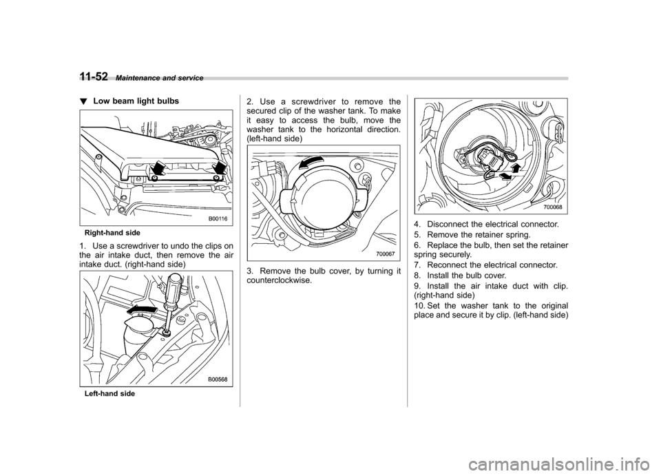
1. Use a screwdriver to undo the clips on
the air intake duct, then remove the air
intake duct. (right-hand side)
Left-hand side 2. Use a screwdriver to remove the
secured clip of the washer tank. To make
it easy to access the bulb, move the
washer tank to the horizontal direction.
(left-hand side)
3. Remove the bulb cover, by turning it counterclockwise.
4. Disconnect the electrical connector.
5. Remove the retainer spring.
6. Replace the bulb, then set the retainer
spring securely.
7. Reconnect the electrical connector.
8. Install the bulb cover.
9. Install the air intake duct with clip.
(right-hand side)
10. Set the washer tank to the original
place and secure it by clip. (left-hand side)
Page 396 of 442

!High beam light bulbs
Right-hand side
1. Use a screwdriver to undo the clips on
the air intake duct, then remove the air
intake duct. (right-hand side)
Left-hand side 2. Use a screwdriver to remove the
secured clip of the washer tank. To make
it easy to access the bulb, move the
washer tank to the horizontal direction.
(left-hand side)
3. Disconnect the electrical connector
from the bulb.
4. Remove the bulb from the headlight
assembly by turning it counterclockwise.
5. Replace the bulb with new one.
6. Reconnect the electrical connector. At
this time, use care not to touch the bulbsurface.
7. To install the bulb to the headlight
assembly, turn it clockwise until it clicks.
8. Install the air intake duct with clip.
(right-hand side)
9. Set the washer tank to the original
place and secure it by clip. (left-hand side) &
Parking light
It may be difficult to replace the bulbs.
Have your SUBARU dealer replace the
bulbs if necessary. & Front turn signal light
It may be difficult to replace the bulbs.
Have your SUBARU dealer replace the
bulbs if necessary. & Front fog light (if equipped)
It may be difficult to replace the bulbs.
Have your SUBARU dealer replace the
bulbs if necessary. Maintenance and service
11-53
– CONTINUED –
Page 397 of 442

11-54Maintenance and service
& Rear combination lights
! Sedan
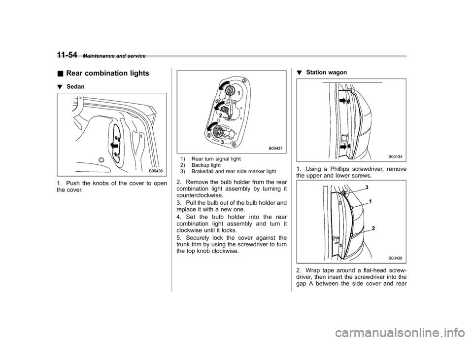
1. Push the knobs of the cover to open
the cover.
1) Rear turn signal light
2) Backup light
3) Brake/tail and rear side marker light
2. Remove the bulb holder from the rear
combination light assembly by turning itcounterclockwise.
3. Pull the bulb out of the bulb holder and
replace it with a new one.
4. Set the bulb holder into the rear
combination light assembly and turn it
clockwise until it locks.
5. Securely lock the cover against the
trunk trim by using the screwdriver to turn
the top knob clockwise. !
Station wagon
1. Using a Phillips screwdriver, remove
the upper and lower screws.
2. Wrap tape around a flat-head screw-
driver, then insert the screwdriver into the
gap A between the side cover and rear