2007 SUBARU OUTBACK key
[x] Cancel search: keyPage 118 of 442

&Tilting/sliding moonroof (Se- dan)
! Tilt function
1) Tilt up
2) Tilt down
The tilting function will only operate when
the moonroof is fully closed.
Push the rear side of the “Tilt ”switch to
raise the moonroof.
Push the front side of the “Tilt ”switch to
lower the moonroof.
Release the switch after the moonroof has
been raised or has been lowered com-
pletely. Pushing the switch continuously
may cause damage to the moonroof. NOTE
One-touch operation does not take
place when the moonroof is tilted up
and down. Push the switch continu-
ously to tilt the moonroof up and down. !
Sliding function
1) Open
2) Close
Push the “Open/Close ”switch rearward to
open the moonroof. The sun shade will
also be opened together with the moon-roof.
Push the “Open/Close ”switch forward to
close the moonroof. The moonroof will
stop halfway if you continue to press on
the switch. Release the switch once and
push it again to close the moonroof completely.
To stop the moonroof at a selected mid-
way position while opening or closing it,
momentarily push the switch to the“
OPEN ”or “CLOSE ”side.
After washing the vehicle or after it rains,
wipe away water on the roof prior to
opening the moonroof to prevent drops
of water from falling into the passengercompartment. ! Anti-entrapment function
When the moonroof senses an object
trapped between its glass and the vehi-cle ’s roof during closure, it automatically
moves back to either of the following
positions according to the point at which
it senses the object: . When the moonroof senses the object
at a point between the halfway stop
position and fully closed position, it moves
back to the halfway stop position and
stops there. . When the moonroof senses the object
at a point between the halfway stop
position and fully open position, it moves
back to the fully open position and stopsthere.
The anti-entrapment function may also be
activated by a strong shock on the moon-
roof even when there is nothing trapped. Keys and doors
2-27
– CONTINUED –
Page 119 of 442

2-28Keys and doors
NOTE
For the sake of safety, it is recom-
mended that you avoid driving with the
moonroof fully opened. ! Sun shade
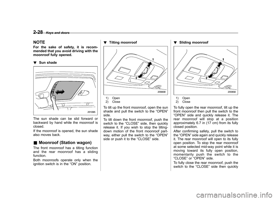
The sun shade can be slid forward or
backward by hand while the moonroof isclosed.
If the moonroof is opened, the sun shade
also moves back. &Moonroof (Station wagon)
The front moonroof has a tilting function
and the rear moonroof has a slidingfunction.
Both moonroofs operate only when the
ignition switch is in the “ON ”position. !
Tilting moonroof
1) Open
2) Close
To tilt up the front moonroof, open the sun
shade and pull the switch to the “OPEN ”
side.
To tilt down the front moonroof, push the
switch to the “CLOSE ”side, then quickly
release it. If you wish to stop the tilting-
down motion of the front moonroof part-
way, either pull the switch to the “OPEN ”
side or push it to the “CLOSE ”side. !
Sliding moonroof1) Open
2) Close
To fully open the rear moonroof, tilt up the
front moonroof then pull the switch to the“ OPEN ”side and quickly release it. The
rear moonroof will stop at a position
approximately 6.7 in (17 cm) from its fully
closed position.
After confirming safety, pull the switch to the “OPEN ”side again and quickly release
it. The rear moonroof will open to its fully
open position. To stop the rear moonroof
at some selected mid-way point while it is
moving toward its fully open position,
momentarily push the switch to the“ CLOSE ”or “OPEN ”side.
To fully close the rear moonroof, push the
switch to the “CLOSE ”side then quickly
Page 120 of 442

release it.
The rear moonroof will stop at a position
approximately 5.9 in (15 cm) before its
fully closed position. After confirming
safety, pull the switch to the“CLOSE ”
side again and quickly release it. The rear
moonroof will fully close. The front moon-
roof can then be fully closed. ! Anti-entrapment function
When the moonroof senses an object
trapped between its glass and during
closure, it automatically moves back by
5.9 in (15 cm) from that point and then
stops. The anti-entrapment function may
also be activated by a strong shock on the
moonroof even when there is nothingtrapped. NOTE . For the sake of safety, it is recom-
mended that you avoid driving with the
moonroof fully opened.. Driving with the moonroof fully open
can cause an annoying sound to gen-
erate at high speeds. If such a condi-
tion has been encountered, use the
moonroof at the initial stop position of
6.7 in (17 cm). !
Sun shade
The sun shade can be slid forward or
backward by hand while the moonroof isclosed.
If the moonroof is opened, the sun shade
also moves back. Keys and doors
2-29
Page 122 of 442

Ignition switch..................................................... 3-3
LOCK .................................................................. 3-3
ACC.................................................................... 3-4
ON...................................................................... 3-4
START ................................................................ 3-4
Key reminder chime ............................................ 3-5
Ignition switch light ............................................. 3-5
Hazard warning flasher ....................................... 3-5
Meters and gauges (Turbo models) ................... 3-5
Combination meter illumination ........................... 3-5
Speedometer ....................................................... 3-6
Tachometer ......................................................... 3-6
Fuel gauge .......................................................... 3-6
Temperature gauge ............................................. 3-7
ECO gauge ......................................................... 3-8
Multi-information display (Turbo models) .......... 3-8
Odometer and trip meter ..................................... 3-9
Current and average fuel consumption ............... 3-10
Outside temperature and journey time ................ 3-11
Driving range on remaining fuel .......................... 3-13
Clock (Vehicle with Navigation System) ............... 3-14
SI-DRIVE display ................................................ 3-14
Warning messages and driver ’s
information ...................................................... 3-15
Meters and gauges (Non-turbo models) ........... 3-18
Combination meter illumination .......................... 3-18
Canceling the function for meter/gauge needle movement upon turning on the ignition switch .............................................................. 3-18
Speedometer ...................................................... 3-18
Odometer ........................................................... 3-19 Double trip meter
............................................... 3-19
Tachometer ....................................................... 3-20
Fuel gauge ........................................................ 3-20
Temperature gauge ............................................ 3-21
Warning and indicator lights ............................. 3-22
Seatbelt warning light and chime ....................... 3-22
SRS airbag system warning light ........................ 3-24
Front passenger ’s frontal airbag ON and OFF
indicators ........................................................ 3-25
CHECK ENGINE warning light/Malfunction indicator lamp ................................................. 3-25
Charge warning light .......................................... 3-26
Oil pressure warning light .................................. 3-26
AT OIL TEMPerature warning light (AT vehicles) .................................................... 3-26
Low tire pressure warning light (if equipped) .................................................... 3-26
ABS warning light .............................................. 3-28
Brake system warning light ................................ 3-28
Low fuel warning light ....................................... 3-29
Door open warning light .................................... 3-29
All-Wheel Drive warning light (AT vehicles) .................................................... 3-30
Vehicle Dynamics Control operation indicator light (if equipped). ............................................ 3-30
Vehicle Dynamics Control warning light (if equipped)/Vehicle Dynamics Control OFF
indicator light (if equipped) .............................. 3-30
Security indicator light ....................................... 3-31
SPORT mode indicator light (if equipped) ........... 3-32
Shift-up indicator light (MT vehicles) (if equipped) .................................................... 3-32
Instruments and controls
3
Page 124 of 442

Ignition switch
WARNING
. Never turn the ignition switch to
“ LOCK ”while the vehicle is
being driven or towed because
that will lock the steering wheel,
preventing steering control. And
when the engine is turned off, it
takes a much greater effort than
usual to steer.
. Before leaving the vehicle, al-
ways remove the key from the
ignition switch for safety and
never allow an unattended child
to remain in the vehicle. Failure
to follow this procedure could
result in injury to a child or
others. Children could operate
the power windows, the sunroof
or other controls or even make
the vehicle move.
CAUTION
Do not attach a large key holder or
key case to either key. If it banged
against your knees or hands while
you were driving, it could turn the
ignition switch from the “ON ”posi- tion to the
“Acc ”or “LOCK ”posi-
tion, thereby stopping the engine.
Also, if the key is attached to a
keyholder or to a large bunch of
other keys, centrifugal force may act
on it as the vehicle moves, resulting
in unwanted turning of the ignitionswitch.
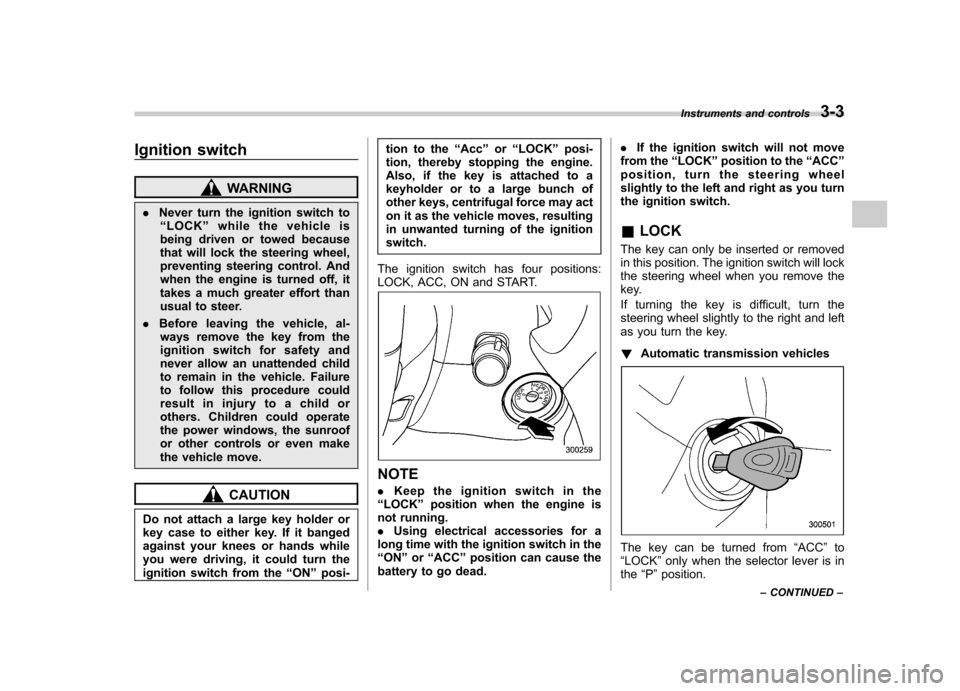
The ignition switch has four positions:
LOCK, ACC, ON and START.
NOTE . Keep the ignition switch in the
“ LOCK ”position when the engine is
not running. . Using electrical accessories for a
long time with the ignition switch in the“ ON ”or “ACC ”position can cause the
battery to go dead. .
If the ignition switch will not move
from the “LOCK ”position to the “ACC ”
position, turn the steering wheel
slightly to the left and right as you turn
the ignition switch.
& LOCK
The key can only be inserted or removed
in this position. The ignition switch will lock
the steering wheel when you remove the
key.
If turning the key is difficult, turn the
steering wheel slightly to the right and left
as you turn the key. ! Automatic transmission vehicles
The key can be turned from “ACC ”to
“ LOCK ”only when the selector lever is in
the “P ”position. Instruments and controls
3-3
– CONTINUED –
Page 125 of 442

3-4Instruments and controls
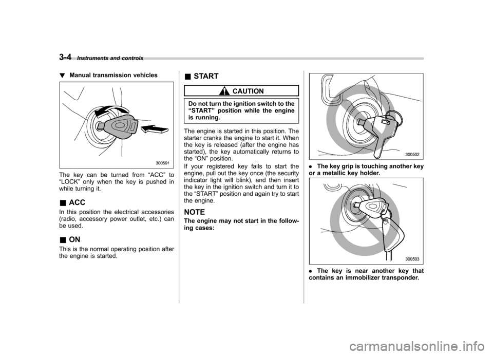
!Manual transmission vehicles
The key can be turned from “ACC ”to
“ LOCK ”only when the key is pushed in
while turning it.
& ACC
In this position the electrical accessories
(radio, accessory power outlet, etc.) can
be used. & ON
This is the normal operating position after
the engine is started. &
START
CAUTION
Do not turn the ignition switch to the “ START ”position while the engine
is running.
The engine is started in this position. The
starter cranks the engine to start it. When
the key is released (after the engine has
started), the key automatically returns to the “ON ”position.
If your registered key fails to start the
engine, pull out the key once (the security
indicator light will blink), and then insert
the key in the ignition switch and turn it tothe “START ”position and again try to start
the engine.
NOTE
The engine may not start in the follow-
ing cases:
. The key grip is touching another key
or a metallic key holder.
. The key is near another key that
contains an immobilizer transponder.
Page 126 of 442

&Key reminder chime
The reminder chime sounds when the driver ’s door opens and the key is in the
“ LOCK ”or “ACC ”positions. The chime
stops when the key is removed from the
ignition switch.
& Ignition switch light
For easy access to the ignition switch in
the dark, the ignition switch light comes on
when any of the doors are opened. The
light remains on for a several seconds and
gradually goes out after all doors are
closed or if the key is inserted in the
ignition switch. Hazard warning flasher
The hazard warning flasher is used to
warn other drivers when you have to park
your vehicle under emergency conditions.
The hazard warning flasher works with the
ignition switch in any position.
To turn on the hazard warning flasher,
push the hazard warning button on the
instrument panel. To turn off the flasher,
push the button again. NOTE
When the hazard warning flasher is on,
the turn signals do not work.Meters and gauges (Turbo
models) NOTE
Liquid-crystal displays are used in
some of the meters and gauges in the
combination meter. You will find their
indications hard to see if you wear
polarized glasses. &
Combination meter illumina- tion
When the ignition switch is turned to the “ ON ”position, the various parts of the
combination meter are illuminated in the
following sequence:
1. Meter needles, gauge needles and
multi-information display (if equipped) lightup.
2. Meter needles and gauge needles
each show MAX position.
3. Meter needles and gauge needles
each show MIN position.
4. Dials in meters and gauges light up.
5. Regular illumination (for driving) be- gins. Instruments and controls
3-5
– CONTINUED –
Page 152 of 442

.The warning light comes on while the
vehicle is running. . If the electrical circuit of the Vehicle
Dynamics Control system itself becomes
faulty, the warning light only comes on. At
this time, the ABS (Anti-lock Brake Sys-
tem) remains fully operational. . The warning light comes on when the
electronic control system of the ABS/
Vehicle Dynamics Control system be-
comes faulty.
The Vehicle Dynamics Control system
provides its ABS control through the
electrical circuit of the ABS system.
Accordingly, if the ABS is inoperative, the
Vehicle Dynamics Control system be-
comes unable to provide ABS control. As
a result, the Vehicle Dynamics Control
system also becomes inoperative, caus-
ing the warning light to come on. Though
both the Vehicle Dynamics Control and
ABS systems are inoperative in this case,
the ordinary functions of the brake system
are still available. You will be safe while
driving with this condition, but have your
vehicle checked at a SUBARU dealer as
soon as possible. NOTE
If the warning light behavior is as
shown in the following, the Vehicle
Dynamics Control system may be con- sidered normal. .
The warning light comes on right
after the engine is started but goes out
immediately, remaining off.. The warning light comes on after
engine startup and goes off while the
vehicle is subsequently being driven.. The warning light comes on during
driving, but it goes out immediately and
remains off. ! Vehicle Dynamics Control OFF in-
dicator light
. It comes on when the Vehicle Dy-
namics Control OFF switch is pressed. . It also comes on when the Vehicle
Dynamics Control system is deactivated.
NOTE . The light may stay on for a while
after the engine has been started,
especially in cold weather. This does
not indicate the existence of a problem.
The light should go out as soon as the
engine has warmed up.. The indicator light comes on when
the engine has developed a problem
and the CHECK ENGINE warning light/
malfunction indicator lamp is on.
The Vehicle Dynamics Control system is
probably faulty under the following condi-
tion. Have your vehicle checked at a SUBARU dealer as soon as possible. .
The light does not go out even after the
lapse of several minutes (the engine has
warmed up) after the engine has started. & Security indicator light
This indicator light shows the status of the
alarm system. It also indicates operation
of the immobilizer system. !Alarm system
It blinks to show the driver the operational
status of the alarm system. For detailed
information, refer to the “Alarm system ”
section in chapter 2. ! Immobilizer system
This light blinks approximately 60 seconds
after the ignition switch is turned from“ ON ”position to the “ACC ”or “LOCK ”
position or immediately after the key is
pulled out. (Refer to the “Door locks ”
section in chapter 2.)
If the indicator light does not flash, it may
indicate that immobilizer system may be
faulty. Contact your nearest SUBARU
dealer immediately.
In the event that an unauthorized key (for
example, an unauthorized duplicate) is
used, the security indicator light comeson. Instruments and controls
3-31
– CONTINUED –