2007 SUBARU OUTBACK ECU
[x] Cancel search: ECUPage 108 of 442

.The 30-second standby time can be
eliminated if you prefer. Have it per-
formed by your SUBARU dealer.. If your vehicle is a Sedan and you
unlock the trunk using the remotetransmitter ’s “
”button with the
alarm system armed, the system will
be temporarily placed in a standby
state. The system will go back to the
surveillance state upon locking thetrunk.. The system is in the standby mode
for a 30-second period after locking the
doors with the remote transmitter. The
security indicator light will flash at
short intervals during this period. . If any of the following actions is
done during the standby period, the
system will not switch to the surveil-
lance state.
.Doors are unlocked using the
remote transmitter. . Any door (including the rear gate
of a Station wagon or the trunk of a
Sedan) is opened. . Ignition switch is turned to the
“ ON ”position. &
Disarming the system
Briefly press the “
”button (for less than
two seconds) on the remote transmitter.
The driver ’s door will unlock, an electronic
chirp will sound twice, the turn signal lights
will flash twice and the indicator light will
go off.
To unlock all other doors and the rear gate
(Station wagon), briefly press the “
”
button a second time within 5 seconds. NOTE
If the interval between the first and
second presses of the “
”button (for
unlocking of all of the doors and the
rear gate) is extremely short, the sys-
tem may not respond.
Or the system can be disarmed by the
following method, too. . Insert the key in the door lock of the
driver ’s door and turn it to the unlock
position. ! Emergency disarming
If you cannot disarm the system using the
transmitter (i.e. the transmitter is lost,
broken or the transmitter battery is too
weak), you can disarm the system without
using the transmitter.
The system can be disarmed if you turn
the ignition switch from the “LOCK ”to the “
ON ”position with a registered key.
Insert the key in the door lock of thedriver ’s door and turn it to the unlock
position.
& Valet mode
When you choose the valet mode, the
alarm system does not operate. In valet
mode, the remote transmitter is used only
for locking and unlocking the doors and
rear gate (Station wagon) and panicactivation.
To enter the valet mode, change the
setting of your vehicle ’s alarm system for
deactivation mode. (Refer to “Activating
and deactivating the alarm system ”in this
section.) The security indicator light will
continue to flash once every three sec-
onds indicating that the system is in the
valet mode.
To exit valet mode, change the setting of
your vehicle ’s alarm system for activation
mode. (Refer to “Activating and deactivat-
ing the alarm system ”in this section.)
& Passive arming
When passive arming mode has been
programmed by the dealer, arming of the
system is automatically accomplished
without using the remote transmitter. Note Keys and doors
2-17
– CONTINUED –
Page 109 of 442

2-18Keys and doors
that in this mode, DOORS MUST BE
MANUALLY LOCKED. !To enter the passive mode
If you wish to program the passive arming
mode, have it done by your SUBARU
dealer. ! Arming the system
CAUTION
In passive mode, the system will
automatically activate the alarm but
WILL NOT automatically lock the
doors. In order to lock the doors
you must either lock them as in-
dicated in step 4 below or with the
key once they have been closed.
Failure to lock the doors manually
will result in a higher security risk.
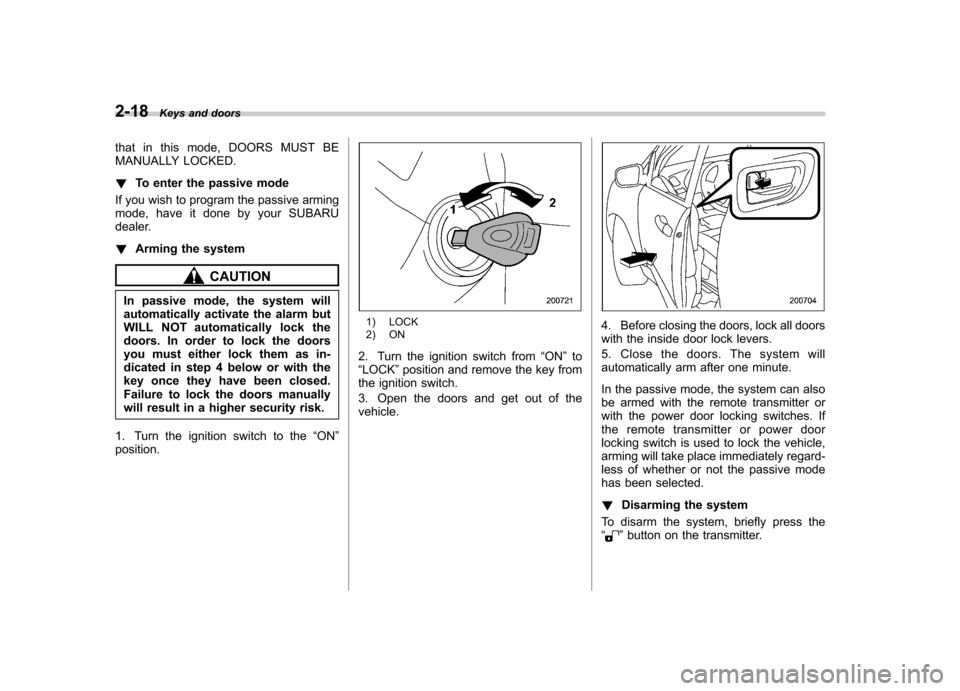
1. Turn the ignition switch to the “ON ”
position.
1) LOCK
2) ON
2. Turn the ignition switch from “ON ”to
“ LOCK ”position and remove the key from
the ignition switch.
3. Open the doors and get out of the vehicle.4. Before closing the doors, lock all doors
with the inside door lock levers.
5. Close the doors. The system will
automatically arm after one minute.
In the passive mode, the system can also
be armed with the remote transmitter or
with the power door locking switches. If
the remote transmitter or power door
locking switch is used to lock the vehicle,
arming will take place immediately regard-
less of whether or not the passive mode
has been selected. ! Disarming the system
To disarm the system, briefly press the “
” button on the transmitter.
Page 110 of 442

&Tripped sensor identification
The security indicator light flashes when
the alarm system has been triggered.
Also, the number of flashes indicates the
location of unauthorized intrusion or the
severity of impact on the vehicle. . When the ignition switch is turned to
the “ON ”position, the indicator light will
light for 1 second and then flash as follows:
When a door or rear gate (Station
wagon) was opened: 5 times
When the trunk (Sedan) was opened:
4 times
When a strong impact or multiple
impacts were sensed: twice (only
vehicles with shock sensors (dealeroption))
When a light impact was sensed: once
(only vehicles with shock sensors
(dealer option))
& Shock sensors (dealer op- tion)
The shock sensors trigger the alarm
system when they sense impacts applied
to the vehicle and when any of their
electric wires is cut. The alarm system
causes the horn to sound and the turn
signal lights to flash for a short time when
the sensed impact is weak, but it warns of a strong impact or multiple impacts by
sounding the horn and flashing the turn
signal lights, both lasting approximately 30seconds.
If you desire, your SUBARU dealer can
connect them and set them for activation
or deactivation.
NOTE . The shock sensors are not always
able to sense impacts caused by break-
ing in, and cannot sense an impact that
does not cause vibration (such as
breaking the glass using a rescuehammer).. The shock sensors may sense vi-
bration like those shown in the follow-
ing and trigger the alarm system.
Select the settings of the alarm system
and shock sensors appropriately de-
pending on where you usually park
your vehicle.Example:
Vibration from construction site
Vibration in multistory car park
Vibration from trains
. You can have the sensitivity of the
shock sensors adjusted to your pre-
ference by your SUBARU dealer. Child safety locks
WARNING
Always use the child safety lock
whenever a child rides in the rear
seat. Serious injury could result if a
child accidentally opened the door
and fell out.
Each rear door has a child safety lock that
prevents the doors from being opened
even if the inside door handle is pulled.
When the child safety lock lever is in the
lock position, the door cannot be opened
from inside regardless of the position of
the inner door handle lock lever. The door
can only be opened from the outside. Keys and doors
2-19
Page 115 of 442

2-24Keys and doors
WARNING
Never allow any child to get in the
trunk and play with the release
handle. If the driver starts the vehi-
cle without knowing that a child is
inside the trunk and the child opens
the lid using the release handle, the
child could fall out and be killed or
seriously injured.
CAUTION
. Do not close the lid while grip-
ping the release handle. The
handle may be damaged.
. Do not use the handle as a hook
to fasten straps or ropes to
secure your cargo in the trunk.
Such use may result in damage
of the handle.
. Load the trunk so that cargo can
not strike the release handle. If
the cargo hits the handle while
the vehicle is being driven, the
handle may be pushed down and
the trunk lid may open. That may
cause cargo to fall out of the
trunk, which could create a traffic
safety hazard. !
Inspection
Perform the following steps at least twice
a year to check the release handle for
correct operation.
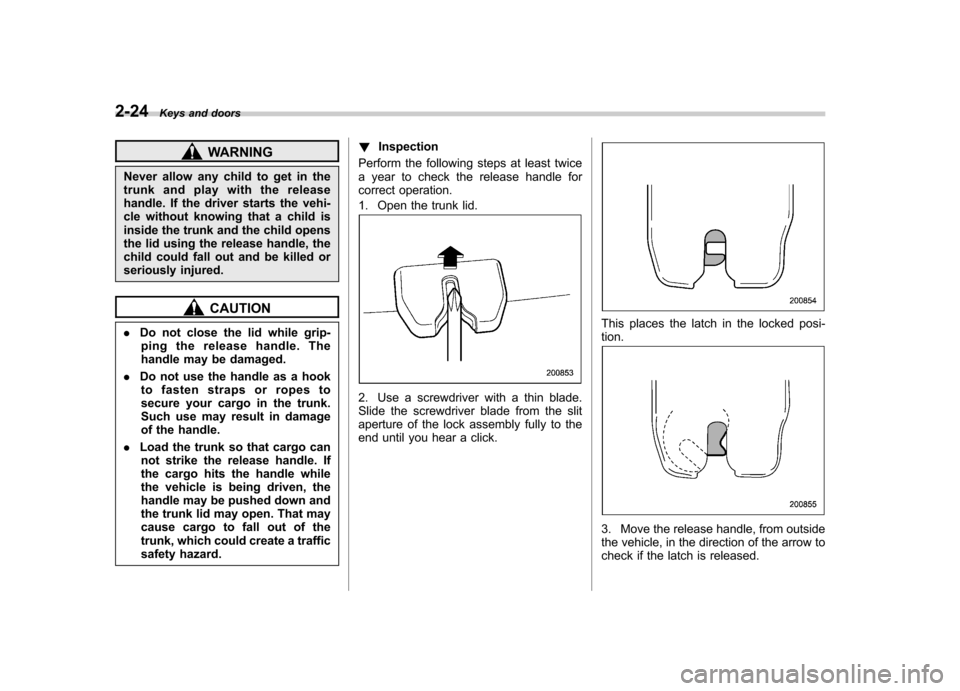
1. Open the trunk lid.
2. Use a screwdriver with a thin blade.
Slide the screwdriver blade from the slit
aperture of the lock assembly fully to the
end until you hear a click.
This places the latch in the locked posi- tion.
3. Move the release handle, from outside
the vehicle, in the direction of the arrow to
check if the latch is released.
Page 122 of 442

Ignition switch..................................................... 3-3
LOCK .................................................................. 3-3
ACC.................................................................... 3-4
ON...................................................................... 3-4
START ................................................................ 3-4
Key reminder chime ............................................ 3-5
Ignition switch light ............................................. 3-5
Hazard warning flasher ....................................... 3-5
Meters and gauges (Turbo models) ................... 3-5
Combination meter illumination ........................... 3-5
Speedometer ....................................................... 3-6
Tachometer ......................................................... 3-6
Fuel gauge .......................................................... 3-6
Temperature gauge ............................................. 3-7
ECO gauge ......................................................... 3-8
Multi-information display (Turbo models) .......... 3-8
Odometer and trip meter ..................................... 3-9
Current and average fuel consumption ............... 3-10
Outside temperature and journey time ................ 3-11
Driving range on remaining fuel .......................... 3-13
Clock (Vehicle with Navigation System) ............... 3-14
SI-DRIVE display ................................................ 3-14
Warning messages and driver ’s
information ...................................................... 3-15
Meters and gauges (Non-turbo models) ........... 3-18
Combination meter illumination .......................... 3-18
Canceling the function for meter/gauge needle movement upon turning on the ignition switch .............................................................. 3-18
Speedometer ...................................................... 3-18
Odometer ........................................................... 3-19 Double trip meter
............................................... 3-19
Tachometer ....................................................... 3-20
Fuel gauge ........................................................ 3-20
Temperature gauge ............................................ 3-21
Warning and indicator lights ............................. 3-22
Seatbelt warning light and chime ....................... 3-22
SRS airbag system warning light ........................ 3-24
Front passenger ’s frontal airbag ON and OFF
indicators ........................................................ 3-25
CHECK ENGINE warning light/Malfunction indicator lamp ................................................. 3-25
Charge warning light .......................................... 3-26
Oil pressure warning light .................................. 3-26
AT OIL TEMPerature warning light (AT vehicles) .................................................... 3-26
Low tire pressure warning light (if equipped) .................................................... 3-26
ABS warning light .............................................. 3-28
Brake system warning light ................................ 3-28
Low fuel warning light ....................................... 3-29
Door open warning light .................................... 3-29
All-Wheel Drive warning light (AT vehicles) .................................................... 3-30
Vehicle Dynamics Control operation indicator light (if equipped). ............................................ 3-30
Vehicle Dynamics Control warning light (if equipped)/Vehicle Dynamics Control OFF
indicator light (if equipped) .............................. 3-30
Security indicator light ....................................... 3-31
SPORT mode indicator light (if equipped) ........... 3-32
Shift-up indicator light (MT vehicles) (if equipped) .................................................... 3-32
Instruments and controls
3
Page 125 of 442

3-4Instruments and controls
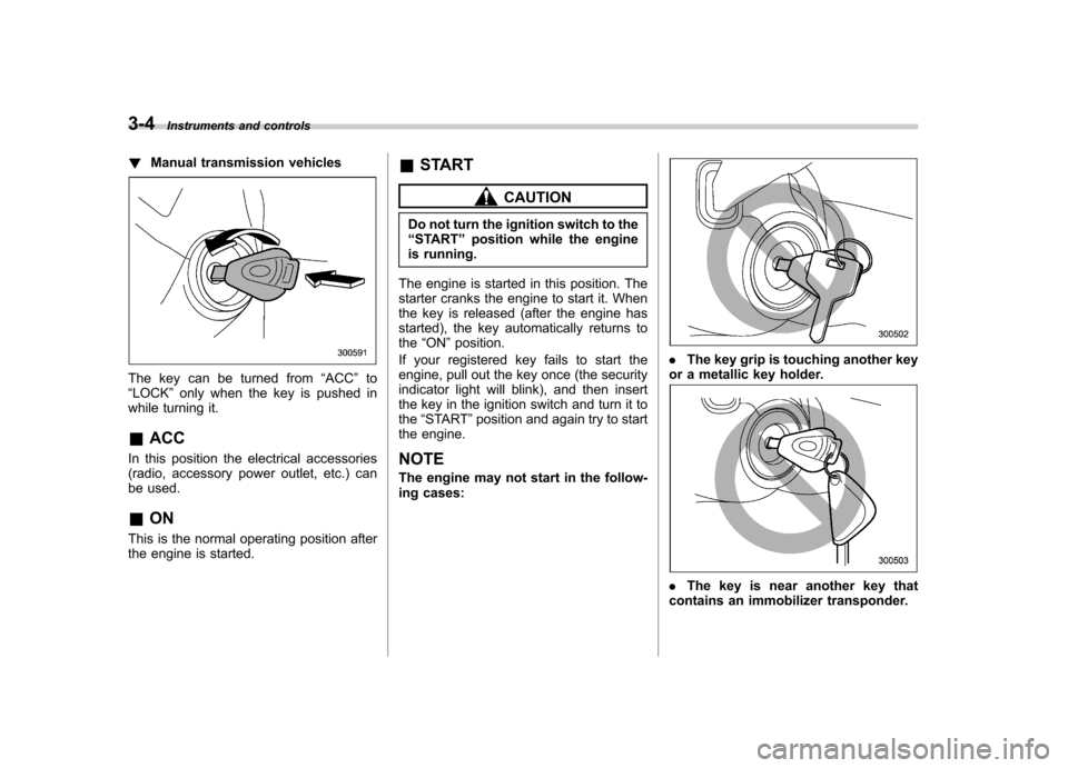
!Manual transmission vehicles
The key can be turned from “ACC ”to
“ LOCK ”only when the key is pushed in
while turning it.
& ACC
In this position the electrical accessories
(radio, accessory power outlet, etc.) can
be used. & ON
This is the normal operating position after
the engine is started. &
START
CAUTION
Do not turn the ignition switch to the “ START ”position while the engine
is running.
The engine is started in this position. The
starter cranks the engine to start it. When
the key is released (after the engine has
started), the key automatically returns to the “ON ”position.
If your registered key fails to start the
engine, pull out the key once (the security
indicator light will blink), and then insert
the key in the ignition switch and turn it tothe “START ”position and again try to start
the engine.
NOTE
The engine may not start in the follow-
ing cases:
. The key grip is touching another key
or a metallic key holder.
. The key is near another key that
contains an immobilizer transponder.
Page 145 of 442

3-24Instruments and controls
.Do not install any accessory such as a
table or TV onto the seatback. . Do not store a heavy load in the
seatback pocket.. Do not allow the rear seat occupant to
place his/her hands or legs on the front passenger ’s seatback, or allow him/her to
pull the seatback. . Do not use front seats with their back-
ward-forward position and seatback not
being locked into place securely. If any of
them are not locked securely, adjust them
again. For adjusting procedure, refer tothe “Manual seat ”in the front seats section
in chapter 1 in this owner ’s manual.
(Models equipped with manual seats only)
If the seatbelt warning device for the front passenger ’s seat does not function cor-
rectly (e.g., it is activated even when the
front passenger ’s seat is empty or it is
deactivated even when the front passen-
ger has not fastened his/her seatbelt),
take the following actions. . Ensure that no article is placed on the
seat other than a child restraint system
and its child occupant. . Ensure that there is no article left in the
seatback pocket.. Ensure that the backward-forward po-
sition and seatback of front passenger ’s
seat are locked into place securely by moving the seat back and forth. (Models
equipped with manual seats only)
If still the seatbelt warning device for front passenger
’s seat does not function cor-
rectly after taking relevant corrective ac-
tions described above, immediately
contact your SUBARU dealer for aninspection.
& SRS airbag system
warning light
When the ignition switch is turned to the “ON ”position, the SRS airbag system
warning light will come on for approxi-
mately seven seconds and go out. This
shows the SRS frontal airbag and SRS
side airbag and SRS curtain airbag and
seatbelt pretensioners are in normal op-eration.
WARNING
If the warning light exhibits any of
the following conditions, there may
be a malfunction in the seatbelt
pretensioners and/or SRS airbag
system. Immediately take your vehi-
cle to your nearest SUBARU dealer
to have the system checked. Unless
checked and properly repaired, the
seatbelt pretensioners and/or SRS airbags will operate improperly (e.g.
SRS airbags may inflate in a very
minor collision or not inflate in a
severe collision), which may in-
crease the risk of injury. .
Flashing or flickering of the warn-
ing light
. No illumination of the warning
light when the ignition switch is
first turned to the “ON ”position
. Continuous illumination of the
warning light
. Illumination of the warning light
while driving
Page 152 of 442

.The warning light comes on while the
vehicle is running. . If the electrical circuit of the Vehicle
Dynamics Control system itself becomes
faulty, the warning light only comes on. At
this time, the ABS (Anti-lock Brake Sys-
tem) remains fully operational. . The warning light comes on when the
electronic control system of the ABS/
Vehicle Dynamics Control system be-
comes faulty.
The Vehicle Dynamics Control system
provides its ABS control through the
electrical circuit of the ABS system.
Accordingly, if the ABS is inoperative, the
Vehicle Dynamics Control system be-
comes unable to provide ABS control. As
a result, the Vehicle Dynamics Control
system also becomes inoperative, caus-
ing the warning light to come on. Though
both the Vehicle Dynamics Control and
ABS systems are inoperative in this case,
the ordinary functions of the brake system
are still available. You will be safe while
driving with this condition, but have your
vehicle checked at a SUBARU dealer as
soon as possible. NOTE
If the warning light behavior is as
shown in the following, the Vehicle
Dynamics Control system may be con- sidered normal. .
The warning light comes on right
after the engine is started but goes out
immediately, remaining off.. The warning light comes on after
engine startup and goes off while the
vehicle is subsequently being driven.. The warning light comes on during
driving, but it goes out immediately and
remains off. ! Vehicle Dynamics Control OFF in-
dicator light
. It comes on when the Vehicle Dy-
namics Control OFF switch is pressed. . It also comes on when the Vehicle
Dynamics Control system is deactivated.
NOTE . The light may stay on for a while
after the engine has been started,
especially in cold weather. This does
not indicate the existence of a problem.
The light should go out as soon as the
engine has warmed up.. The indicator light comes on when
the engine has developed a problem
and the CHECK ENGINE warning light/
malfunction indicator lamp is on.
The Vehicle Dynamics Control system is
probably faulty under the following condi-
tion. Have your vehicle checked at a SUBARU dealer as soon as possible. .
The light does not go out even after the
lapse of several minutes (the engine has
warmed up) after the engine has started. & Security indicator light
This indicator light shows the status of the
alarm system. It also indicates operation
of the immobilizer system. !Alarm system
It blinks to show the driver the operational
status of the alarm system. For detailed
information, refer to the “Alarm system ”
section in chapter 2. ! Immobilizer system
This light blinks approximately 60 seconds
after the ignition switch is turned from“ ON ”position to the “ACC ”or “LOCK ”
position or immediately after the key is
pulled out. (Refer to the “Door locks ”
section in chapter 2.)
If the indicator light does not flash, it may
indicate that immobilizer system may be
faulty. Contact your nearest SUBARU
dealer immediately.
In the event that an unauthorized key (for
example, an unauthorized duplicate) is
used, the security indicator light comeson. Instruments and controls
3-31
– CONTINUED –