2007 SUBARU OUTBACK weight
[x] Cancel search: weightPage 71 of 442
1-44Seat, seatbelt and SRS airbags
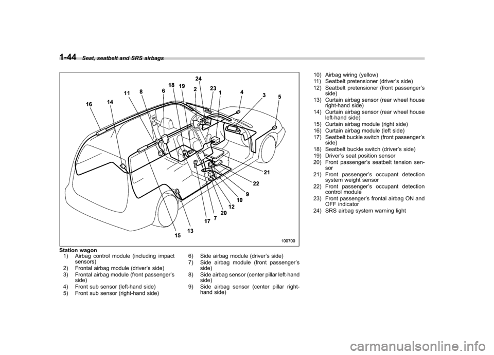
Station wagon
1) Airbag control module (including impact sensors)
2) Frontal airbag module (driver ’s side)
3) Frontal airbag module (front passenger ’s
side)
4) Front sub sensor (left-hand side)
5) Front sub sensor (right-hand side) 6) Side airbag module (driver
’s side)
7) Side airbag module (front passenger ’s
side)
8) Side airbag sensor (center pillar left-hand side)
9) Side airbag sensor (center pillar right- hand side) 10) Airbag wiring (yellow)
11) Seatbelt pretensioner (driver
’s side)
12) Seatbelt pretensioner (front passenger ’s
side)
13) Curtain airbag sensor (rear wheel house right-hand side)
14) Curtain airbag sensor (rear wheel house left-hand side)
15) Curtain airbag module (right side)
16) Curtain airbag module (left side)
17) Seatbelt buckle switch (front passenger ’s
side)
18) Seatbelt buckle switch (driver ’s side)
19) Driver ’s seat position sensor
20) Front passenger ’s seatbelt tension sen-
sor
21) Front passenger ’s occupant detection
system weight sensor
22) Front passenger ’s occupant detection
control module
23) Front passenger ’s frontal airbag ON and
OFF indicator
24) SRS airbag system warning light
Page 74 of 442
WARNING
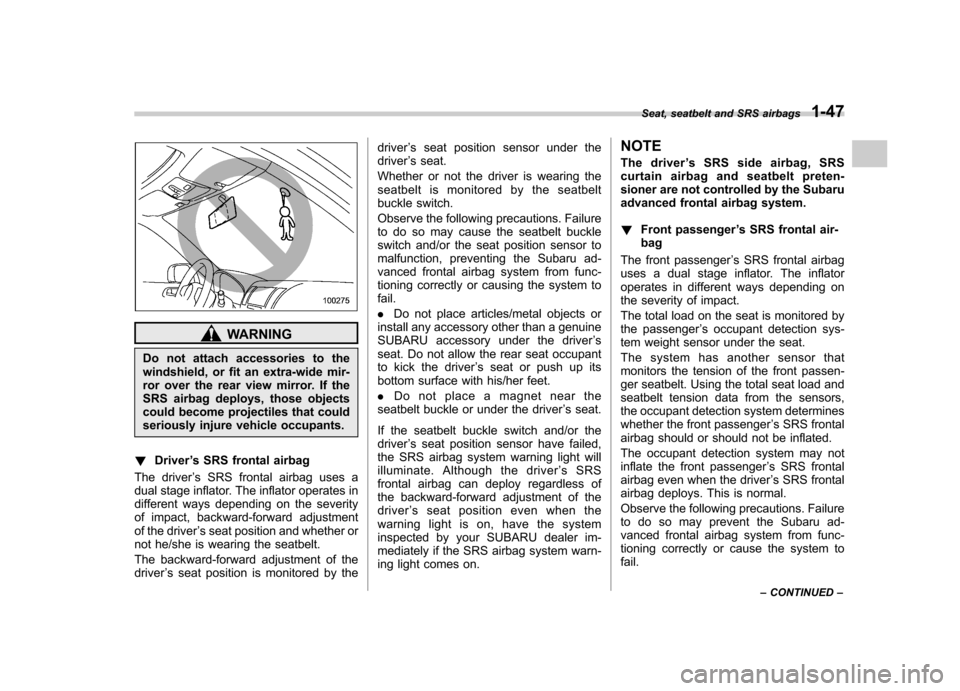
Do not attach accessories to the
windshield, or fit an extra-wide mir-
ror over the rear view mirror. If the
SRS airbag deploys, those objects
could become projectiles that could
seriously injure vehicle occupants.
! Driver ’s SRS frontal airbag
The driver ’s SRS frontal airbag uses a
dual stage inflator. The inflator operates in
different ways depending on the severity
of impact, backward-forward adjustment
of the driver ’s seat position and whether or
not he/she is wearing the seatbelt.
The backward-forward adjustment of the driver ’s seat position is monitored by the driver
’s seat position sensor under the
driver ’s seat.
Whether or not the driver is wearing the
seatbelt is monitored by the seatbelt
buckle switch.
Observe the following precautions. Failure
to do so may cause the seatbelt buckle
switch and/or the seat position sensor to
malfunction, preventing the Subaru ad-
vanced frontal airbag system from func-
tioning correctly or causing the system tofail. . Do not place articles/metal objects or
install any accessory other than a genuine
SUBARU accessory under the driver ’s
seat. Do not allow the rear seat occupant
to kick the driver ’s seat or push up its
bottom surface with his/her feet. . Do not place a magnet near the
seatbelt buckle or under the driver ’s seat.
If the seatbelt buckle switch and/or the driver ’s seat position sensor have failed,
the SRS airbag system warning light will
illuminate. Although the driver ’sSRS
frontal airbag can deploy regardless of
the backward-forward adjustment of the
driver ’s seat position even when the
warning light is on, have the system
inspected by your SUBARU dealer im-
mediately if the SRS airbag system warn-
ing light comes on. NOTE
The driver
’s SRS side airbag, SRS
curtain airbag and seatbelt preten-
sioner are not controlled by the Subaru
advanced frontal airbag system. ! Front passenger ’s SRS frontal air-
bag
The front passenger ’s SRS frontal airbag
uses a dual stage inflator. The inflator
operates in different ways depending on
the severity of impact.
The total load on the seat is monitored by
the passenger ’s occupant detection sys-
tem weight sensor under the seat.
The system has another sensor that
monitors the tension of the front passen-
ger seatbelt. Using the total seat load and
seatbelt tension data from the sensors,
the occupant detection system determines
whether the front passenger ’s SRS frontal
airbag should or should not be inflated.
The occupant detection system may not
inflate the front passenger ’s SRS frontal
airbag even when the driver ’s SRS frontal
airbag deploys. This is normal.
Observe the following precautions. Failure
to do so may prevent the Subaru ad-
vanced frontal airbag system from func-
tioning correctly or cause the system to fail. Seat, seatbelt and SRS airbags
1-47
– CONTINUED –
Page 79 of 442
1-52Seat, seatbelt and SRS airbags
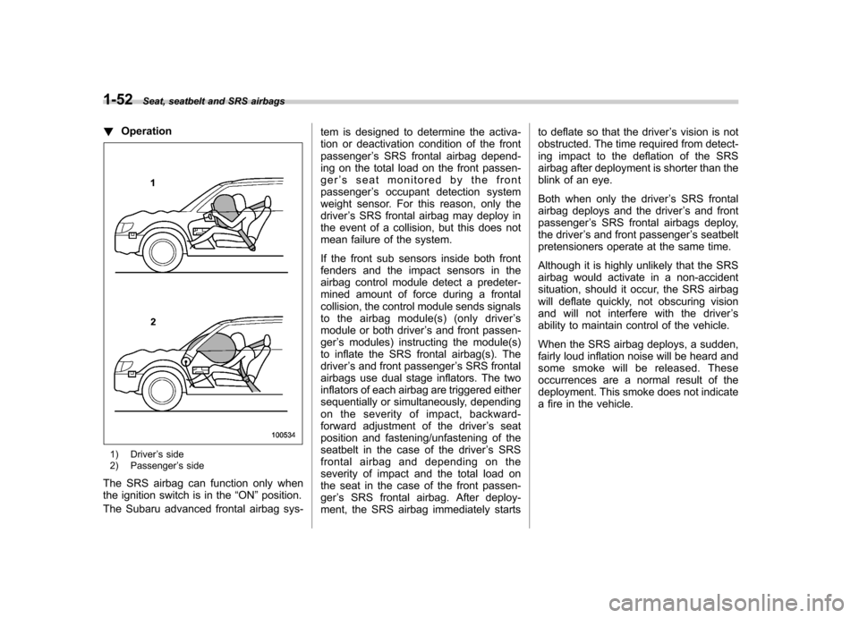
! Operation
1) Driver ’s side
2) Passenger ’s side
The SRS airbag can function only when
the ignition switch is in the “ON ”position.
The Subaru advanced frontal airbag sys- tem is designed to determine the activa-
tion or deactivation condition of the frontpassenger
’s SRS frontal airbag depend-
ing on the total load on the front passen-
ger ’s seat monitored by the front
passenger ’s occupant detection system
weight sensor. For this reason, only thedriver ’s SRS frontal airbag may deploy in
the event of a collision, but this does not
mean failure of the system.
If the front sub sensors inside both front
fenders and the impact sensors in the
airbag control module detect a predeter-
mined amount of force during a frontal
collision, the control module sends signals
to the airbag module(s) (only driver ’s
module or both driver ’s and front passen-
ger ’s modules) instructing the module(s)
to inflate the SRS frontal airbag(s). Thedriver ’s and front passenger ’s SRS frontal
airbags use dual stage inflators. The two
inflators of each airbag are triggered either
sequentially or simultaneously, depending
on the severity of impact, backward-
forward adjustment of the driver ’s seat
position and fastening/unfastening of the
seatbelt in the case of the driver ’s SRS
frontal airbag and depending on the
severity of impact and the total load on
the seat in the case of the front passen-ger ’s SRS frontal airbag. After deploy-
ment, the SRS airbag immediately starts to deflate so that the driver
’s vision is not
obstructed. The time required from detect-
ing impact to the deflation of the SRS
airbag after deployment is shorter than the
blink of an eye.
Both when only the driver ’s SRS frontal
airbag deploys and the driver ’s and front
passenger ’s SRS frontal airbags deploy,
the driver ’s and front passenger ’s seatbelt
pretensioners operate at the same time.
Although it is highly unlikely that the SRS
airbag would activate in a non-accident
situation, should it occur, the SRS airbag
will deflate quickly, not obscuring vision
and will not interfere with the driver ’s
ability to maintain control of the vehicle.
When the SRS airbag deploys, a sudden,
fairly loud inflation noise will be heard and
some smoke will be released. These
occurrences are a normal result of the
deployment. This smoke does not indicate
a fire in the vehicle.
Page 89 of 442
1-62Seat, seatbelt and SRS airbags
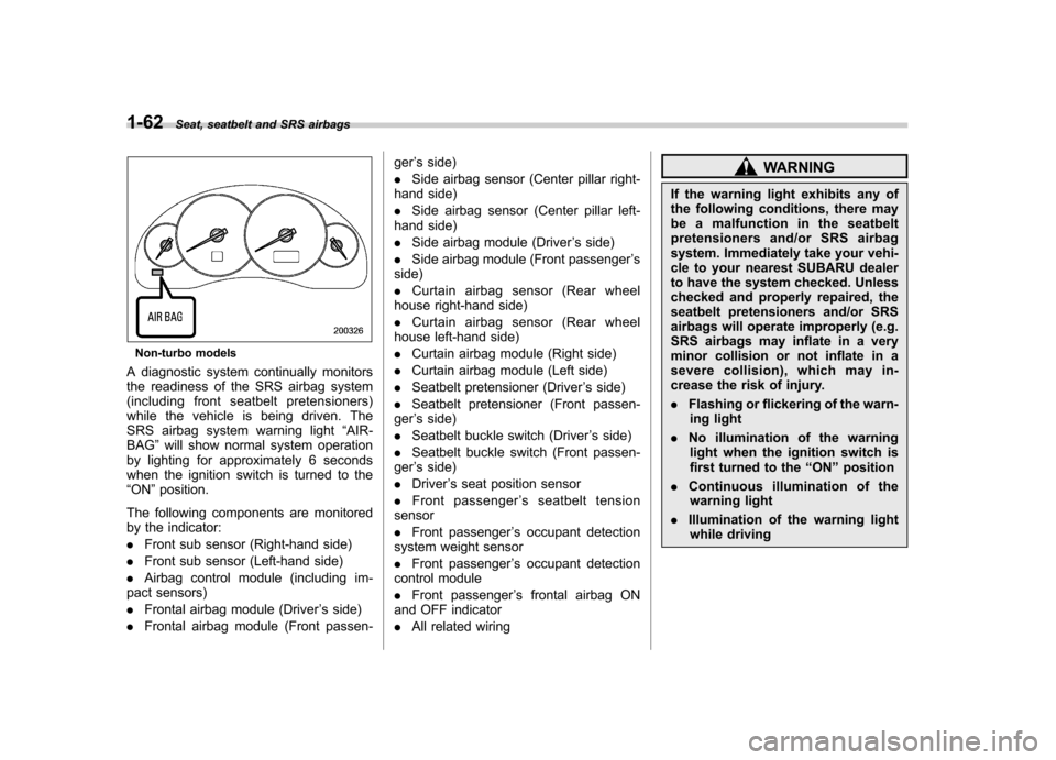
Non-turbo models
A diagnostic system continually monitors
the readiness of the SRS airbag system
(including front seatbelt pretensioners)
while the vehicle is being driven. The
SRS airbag system warning light “AIR-
BAG ”will show normal system operation
by lighting for approximately 6 seconds
when the ignition switch is turned to the“ ON ”position.
The following components are monitored
by the indicator: . Front sub sensor (Right-hand side)
. Front sub sensor (Left-hand side)
. Airbag control module (including im-
pact sensors). Frontal airbag module (Driver ’s side)
. Frontal airbag module (Front passen- ger
’s side)
. Side airbag sensor (Center pillar right-
hand side). Side airbag sensor (Center pillar left-
hand side). Side airbag module (Driver ’s side)
. Side airbag module (Front passenger ’s
side). Curtain airbag sensor (Rear wheel
house right-hand side). Curtain airbag sensor (Rear wheel
house left-hand side). Curtain airbag module (Right side)
. Curtain airbag module (Left side)
. Seatbelt pretensioner (Driver ’s side)
. Seatbelt pretensioner (Front passen-
ger ’s side)
. Seatbelt buckle switch (Driver ’s side)
. Seatbelt buckle switch (Front passen-
ger ’s side)
. Driver ’s seat position sensor
. Front passenger ’s seatbelt tension
sensor. Front passenger ’s occupant detection
system weight sensor. Front passenger ’s occupant detection
control module. Front passenger ’s frontal airbag ON
and OFF indicator. All related wiring
WARNING
If the warning light exhibits any of
the following conditions, there may
be a malfunction in the seatbelt
pretensioners and/or SRS airbag
system. Immediately take your vehi-
cle to your nearest SUBARU dealer
to have the system checked. Unless
checked and properly repaired, the
seatbelt pretensioners and/or SRS
airbags will operate improperly (e.g.
SRS airbags may inflate in a very
minor collision or not inflate in a
severe collision), which may in-
crease the risk of injury. . Flashing or flickering of the warn-
ing light
. No illumination of the warning
light when the ignition switch is
first turned to the “ON ”position
. Continuous illumination of the
warning light
. Illumination of the warning light
while driving
Page 228 of 442
WARNING
Do not place anything on the ex-
tended cover. Putting excessive
weight on the extended cover can
break it and an object on the cover
could tumble forward in the event of
a sudden stop or collision. This
could cause serious injury.
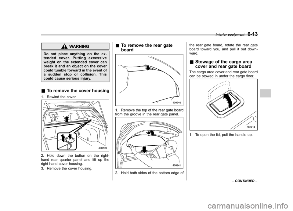
& To remove the cover housing
1. Rewind the cover.
2. Hold down the button on the right-
hand rear quarter panel and lift up the
right-hand cover housing.
3. Remove the cover housing. &
To remove the rear gate board
1. Remove the top of the rear gate board
from the groove in the rear gate panel.
2. Hold both sides of the bottom edge of the rear gate board, rotate the rear gate
board toward you, and pull it out down-ward. &
Stowage of the cargo area
cover and rear gate board
The cargo area cover and rear gate board
can be stowed in under the cargo floor.
1. To open the lid, pull the handle up. Interior equipment
6-13
– CONTINUED –
Page 288 of 442

New vehicle break-in driving–the first
1,000 miles (1,600 km) ..................................... 8-2
Fuel economy hints ............................................ 8-2
Engine exhaust gas (Carbon monoxide) ........... 8-2
Catalytic converter .............................................. 8-3
Periodic inspections ........................................... 8-4
Driving in foreign countries ............................... 8-4
Driving tips for AWD vehicles ............................ 8-5
Off road driving ................................................... 8-6
All AWD models except OUTBACK ...................... 8-6
OUTBACK ........................................................... 8-6
Winter driving ...................................................... 8-8
Operation during cold weather ............................. 8-8
Driving on snowy and icy roads .......................... 8-9
Corrosion protection .......................................... 8-10
Snow tires ......................................................... 8-10 Tire chains
........................................................ 8-12
Rocking the vehicle ........................................... 8-13
Loading your vehicle ......................................... 8-13
Vehicle capacity weight ...................................... 8-14
GVWR and GAWR (Gross Vehicle Weight Rating and Gross Axle Weight Rating) ........................ 8-15
Roof rail and crossbar (if equipped) ................... 8-15
Trailer hitch (if equipped) .................................. 8-19
Connecting a trailer ........................................... 8-20
When you do not tow a trailer .. .......................... 8-21
Trailer towing ..................................................... 8-21
Warranties and maintenance .............................. 8-21
Maximum load limits .......................................... 8-22
Trailer hitches .................................................... 8-25
Connecting a trailer ........................................... 8-26
Trailer towing tips .............................................. 8-27Driving tips
8
Page 301 of 442
8-14Driving tips
possible.
. When you carry something inside
the vehicle, secure it whenever
you can to prevent it from being
thrown around inside the vehicle
during sudden stops, sharp turns
or in an accident.
. Do not pile heavy loads on the
roof. These loads raise the vehi-cle ’s center of gravity and make it
more prone to tip over.
. Secure lengthy items properly to
prevent them from shooting for-
ward and causing serious injury
during a sudden stop.
. Never exceed the maximum load
limit. If you do, some parts on
your vehicle can break, or it can
change the way your vehicle
handles. This could result in loss
of control and cause personal
injury. Also, overloading can
shorten the life of your vehicle. .
Do not place anything on the rear
shelf behind the rear seatback
(for Sedan) or the extended lug-
gage cover (for Station wagon).
Such items could tumble forward
in the event of a sudden stop or a
collision. This could cause ser-
ious injury.
CAUTION
Do not carry spray cans, containers
with flammable or corrosive liquids
or any other dangerous items inside
the vehicle.
NOTE
For better fuel economy, do not carry
unneeded cargo. &
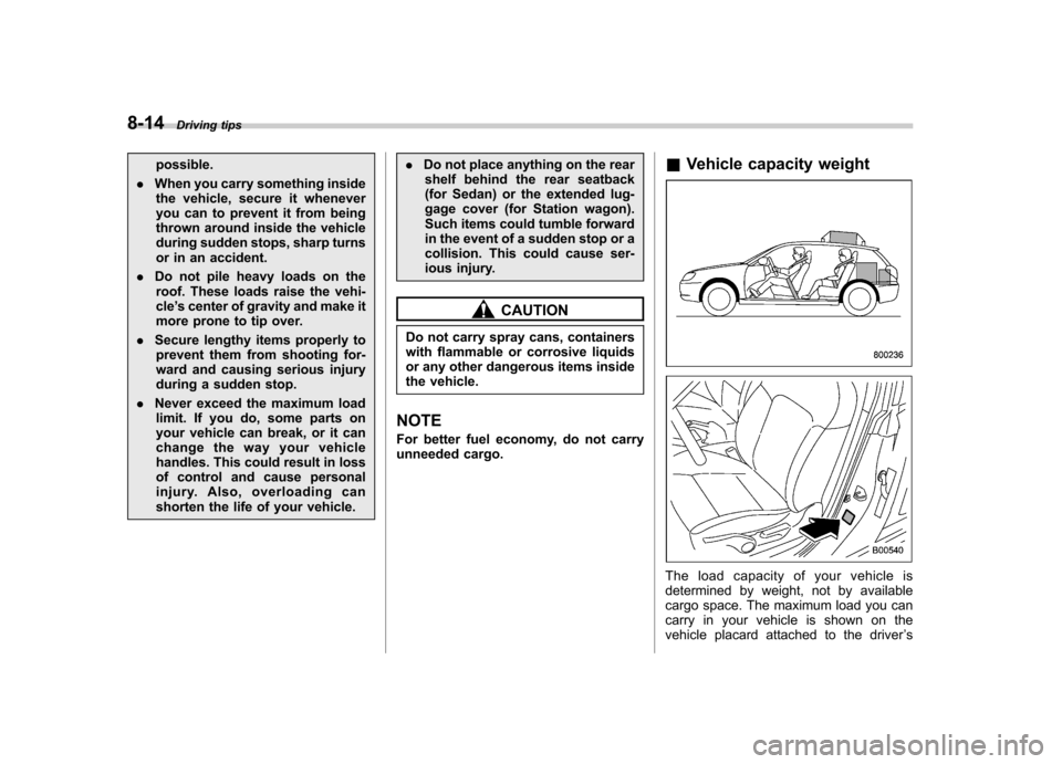
Vehicle capacity weight
The load capacity of your vehicle is
determined by weight, not by available
cargo space. The maximum load you can
carry in your vehicle is shown on the
vehicle placard attached to the driver ’s
Page 302 of 442
side door pillar. It includes the total weight
of the driver and all passengers and their
belongings, any optional equipment such
as a trailer hitch, roof rack or bike carrier,
etc., and the tongue load of a trailer. &GVWR and GAWR (Gross
Vehicle Weight Rating and
Gross Axle Weight Rating)
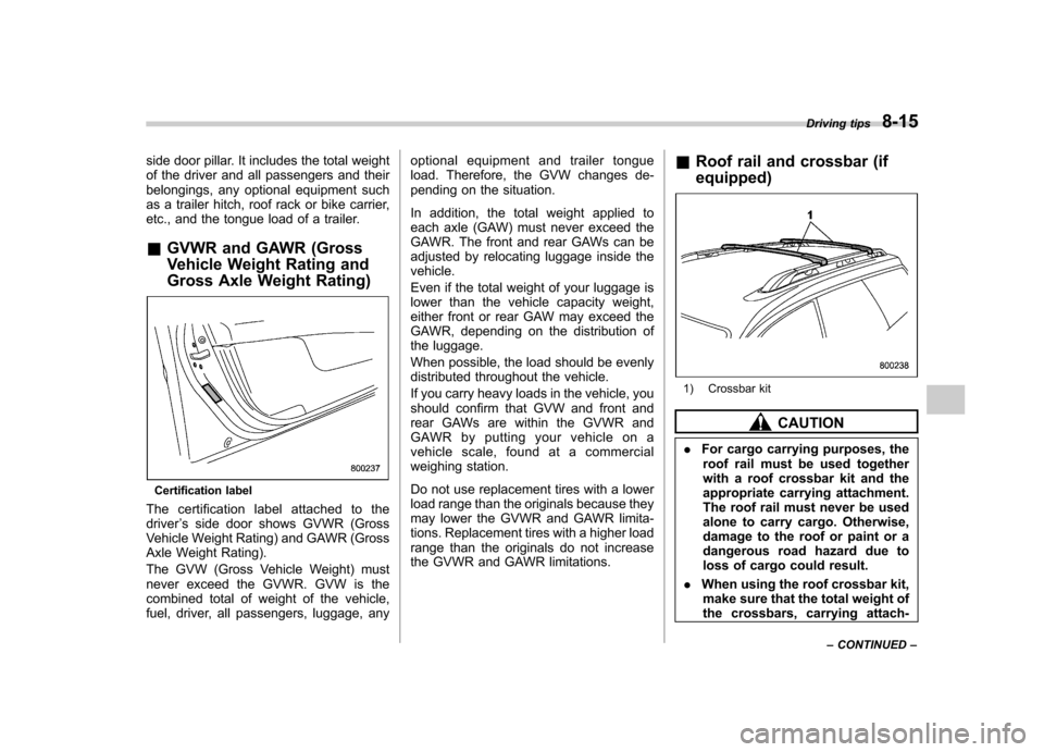
Certification label
The certification label attached to the driver ’s side door shows GVWR (Gross
Vehicle Weight Rating) and GAWR (Gross
Axle Weight Rating).
The GVW (Gross Vehicle Weight) must
never exceed the GVWR. GVW is the
combined total of weight of the vehicle,
fuel, driver, all passengers, luggage, any optional equipment and trailer tongue
load. Therefore, the GVW changes de-
pending on the situation.
In addition, the total weight applied to
each axle (GAW) must never exceed the
GAWR. The front and rear GAWs can be
adjusted by relocating luggage inside thevehicle.
Even if the total weight of your luggage is
lower than the vehicle capacity weight,
either front or rear GAW may exceed the
GAWR, depending on the distribution of
the luggage.
When possible, the load should be evenly
distributed throughout the vehicle.
If you carry heavy loads in the vehicle, you
should confirm that GVW and front and
rear GAWs are within the GVWR and
GAWR by putting your vehicle on a
vehicle scale, found at a commercial
weighing station.
Do not use replacement tires with a lower
load range than the originals because they
may lower the GVWR and GAWR limita-
tions. Replacement tires with a higher load
range than the originals do not increase
the GVWR and GAWR limitations.
&
Roof rail and crossbar (if equipped)
1) Crossbar kit
CAUTION
. For cargo carrying purposes, the
roof rail must be used together
with a roof crossbar kit and the
appropriate carrying attachment.
The roof rail must never be used
alone to carry cargo. Otherwise,
damage to the roof or paint or a
dangerous road hazard due to
loss of cargo could result.
. When using the roof crossbar kit,
make sure that the total weight of
the crossbars, carrying attach- Driving tips
8-15
– CONTINUED –