2007 SUBARU IMPREZA remote control
[x] Cancel search: remote controlPage 90 of 364

Remote keyless entry system
Two transmitters are provided for your vehicle.
The remote keyless entry system has the
following functions. .Locking and unlocking the doors (and
rear gate on the Wagon) without a key. Sounding a panic alarm
. Arming and disarming the alarm sys-
tem. See the next section “Alarm system ”
for detailed information.
This device complies with Part 15 of
the FCC Rules and with RSS-210 of
Industry Canada. Operation is subject
to the following two conditions: (1) This
device may not cause harmful inter-
ference, and (2) this device must
accept any interference received, in-
cluding interference that may cause
undesired operation.
Changes or modifications not ex-
pressly approved by the party respon-
sible for compliance could void theuser ’s authority to operate the equip-
ment.
The operable distance of the keyless entry
system is approximately 30 feet (10
meters). However, this distance will vary
depending on environmental conditions. The system
’s operable distance will be
shorter in areas near a facility or electronic
equipment emitting strong radio waves
such as a power plant, broadcast station,
TV tower, or remote controller of home
electronic appliances.
The remote keyless entry system does not
operate when the key is inserted in the
ignition switch to prevent accidental lock-out.
CAUTION
. Do not expose the transmitter to
severe shocks, such as those
experienced as a result of drop-
ping or throwing.
. Do not take the transmitter apart
except when replacing the bat-
tery.
. Do not get the transmitter wet. If it
gets wet, wipe it dry with a cloth
immediately.
: LOCK/ARM button Press to Lock all doors.
Press and Hold to activate panic alarm.
Press 3 times in a 5-second period to
use vehicle finder function.
: UNLOCK/DISARM button1) Press once to Unlock driver ’s door.
2) Press a second time to Unlock all
other doors (and rear gate on the
Wagon).
& Locking the doors
Briefly press the “
”button (for less than 2
seconds) to lock all doors (and rear gate
on the Wagon).
An electronic chirp will sound once and
the turn signal lights will flash once.
If any of the doors (or the rear gate) is not Keys and doors
2-7
– CONTINUED –
Page 95 of 364

2-12Keys and doors
switch within 5 seconds. NOTE . An electronic tone will sound.
. If you push the unlock side of the
lock switch when more than 5 seconds
have passed, an error will occur. In this
event, perform the procedure again
beginning with part 4. If an error occurs
six times, perform the procedure again
starting with part 3.
7. Perform parts 5 and 6 of the procedure
for each of the remaining digits of the
transmitter code beginning with the sec-
ond digit (counting from the left) and
finishing with the eighth digit. NOTE . When you finish entering the eighth
digit, an electronic tone will sound for
30 seconds.. If the interval between one push of
the switch and the next exceeds 5
seconds, an error will occur. In this
event, perform the procedure again
beginning with part 4. If an error occurs
six times, perform the procedure again
starting with part 3.
8. Before the electronic tone stops
sounding, use the power door lock switch
to reenter the transmitter code beginning
with the leftmost digit. NOTE
If you do not start entering the number
using the lock switch before the elec-
tronic tone stops sounding, an error
will occur. In this event, perform the
procedure again beginning with part 3.
9. When you have finished entering the
code a second time, an electronic tone will
sound for one second and automatic door
locking and unlocking operation will take
place once to indicate completion of
registration, provided the code entered
the second time is identical to that entered
the first time. NOTE
If the code entered the second time is
not identical to the code entered the
first time, an error will occur. In this
event, perform the procedure again
beginning with part 5. If an error occurs
five times, perform the procedure again
starting with part 3.
10. If you wish to program another trans-
mitter code into the system (up to four
transmitter codes can be programmed into
the system), perform the procedure begin-
ning with part 4. When you have finished
programming all of the necessary trans-
mitter codes into the system, remove the
key from the ignition switch.
11. Test every registered transmitter to
confirm correct operation. !
Deleting old transmitter codes
The control unit of the keyless entry
system has four memory locations to store
transmitter codes, giving it the ability to
operate with up to four transmitters. When
you lose a transmitter, the lost transmit-ter ’s code remains in the memory. For
security reasons, lost transmitter codes
should be deleted from the memory.
To delete old transmitter codes, program
four transmitter codes into the system. If
you have only one current transmitter,
program it four times. If you have two
current transmitters, program each one
twice. If you have three current transmit-
ters, program two of them once and the
third one twice. This process will leave
only current transmitter codes in thesystem ’s memory.
NOTE
Make sure no one else is operating
their keyless entry system within range
of your vehicle when programming
transmitters. If someone else were to
operate their remote transmitter while
you are programming your transmit-
ters, it is possible that their transmitter
code will be programmed into your
Page 143 of 364

3-34Instruments and controls
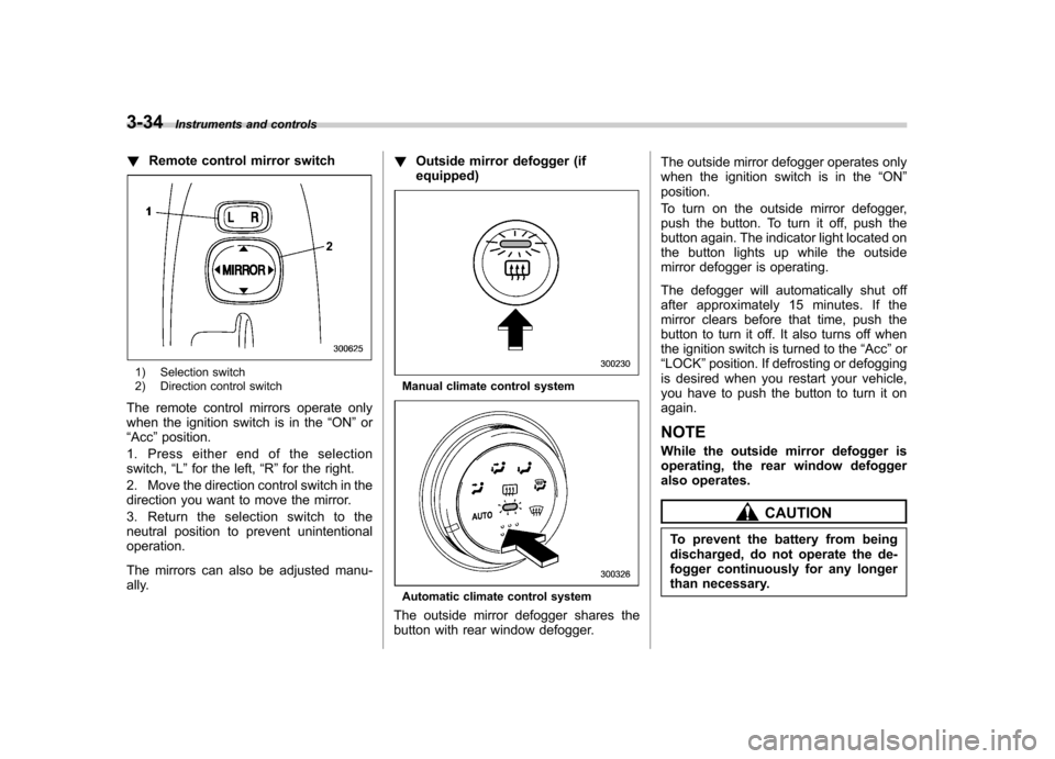
!Remote control mirror switch
1) Selection switch
2) Direction control switch
The remote control mirrors operate only
when the ignition switch is in the “ON ”or
“ Acc ”position.
1. Press either end of the selectionswitch, “L ” for the left, “R ”for the right.
2. Move the direction control switch in the
direction you want to move the mirror.
3. Return the selection switch to the
neutral position to prevent unintentionaloperation.
The mirrors can also be adjusted manu-
ally. !
Outside mirror defogger (ifequipped)Manual climate control system
Automatic climate control system
The outside mirror defogger shares the
button with rear window defogger. The outside mirror defogger operates only
when the ignition switch is in the
“ON ”
position.
To turn on the outside mirror defogger,
push the button. To turn it off, push the
button again. The indicator light located on
the button lights up while the outside
mirror defogger is operating.
The defogger will automatically shut off
after approximately 15 minutes. If the
mirror clears before that time, push the
button to turn it off. It also turns off when
the ignition switch is turned to the “Acc ”or
“ LOCK ”position. If defrosting or defogging
is desired when you restart your vehicle,
you have to push the button to turn it onagain. NOTE
While the outside mirror defogger is
operating, the rear window defogger
also operates.
CAUTION
To prevent the battery from being
discharged, do not operate the de-
fogger continuously for any longer
than necessary.
Page 335 of 364

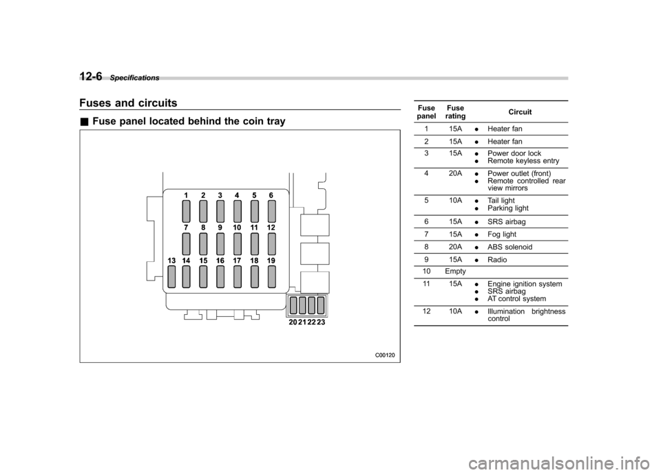
12-6Specifications
Fuses and circuits &Fuse panel located behind the coin trayFuse
panel Fuse
rating Circuit
1 15A .Heater fan
2 15A .Heater fan
3 15A .Power door lock
. Remote keyless entry
4 20A .Power outlet (front)
. Remote controlled rear
view mirrors
5 10A .Tail light
. Parking light
6 15A .SRS airbag
7 15A .Fog light
8 20A .ABS solenoid
9 15A .Radio
10 Empty
11 15A .Engine ignition system
. SRS airbag
. AT control system
12 10A .Illumination brightness
control
Page 355 of 364

14-2Index
A
ABS (Anti-lock Brake System) ..................................... 7-21
Warning light ................................................. 3-17, 7-22
Accessories ....................................................... 5-2, 11-44
Accessory power outlet ................................................. 6-6
Active head restraint ..................................................... 1-4
Air cleaner element ................................................... 11-15
Air conditioner ............................................................. 4-7
Air filtration system ..................................................... 4-12
Air flow selection .......................................................... 4-2
Alarm system ............................................................ 2-13
All-Wheel Drive warning light (AT vehicles) .................... 3-19
Aluminum wheels ...................................................... 11-35
Antenna system ........................................................... 5-2
Anti-lock Brake System (ABS) ..................................... 7-21
Arming the system ..................................................... 2-14
Armrest ....................................................................... 1-7
Ashtray ....................................................................... 6-8
AT OIL TEMPerature warning light ............................... 3-17
Audio set .................................................................... 5-3
Auto-dimming mirror/compass ...................................... 3-32
Automatic climate control system ................................... 4-8
Automatic transmission ............................................... 7-15
Capacities ............................................................. 12-4
Fluid .................................................................... 11-20
Selector lever ........................................................ 7-16
Temperature warning light (AT OIL TEMP) ................. 3-17
Automatic/Emergency Locking Retractor (A/ELR) ... ........ 1-11BBattery
.................................................................... 11-41
Jump starting .......................................................... 9-8
Replacement (Remote keyless entry system) .............. 2-7
Brake Booster ............................................................... 11-27
Fluid ................................................................... 11-25
Pad and lining ...................................................... 11-29
Parking ....................................................... 7-24, 11-30
Pedal .................................................................. 11-27
System .................................................................. 7-21
Brake pedal Free play ............................................................. 11-27
Reserve distance .................................................. 11-28
Brake system ............................................................. 7-21
Warning light .......................................................... 3-18
Braking ..................................................................... 7-20
Tips ...................................................................... 7-20
Breaking-in of new brake pads and linings ................... 11-29
Bulb Chart .................................................................... 12-9
Replacing ............................................................ 11-45
C Capacities ................................................................. 12-4
Cargo area Bars ...................................................................... 6-12
Cover .................................................................... 6-10
Light ...................................................................... 6-2
Tie-down hooks ...................................................... 6-11
Catalytic converter ....................................................... 8-3