2007 SUBARU IMPREZA heater
[x] Cancel search: heaterPage 5 of 364

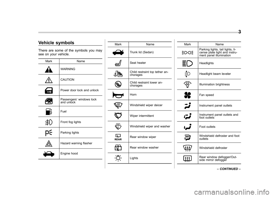
Vehicle symbols
There are some of the symbols you may
see on your vehicle.Mark Name
WARNING
CAUTION
Power door lock and unlock
Passengers ’windows lock
and unlock
Fuel
Front fog lights
Parking lights
Hazard warning flasher
Engine hood Mark Name
Trunk lid (Sedan)
Seat heater
Child restraint top tether an- chorages
Child restraint lower an- chorages
Horn
Windshield wiper deicer
Wiper intermittent
Windshield wiper and washer
Rear window wiper
Rear window washer
LightsMark Name
Parking lights, tail lights, li-
cense plate light and instru-
ment panel illumination
Headlights
Headlight beam leveler
Illumination brightness
Fan speed
Instrument panel outlets
Instrument panel outlets and
foot outlets
Foot outlets
Windshield defroster and foot outlets
Windshield defroster
Rear window defogger/Out-
side mirror defogger3
– CONTINUED –
Page 26 of 364

Front seats........................................................... 1-2
Fore and aft adjustment ....................................... 1-3
Reclining the seatback ........................................ 1-3
Seat cushion height adjustment (Driver ’s seat) ................................................... 1-4
Head restraint adjustment (if equipped) ................ 1-4
Active head restraint (if equipped) ....................... 1-4
Seat heater (if equipped) .................................... 1-5
Rear seats ............................................................ 1-6
Armrest (if equipped) ........................................... 1-7
Head restraint adjustment –Wagon ..................... 1-7
Folding down the rear seatback –Wagon. ............ 1-8
Seatbelts .............................................................. 1-9
Seatbelt safety tips .............................................. 1-9
Emergency Locking Retractor (ELR) ................... 1-11
Automatic/Emergency Locking Retractor (A/ELR) ............................................................ 1-11
Seatbelt warning light and chime ........................ 1-11
Fastening the seatbelt ........................................ 1-12
Seatbelt maintenance ......................................... 1-18
Seatbelt extender ............................................... 1-18 Front seatbelt pretensioners
............................. 1-19
System monitors ............................................... 1-20
System servicing ............................................... 1-21
Precautions against vehicle modification ............ 1-22
Child restraint systems ..................................... 1-22
Where to place a child restraint system .............. 1-23
Choosing a child restraint system ...................... 1-25
Installing child restraint systems with A/ELR seatbelt ........................................................... 1-25
Installing a booster seat ..................................... 1-28
Installation of child restraint systems by use of lower and tether anchorages (LATCH) .............. 1-29
Top tether anchorages ....................................... 1-32
*SRS airbag (Supplemental Restraint System airbag) ................................................ 1-35
Vehicle with driver ’s and front passenger ’s SRS
airbags and lap/shoulder restraints .................. 1-35
Subaru advanced frontal airbag system .............. 1-39
SRS side airbag ................................................. 1-50
SRS airbag system monitors .............................. 1-55
SRS airbag system servicing ... .......................... 1-56
Precautions against vehicle modification ............ 1-57
Seat, seatbelt and SRS airbags1
Page 30 of 364

tion on the seat.
. If your vehicle is involved in a
rear-end collision, have an
authorized SUBARU dealer in-
spect the active head restraints.
. The active head restraints may
not operate in the event the
vehicle experiences only a slight
impact in the rear.
. The active head restraints may be
damaged if they are pushed hard
from behind or subjected to
shock. As a result, they may not
function if the vehicle suffers a
rear impact. Seat heater (if equipped)
Driver
’s side
1) HI–Rapid heating
2) LO–Normal heating
Front passenger ’s side
1) HI–Rapid heating
2) LO–Normal heating
The seat heater operates when the igni-
tion switch is either in the “Acc ”or “ON ”
position.
To turn on the seat heater, push the “LO ”
or “HI ”position on the switch, as desired,
depending on the temperature. Selecting the “HI ”position will cause the seat to heat
up quicker.
The indicator located on the switch comes
on when the seat heater is in operation.
When the vehicle ’s interior is warmed
enough or before you leave the vehicle,
be sure to turn the switch off. Seat, seatbelt and SRS airbags
1-5
– CONTINUED –
Page 31 of 364

1-6Seat, seatbelt and SRS airbags
CAUTION
. There is a possibility that people
with delicate skin may suffer
slight burns even at low tempera-
tures if he/she uses the seat
heater for a long period of time.
When using the heater, always be
sure to warn the persons con-cerned.
. Do not put anything on the seat
which insulates against heat,
such as a blanket, cushion, or
similar items. This may cause the
seat heater to overheat.
NOTE
Use of the seat heater for a long period
of time while the engine is not running
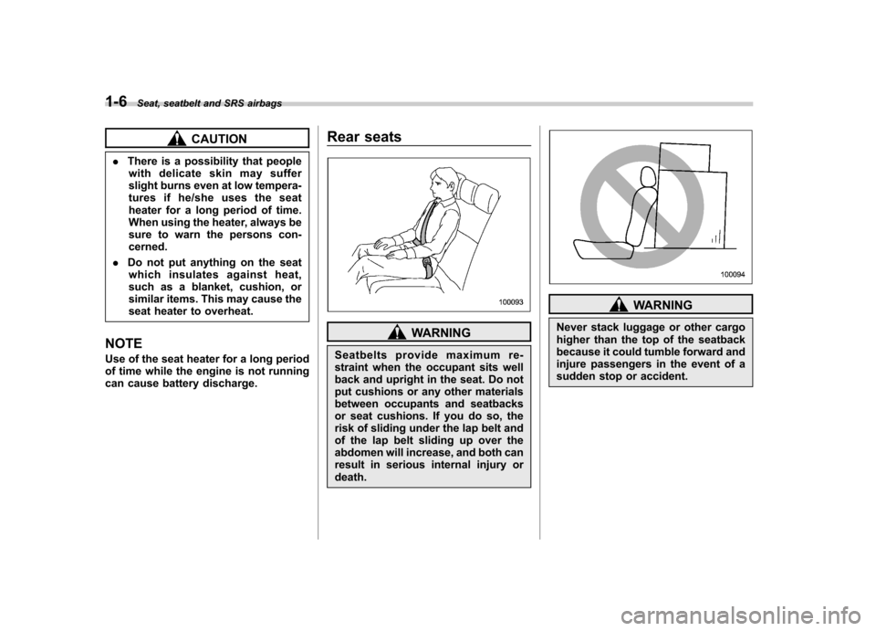
can cause battery discharge. Rear seats
WARNING
Seatbelts provide maximum re-
straint when the occupant sits well
back and upright in the seat. Do not
put cushions or any other materials
between occupants and seatbacks
or seat cushions. If you do so, the
risk of sliding under the lap belt and
of the lap belt sliding up over the
abdomen will increase, and both can
result in serious internal injury ordeath.
WARNING
Never stack luggage or other cargo
higher than the top of the seatback
because it could tumble forward and
injure passengers in the event of a
sudden stop or accident.
Page 142 of 364

cotton cloth or an applicator. !Compass calibration
1. For optimum calibration, switch off all
nonessential electrical accessories (rear
window defogger, heater/air conditioning
system, spotlight, etc.) and ensure all
doors are shut.
2. Drive to an open, level area away from
large metallic objects or structures and
make certain the ignition switch is in the“ ON ”position.
3. Press and hold the left button for 3
seconds then release, and the compass
will enter the calibration mode. “CAL ”and
direction will be displayed.
4. Drive slowly in a circle until “CAL ”
disappears from the display (approxi-
mately two or three circles). The compass
is now calibrated.
5. Further calibration may be necessary
should outside. Influences cause the
mirror to read inaccurately. You will know
that this has occurred if your compass
begins to read in only limited directions.
Should you encounter this situation, return
to step one of the above procedure and
recalibrate the mirror. !
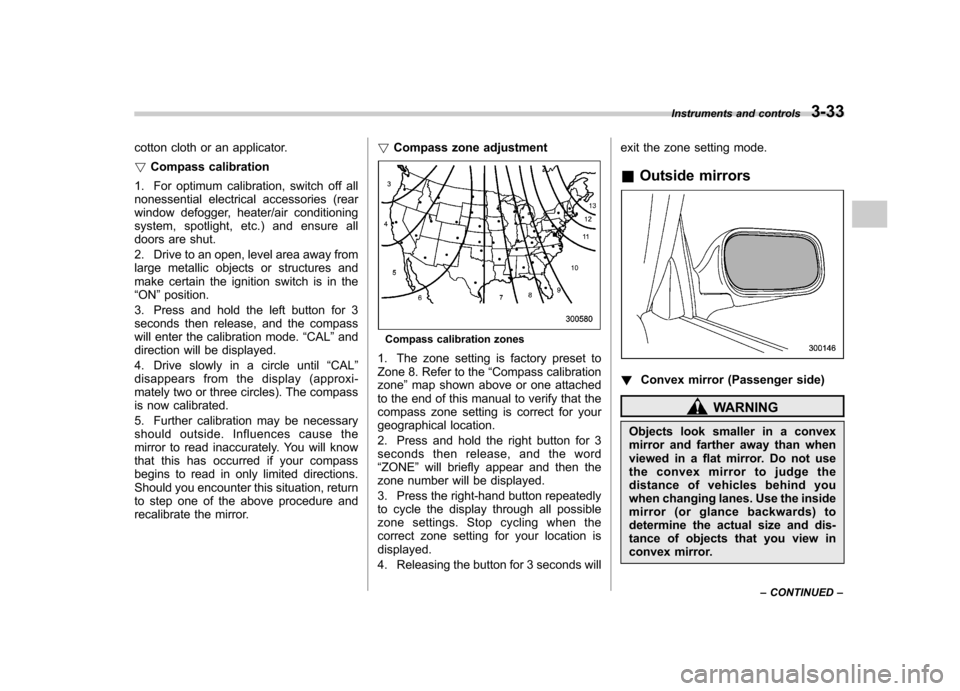
Compass zone adjustment
Compass calibration zones
1. The zone setting is factory preset to
Zone 8. Refer to the “Compass calibration
zone ”map shown above or one attached
to the end of this manual to verify that the
compass zone setting is correct for your
geographical location.
2. Press and hold the right button for 3
seconds then release, and the word“ ZONE ”will briefly appear and then the
zone number will be displayed.
3. Press the right-hand button repeatedly
to cycle the display through all possible
zone settings. Stop cycling when the
correct zone setting for your location isdisplayed.
4. Releasing the button for 3 seconds will exit the zone setting mode.
& Outside mirrors
! Convex mirror (Passenger side)
WARNING
Objects look smaller in a convex
mirror and farther away than when
viewed in a flat mirror. Do not use
the convex mirror to judge the
distance of vehicles behind you
when changing lanes. Use the inside
mirror (or glance backwards) to
determine the actual size and dis-
tance of objects that you view in
convex mirror. Instruments and controls
3-33
– CONTINUED –
Page 145 of 364

Ventilator.............................................................. 4-2
Air flow selection ................................................ 4-2
Center and side ventilators .................................. 4-3
Manual climate control system (if equipped) ..................................................... 4-3
Control panel ...................................................... 4-3
Heater operation ................................................. 4-5
Air conditioner operation (if equipped) ...................................................... 4-7
Automatic climate control system (if equipped) ..................................................... 4-8
Control panel ...................................................... 4-8
To use as full-automatic climate control system .............................................................. 4-8
To use as semi-automatic climate control system .............................................................. 4-8
Fan speed control dial ......................................... 4-9
Temperature control dial ...................................... 4-9
Air flow control dial ............................................. 4-9 Air inlet selection button
.................................... 4-10
Air conditioner button ........................................ 4-10
Temperature sensors ......................................... 4-11
Operating tips for heater and air conditioner ...................................................... 4-11
Cleaning ventilation grille ................................... 4-11
Efficient cooling after parking in direct sunlight ........................................................... 4-11
Lubrication oil circulation in the refrigerant circuit .............................................................. 4-12
Checking air conditioning system before summer season ............................................................ 4-12
Cooling and dehumidifying in high humidity and low temperature weather conditions ................. 4-12
Air conditioner compressor shut-off when engine is heavily loaded .............................................. 4-12
Refrigerant for your climate control system ... ..... 4-12
Air filtration system ........................................... 4-12
Replacing the air filter ........................................ 4-13Climate control
4
Page 149 of 364

&Heater operation
! Defrosting or defogging the wind- shield
To direct warm air to the windshield and
front door windows:
1. Set the air inlet selection lever to the “
”position.
2. Set the air flow control dial to the “
”
position.
3. Turn the temperature control dial all
the way to the right.
4. Set the fan speed control dial to the
highest speed.
If your vehicle is equipped with an air
conditioner, when the “
”or “”position
is selected, the air conditioner compressor
automatically operates regardless of the position of the air conditioner button to
defog the windshield quickly.
However, the air conditioner indicator light
does not come on at this time.
NOTE
Warm air also comes out from the right
and left air outlets. To stop warm air
flow from these outlets, turn the corre-
sponding knob clockwise. ! Heating and defrosting
To direct warm air toward the floor and the windshield:
1. Set the air inlet selection lever to the “
”position.
2. Set the air flow control dial to the “
”
position.
3. Set the temperature control dial to the most comfortable level.
4. Set the fan speed control dial to the
desired speed.
If your vehicle is equipped with an air
conditioner, when the
“
”or “”position
is selected, the air conditioner compressor
automatically operates regardless of the
position of the air conditioner button to
defog the windshield quickly.
However, the air conditioner indicator light
does not come on at this time.
NOTE
Warm air also comes out from the right
and left air outlets. To stop warm air
flow from these outlets, turn the corre-
sponding knob clockwise. Climate control
4-5
– CONTINUED –
Page 155 of 364

other factors. Pressing the button cancels the“AUTO ”mode. SUBARU recommends
using the AUTO position.
NOTE
The air conditioner ’s compressor does
not operate with an outside tempera-
ture of 32 8F(0 8C) or lower.
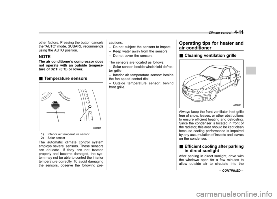
& Temperature sensors
1) Interior air temperature sensor
2) Solar sensor
The automatic climate control system
employs several sensors. These sensors
are delicate. If they are not treated
properly and become damaged, the sys-
tem may not be able to control the interior
temperature correctly. To avoid damaging
the sensors, observe the following pre- cautions: –
Do not subject the sensors to impact.
– Keep water away from the sensors.
– Do not cover the sensors.
The sensors are located as follows:– Solar sensor: beside windshield defros-
ter grille– Interior air temperature sensor: beside
the fan speed control dial– Outside temperature sensor: behind
front grille. Operating tips for heater and
air conditioner &
Cleaning ventilation grille
Always keep the front ventilator inlet grille
free of snow, leaves, or other obstructions
to ensure efficient heating and defrosting.
Since the condenser is located in front of
the radiator, this area should be kept clean
because cooling performance is impaired
by any accumulation of insects and leaves
on the condenser. &Efficient cooling after parking
in direct sunlight
After parking in direct sunlight, drive with
the windows open for a few minutes to
allow outside air to circulate into the Climate control
4-11
– CONTINUED –