2007 SUBARU IMPREZA warning
[x] Cancel search: warningPage 107 of 364

2-24Keys and doors
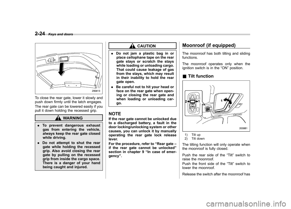
To close the rear gate, lower it slowly and
push down firmly until the latch engages.
The rear gate can be lowered easily if you
pull it down holding the recessed grip.
WARNING
. To prevent dangerous exhaust
gas from entering the vehicle,
always keep the rear gate closed
while driving.
. Do not attempt to shut the rear
gate while holding the recessed
grip. Also avoid closing the rear
gate by pulling on the recessed
grip from inside the cargo space.
There is a danger of your hand
being caught and injured.
CAUTION
. Do not jam a plastic bag in or
place cellophane tape on the rear
gate stays or scratch the stays
while loading or unloading cargo.
That could cause leakage of gas
from the stays, which may result
in their inability to hold the rear
gate open.
. Be careful not to hit your head or
face on the rear gate when open-
ing or closing the rear gate and
when loading or unloading car-go.
NOTE
If the rear gate cannot be unlocked due
to a discharged battery, a fault in the
door locking/unlocking system or other
causes, you can unlock it by manually
operating the rear gate lock release
lever.
For the procedure, refer to “Rear gate –
if the rear gate cannot be unlocked ”
section in chapter 9 “In case of emer-
gency ”. Moonroof (if equipped)
The moonroof has both tilting and sliding functions.
The moonroof operates only when the
ignition switch is in the
“ON ”position.
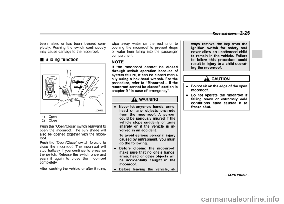
& Tilt function
1) Tilt up
2) Tilt down
The tilting function will only operate when
the moonroof is fully closed.
Push the rear side of the “Tilt ”switch to
raise the moonroof.
Push the front side of the “Tilt ”switch to
lower the moonroof.
Release the switch after the moonroof has
Page 108 of 364

been raised or has been lowered com-
pletely. Pushing the switch continuously
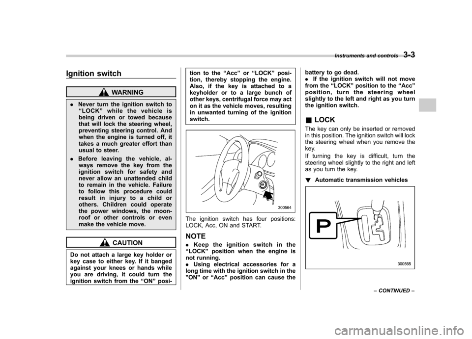
may cause damage to the moonroof. &Sliding function
1) Open
2) Close
Push the “Open/Close ”switch rearward to
open the moonroof. The sun shade will
also be opened together with the moon-roof.
Push the “Open/Close ”switch forward to
close the moonroof. The moonroof will
stop halfway if you continue to press on
the switch. Release the switch once and
push it again to close the moonroof
completely.
After washing the vehicle or after it rains, wipe away water on the roof prior to
opening the moonroof to prevent drops
of water from falling into the passengercompartment.
NOTE
If the moonroof cannot be closed
through switch operation because of
system failure, it can be closed manu-
ally using a hex-head wrench. For the
procedure, refer to “Moonroof –if the
moonroof cannot be closed ”section in
chapter 9 “In case of emergency ”.
WARNING
. Never let anyone ’s hands, arms,
head or any objects protrude
from the moonroof. A person
could be seriously injured if the
vehicle stops suddenly or turns
sharply or if the vehicle is in-
volved in an accident.
To avoid serious personal injury
caused by entrapment, you must
do the following.
. Before closing the moonroof,
make sure that no one ’s hands,
arms, head or other objects will
be accidentally caught in themoonroof.
. Before leaving the vehicle, al- ways remove the key from the
ignition switch for safety and
never allow an unattended child
to remain in the vehicle. Failure
to follow this procedure could
result in injury to a child operat-
ing the moonroof.
CAUTION
. Do not sit on the edge of the open
moonroof.
. Do not operate the moonroof if
falling snow or extremely cold
conditions have caused it to
freeze shut. Keys and doors
2-25
– CONTINUED –
Page 110 of 364

Ignition switch..................................................... 3-3
LOCK .................................................................. 3-3
Acc..................................................................... 3-4
ON...................................................................... 3-4
START ................................................................ 3-4
Key reminder chime ............................................ 3-5
Ignition switch light ............................................. 3-5
Key interlock release (AT vehicles only) ... ............ 3-5
Hazard warning flasher ....................................... 3-6
Meters and gauges (WRX-STI) ........................... 3-6
Combination meter illumination ........................... 3-6
Canceling sequential illumination of the combination meter ............................................ 3-6
Speedometer ....................................................... 3-7
Odometer/Trip meter ............................................ 3-7
Tachometer ......................................................... 3-7
Fuel gauge .......................................................... 3-8
Temperature gauge ............................................. 3-8
Outside temperature indicator ............................. 3-9
REV indicator light and buzzer (WRX-STI) ........ 3-9
Setting the alarm-level engine speed ................... 3-10
Deactivating the REV alarm system ..................... 3-11
Meters and gauges (Except WRX-STI) .............. 3-11
Speedometer ...................................................... 3-11
Odometer/Trip meter ........................................... 3-11
Tachometer ........................................................ 3-12
Fuel gauge ......................................................... 3-12
Temperature gauge ............................................ 3-13
Outside temperature indicator ............................ 3-13
Warning and indicator lights ............................. 3-14
Seatbelt warning light and chime ........................ 3-14SRS airbag system warning light
........................ 3-14
Front passenger ’s frontal airbag ON and OFF
indicators ........................................................ 3-15
CHECK ENGINE warning light/Malfunction indicator lamp ................................................. 3-16
Charge warning light .......................................... 3-16
Oil pressure warning light .................................. 3-16
AT OIL TEMPerature warning light (AT vehicles) .................................................... 3-17
Rear differential oil temperature warning light (WRX-STI) ........................................................ 3-17
ABS warning light .............................................. 3-17
Brake system warning light ................................ 3-18
Door open warning light .................................... 3-19
All-Wheel Drive warning light (AWD AT vehicles –
if equipped) ..................................................... 3-19
Intercooler water spray warning light (WRX-STI) ........................................................ 3-19
Selector lever position indicator (AT vehicles) .................................................... 3-20
Turn signal indicator lights ................................. 3-20
High beam indicator light ................................... 3-20
Cruise control indicator light .............................. 3-20
Cruise control set indicator light ........................ 3-20
Driver ’s control center differential auto indicator
light (WRX-STI) ................................................ 3-20
Driver ’s control center differential indicator and
warning lights (WRX-STI) ................................. 3-21
Lights indicator light (WRX-STI) ......................... 3-21
REV indicator light (WRX-STI) .. .......................... 3-21
Clock .................................................................. 3-22Instruments and controls
3
Page 112 of 364

Ignition switch
WARNING
. Never turn the ignition switch to
“ LOCK ”while the vehicle is
being driven or towed because
that will lock the steering wheel,
preventing steering control. And
when the engine is turned off, it
takes a much greater effort than
usual to steer.
. Before leaving the vehicle, al-
ways remove the key from the
ignition switch for safety and
never allow an unattended child
to remain in the vehicle. Failure
to follow this procedure could
result in injury to a child or
others. Children could operate
the power windows, the moon-
roof or other controls or even
make the vehicle move.
CAUTION
Do not attach a large key holder or
key case to either key. If it banged
against your knees or hands while
you are driving, it could turn the
ignition switch from the “ON ”posi- tion to the
“Acc ”or “LOCK ”posi-
tion, thereby stopping the engine.
Also, if the key is attached to a
keyholder or to a large bunch of
other keys, centrifugal force may act
on it as the vehicle moves, resulting
in unwanted turning of the ignitionswitch.
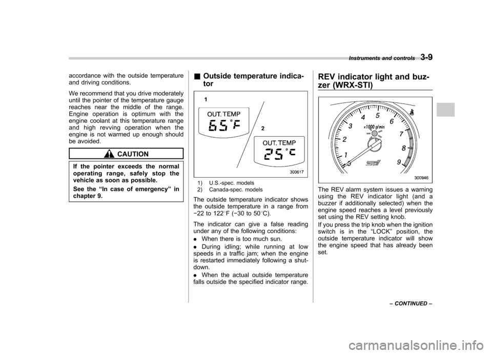
The ignition switch has four positions:
LOCK, Acc, ON and START. NOTE . Keep the ignition switch in the
“ LOCK ”position when the engine is
not running. . Using electrical accessories for a
long time with the ignition switch in the
"ON" or “Acc ”position can cause the battery to go dead..
If the ignition switch will not move
from the “LOCK ”position to the “Acc ”
position, turn the steering wheel
slightly to the left and right as you turn
the ignition switch. & LOCK
The key can only be inserted or removed
in this position. The ignition switch will lock
the steering wheel when you remove the
key.
If turning the key is difficult, turn the
steering wheel slightly to the right and left
as you turn the key. ! Automatic transmission vehicles
Instruments and controls 3-3
– CONTINUED –
Page 115 of 364

3-6Instruments and controls
Hazard warning flasher
The hazard warning flasher is used to
warn other drivers when you have to park
your vehicle under emergency conditions.
The hazard warning flasher works with the
ignition switch in any position.
To turn on the hazard warning flasher,
push the hazard warning button on the
instrument panel. To turn off the flasher,
push the button again. NOTE
When the hazard warning flasher is on,
the turn signals do not work. Meters and gauges (WRX- STI) NOTE
Liquid-crystal displays are used in
some of the meters and gauges in the
combination meter. You will find their
indications hard to see if you wear
polarized glasses. &
Combination meter illumina- tion
When the ignition switch is turned to the “ ON ”position, the various parts of the
combination meter are illuminated in the
following sequence:
1. Meter needles and gauge needles
light up.
2. Meter needles and gauge needles
each show MAX position.
3. Meter needles and gauge needles
each show MIN position, and REV indi-
cator flashes.
4. Dials and indicators in meters and
gauges light up. 5. “STI ”mark lights up.
6. Regular illumination (for driving) be- gins. &
Canceling sequential illumi-
nation of the combination meter
With the ignition switch in the “ON ”
position, it is possible to cancel sequential
illumination of the combination meter.
Press the trip knob while turning the REV
setting knob clockwise or counterclock-
wise. The buzzer will sound briefly, and
the outside temperature indicator willshow “ON ”or “– –” .
ON : sequential illumination –– : sequential illumination canceled
The setting toggles between “ON ”and “–
–” each time the trip knob is pressed.
Return the REV setting knob to its original
position to complete the setting process.
The buzzer will sound briefly. A few
seconds later, the outside temperature
indicator will return to showing the outsidetemperature. NOTE
It is not possible to cancel sequential
illumination of the combination meter
while sequential illumination is actually
taking place. Cancel sequential illumi-
nation when regular illumination (for
driving) has begun.
Page 117 of 364

3-8Instruments and controls
&Fuel gauge
1) Low fuel warning light
The fuel gauge shows the approximate
amount of fuel remaining in the tank.
When the ignition switch is in the “LOCK ”
or “Acc ”position, the fuel gauge shows “E ”
even if the fuel tank contains fuel.
The gauge may move slightly during
braking, turning or acceleration due to fuel
level movement in the tank. NOTE
You will see the
“”sign in the fuel
gauge meter.
This indicates that the fuel filler door
(lid) is located on the right side of thevehicle. ! Low fuel warning light
The low fuel warning light comes on when
the tank is nearly empty [Approximately
2.3 US gal (9.0 liters, 1.9 Imp gal)].
It only operates when the ignition switch is
in the “ON ”position.
NOTE
This light does not go out unless the
tank is replenished up to an internal fuel quantity of approximately 4.0 US
gal (15 liters, 3.3 Imp gal).
CAUTION
Promptly put fuel in the tank when-
ever the low fuel warning light
comes on. Engine misfires as a
result of an empty tank could cause
damage to the engine.
& Temperature gauge
1) Normal operating range
The temperature gauge shows engine
coolant temperature when the ignition
switch is in the “ON ”position.
The coolant temperature will vary in
Page 118 of 364

accordance with the outside temperature
and driving conditions.
We recommend that you drive moderately
until the pointer of the temperature gauge
reaches near the middle of the range.
Engine operation is optimum with the
engine coolant at this temperature range
and high revving operation when the
engine is not warmed up enough should
be avoided.
CAUTION
If the pointer exceeds the normal
operating range, safely stop the
vehicle as soon as possible.
See the “In case of emergency ”in
chapter 9. &
Outside temperature indica- tor
1) U.S.-spec. models
2) Canada-spec. models
The outside temperature indicator shows
the outside temperature in a range from� 22 to 122 8F( �30 to 50 8C).
The indicator can give a false reading
under any of the following conditions: . When there is too much sun.
. During idling; while running at low
speeds in a traffic jam; when the engine
is restarted immediately following a shut- down. . When the actual outside temperature
falls outside the specified indicator range. REV indicator light and buz-
zer (WRX-STI)The REV alarm system issues a warning
using the REV indicator light (and a
buzzer if additionally selected) when the
engine speed reaches a level previously
set using the REV setting knob.
If you press the trip knob when the ignition
switch is in the
“LOCK ”position, the
outside temperature indicator will show
the engine speed that has already beenset. Instruments and controls
3-9
– CONTINUED –
Page 119 of 364

3-10Instruments and controls
NOTE
Even if the REV alarm system is not set,
the REV indicator light will come on
whenever the engine speed enters thetachometer ’s red zone.
& Setting the alarm-level en-
gine speed
1. Turn the REV setting knob clockwise
or counterclockwise, then release it and
let it return to its initial position. The buzzer
will sound. The REV alarm system is now
ready to be set.
2. Turn the REV setting knob to select
the desired alarm-level engine speed.
At this time, the outside temperature
indicator will show the engine-speed setting. .
Counterclockwise ( �): Speed setting
changes downward by 100 rpm. . Clockwise (+): Speed setting
changes upward by 100 rpm.
The speed setting will stop changing if
it reaches 0 rpm or the maximum
engine speed.
The alarm-level engine speed can be set
(in 100 rpm steps) within the range from
2,000 rpm to 7,000 rpm.
The indicator shows the setting as follows:
Speed (rpm) Indication 00 0
2,000 20
2,100 21 ––
7,000 70
Approximately 3 seconds after you stop
turning the knob, the REV alarm system
will automatically enter its next setting
mode (step 3 below), in which you can
activate or deactivate the buzzer.
3. Activate or deactivate the buzzer as
desired using the REV setting knob. .Turn the knob clockwise (+) to
activate the buzzer. The indicator willshow “ON ”, and the buzzer will sound three times. With the buzzer activated,
engine-speed warnings are given by
both the REV indicator light and the
buzzer. .
Turn the knob counterclockwise ( �)
to deactivate the buzzer. The indicator
will show “– –”, and the buzzer will not
sound. With the buzzer deactivated,
engine-speed warnings are given only
by the REV indicator light.
Approximately 3 seconds after you stop
turning the knob, the buzzer will sound
once to indicate the end of the setting
procedure. The indicator will return to
showing the outside temperature.
Also, the tachometer needle will return to approximately “0 ”.
NOTE . The REV alarm system does not
operate while settings are being en- tered.. The speed-setting mode terminates
if 0 rpm is selected.. The speed-setting mode is canceled
if the ignition switch is turned to OFF or
the vehicle starts moving before the
setting procedure is finished.. Speed setting is impossible when
the vehicle is moving.. The set engine speed may differ