2007 SUBARU IMPREZA ECO mode
[x] Cancel search: ECO modePage 116 of 364

&Speedometer
The speedometer shows the vehicle speed. & Odometer/Trip meter
1) Trip meter
2) Odometer
This meter displays the odometer and two
trip meters when the ignition switch is inthe “LOCK ”, “Acc ”or “ON ”position.
If you press the trip knob when the ignition
switch is in the “LOCK ”position, the
odometer/trip meter will light up. It is
possible to switch between the A trip
meter and B trip meter indications while
the odometer/trip meter is lit up. If you do
not press the trip knob within 10 seconds
of illumination of the odometer/trip meter, the odometer/trip meter will go off. !
Odometer
The odometer shows the total distance
that the vehicle has been driven. ! Double trip meter
The trip meter shows the distance that the
vehicle has been driven since you last set
it to zero.
To change the mode indication, briefly
push the knob.
Each press of the knob changes the
function alternately.
To set the trip meter to zero, select the A
trip or B trip meter by pushing the knob
and keep the knob pushed for more than 2 seconds.
CAUTION
To ensure safety, do not attempt to
change the function of the indicator
during driving, as an accident couldresult.
NOTE
If the connection between the combina-
tion meter and battery is broken for any
reason such as vehicle maintenance or
fuse replacement, the data recorded on
the trip meter will be lost. & Tachometer
The tachometer shows the engine speed
in thousands of revolutions per minute.
CAUTION
Do not operate the engine with the
pointer of the tachometer in the red
zone. In this range, fuel injection will
be cut by the engine control module
to protect the engine from overrev-
ving. The engine will resume run-
ning normally after the engine speed
is reduced below the red zone. Instruments and controls
3-7
– CONTINUED –
Page 118 of 364

accordance with the outside temperature
and driving conditions.
We recommend that you drive moderately
until the pointer of the temperature gauge
reaches near the middle of the range.
Engine operation is optimum with the
engine coolant at this temperature range
and high revving operation when the
engine is not warmed up enough should
be avoided.
CAUTION
If the pointer exceeds the normal
operating range, safely stop the
vehicle as soon as possible.
See the “In case of emergency ”in
chapter 9. &
Outside temperature indica- tor
1) U.S.-spec. models
2) Canada-spec. models
The outside temperature indicator shows
the outside temperature in a range from� 22 to 122 8F( �30 to 50 8C).
The indicator can give a false reading
under any of the following conditions: . When there is too much sun.
. During idling; while running at low
speeds in a traffic jam; when the engine
is restarted immediately following a shut- down. . When the actual outside temperature
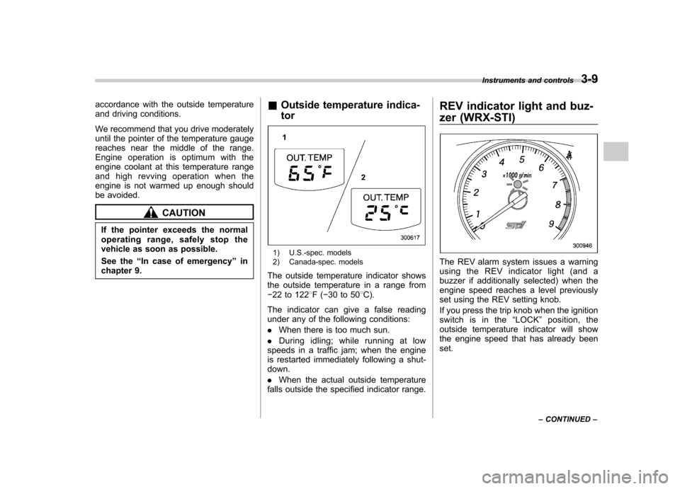
falls outside the specified indicator range. REV indicator light and buz-
zer (WRX-STI)The REV alarm system issues a warning
using the REV indicator light (and a
buzzer if additionally selected) when the
engine speed reaches a level previously
set using the REV setting knob.
If you press the trip knob when the ignition
switch is in the
“LOCK ”position, the
outside temperature indicator will show
the engine speed that has already beenset. Instruments and controls
3-9
– CONTINUED –
Page 119 of 364

3-10Instruments and controls
NOTE
Even if the REV alarm system is not set,
the REV indicator light will come on
whenever the engine speed enters thetachometer ’s red zone.
& Setting the alarm-level en-
gine speed
1. Turn the REV setting knob clockwise
or counterclockwise, then release it and
let it return to its initial position. The buzzer
will sound. The REV alarm system is now
ready to be set.
2. Turn the REV setting knob to select
the desired alarm-level engine speed.
At this time, the outside temperature
indicator will show the engine-speed setting. .
Counterclockwise ( �): Speed setting
changes downward by 100 rpm. . Clockwise (+): Speed setting
changes upward by 100 rpm.
The speed setting will stop changing if
it reaches 0 rpm or the maximum
engine speed.
The alarm-level engine speed can be set
(in 100 rpm steps) within the range from
2,000 rpm to 7,000 rpm.
The indicator shows the setting as follows:
Speed (rpm) Indication 00 0
2,000 20
2,100 21 ––
7,000 70
Approximately 3 seconds after you stop
turning the knob, the REV alarm system
will automatically enter its next setting
mode (step 3 below), in which you can
activate or deactivate the buzzer.
3. Activate or deactivate the buzzer as
desired using the REV setting knob. .Turn the knob clockwise (+) to
activate the buzzer. The indicator willshow “ON ”, and the buzzer will sound three times. With the buzzer activated,
engine-speed warnings are given by
both the REV indicator light and the
buzzer. .
Turn the knob counterclockwise ( �)
to deactivate the buzzer. The indicator
will show “– –”, and the buzzer will not
sound. With the buzzer deactivated,
engine-speed warnings are given only
by the REV indicator light.
Approximately 3 seconds after you stop
turning the knob, the buzzer will sound
once to indicate the end of the setting
procedure. The indicator will return to
showing the outside temperature.
Also, the tachometer needle will return to approximately “0 ”.
NOTE . The REV alarm system does not
operate while settings are being en- tered.. The speed-setting mode terminates
if 0 rpm is selected.. The speed-setting mode is canceled
if the ignition switch is turned to OFF or
the vehicle starts moving before the
setting procedure is finished.. Speed setting is impossible when
the vehicle is moving.. The set engine speed may differ
Page 122 of 364

fuel quantity of approximately 4.0 US
gal (15 liters, 3.3 Imp gal).
CAUTION
(Turbo model only)
Promptly put fuel in the tank when-
ever the low fuel warning light
comes on. Engine misfires as a
result of an empty tank could cause
damage to the engine.
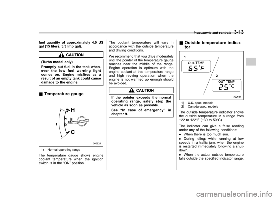
& Temperature gauge
1) Normal operating range
The temperature gauge shows engine
coolant temperature when the ignition
switch is in the “ON ”position. The coolant temperature will vary in
accordance with the outside temperature
and driving conditions.
We recommend that you drive moderately
until the pointer of the temperature gauge
reaches near the middle of the range.
Engine operation is optimum with the
engine coolant at this temperature range
and high revving operation when the
engine is not warmed up enough should
be avoided.
CAUTION
If the pointer exceeds the normal
operating range, safely stop the
vehicle as soon as possible. See “In case of emergency ”in
chapter 9. &
Outside temperature indica- tor
1) U.S.-spec. models
2) Canada-spec. models
The outside temperature indicator shows
the outside temperature in a range from� 22 to 122 8F( �30 to 50 8C).
The indicator can give a false reading
under any of the following conditions: . When there is too much sun.
. During idling; while running at low
speeds in a traffic jam; when the engine
is restarted immediately following a shut- down. . When the actual outside temperature
falls outside the specified indicator range. Instruments and controls
3-13
Page 129 of 364

3-20Instruments and controls
& Selector lever position indi-
cator (AT vehicles)
This indicator shows the position of the
selector lever. & Turn signal indicator lights
These lights show the operation of the turn
signal or lane change signal.
If the indicator lights do not blink or blink
rapidly, the turn signal bulb may be burned
out. Replace the bulb as soon as possible.
Refer to the “Replacing bulbs ”section in
chapter 11. &
High beam indicator light
This light shows that the headlights are in
the high beam mode.
This indicator light also comes on when
the headlight flasher is operated. &Cruise control indica-
tor light
The cruise control indicator light comes on
when the ignition switch is turned to the“ON ”position and goes out after approxi-
mately 3 seconds.
This light comes on when the “CRUISE ”
main switch is pressed.
If you move the cruise control lever or
press the main switch button while turning
the ignition switch “ON ”, the cruise control
function is deactivated and the “CRUISE ”
indicator light flashes. To reactivate the
cruise control function, turn the ignition
switch back to the “Acc ”or “LOCK ”
position, and then turn it again to the“ ON ”position.
& Cruise control set in-
dicator light
The cruise control set indicator light
comes on when the ignition switch is
turned to the “ON ”position and goes out after approximately 3 seconds.
This light comes on when vehicle speed
has been set.
& Driver ’s control center
differential auto indica-
tor light (WRX-STI)
This light functions while the ignition
switch is “ON ”. When on, it indicates that
the driver ’s control center differential is set
to AUTO mode. It goes off when thedriver ’s control center differential ’s manual
mode switch is pressed. For details, refer
to Chapter 7, “Driver ’s Control Center
Differential (DCCD) (WRX-STI) ”.
Page 142 of 364

cotton cloth or an applicator. !Compass calibration
1. For optimum calibration, switch off all
nonessential electrical accessories (rear
window defogger, heater/air conditioning
system, spotlight, etc.) and ensure all
doors are shut.
2. Drive to an open, level area away from
large metallic objects or structures and
make certain the ignition switch is in the“ ON ”position.
3. Press and hold the left button for 3
seconds then release, and the compass
will enter the calibration mode. “CAL ”and
direction will be displayed.
4. Drive slowly in a circle until “CAL ”
disappears from the display (approxi-
mately two or three circles). The compass
is now calibrated.
5. Further calibration may be necessary
should outside. Influences cause the
mirror to read inaccurately. You will know
that this has occurred if your compass
begins to read in only limited directions.
Should you encounter this situation, return
to step one of the above procedure and
recalibrate the mirror. !
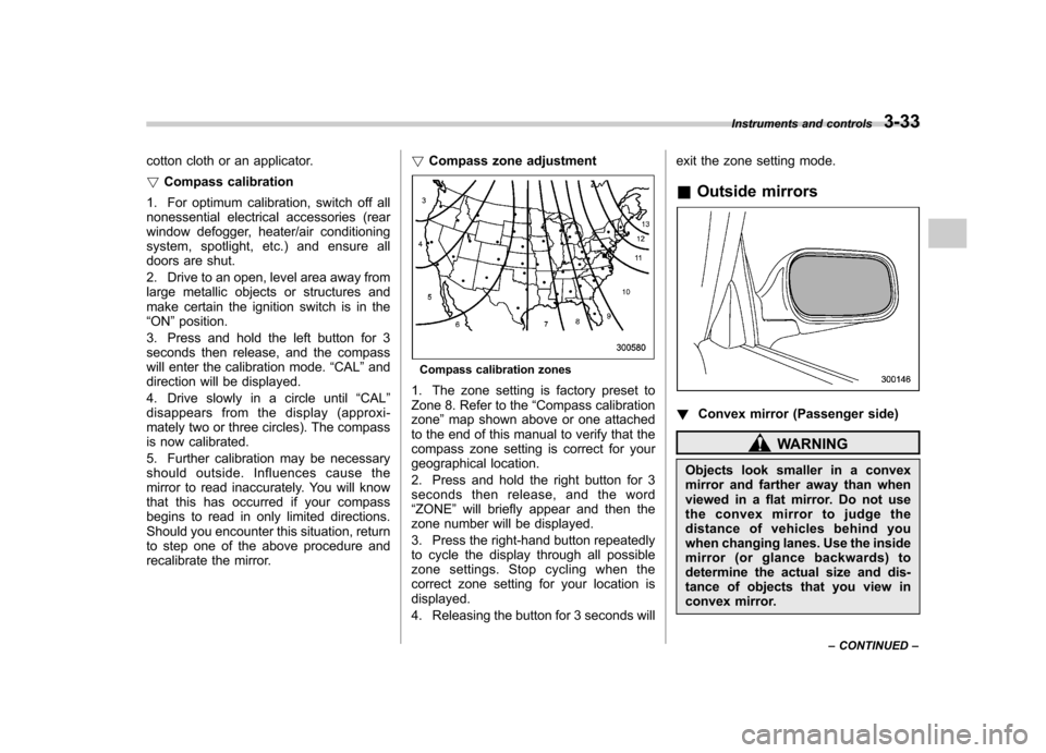
Compass zone adjustment
Compass calibration zones
1. The zone setting is factory preset to
Zone 8. Refer to the “Compass calibration
zone ”map shown above or one attached
to the end of this manual to verify that the
compass zone setting is correct for your
geographical location.
2. Press and hold the right button for 3
seconds then release, and the word“ ZONE ”will briefly appear and then the
zone number will be displayed.
3. Press the right-hand button repeatedly
to cycle the display through all possible
zone settings. Stop cycling when the
correct zone setting for your location isdisplayed.
4. Releasing the button for 3 seconds will exit the zone setting mode.
& Outside mirrors
! Convex mirror (Passenger side)
WARNING
Objects look smaller in a convex
mirror and farther away than when
viewed in a flat mirror. Do not use
the convex mirror to judge the
distance of vehicles behind you
when changing lanes. Use the inside
mirror (or glance backwards) to
determine the actual size and dis-
tance of objects that you view in
convex mirror. Instruments and controls
3-33
– CONTINUED –
Page 152 of 364

4-8Climate control
Automatic climate control
system (if equipped)
Although this climate control system can
be used as a full-automatic climate control
system, it can also, if desired, be used as
a semi-automatic climate control system.
When it is used as a full-automatic climate
control system, the outlet air temperature,
fan speed, air flow distribution, air inlet
control, and air conditioner compressor
operation are all automatically controlled
to maintain a constant, comfortable tem-
perature inside the vehicle. NOTE .Operate the automatic climate con-
trol system when the engine is running. . When the engine coolant is cold, the
blower does not run.. In the “AUTO ”mode, when the air
temperature in the passenger compart-
ment is sufficiently cool, the air condi-
tioner compressor does not operate.
For efficient defogging or dehumidify-
ing in cold weather, press the “A/C ”
button to operate the air conditioner
compressor.. Even when cooling is not necessary,
setting the temperature much lower
than the current outlet air temperature
turns on the air conditioner compres- sor automatically and the
“A/C ”indi-
cator light on the control panel comeson. & Control panel
1) Air flow control dial
2) Fan speed control dial
3) Temperature control dial
4) Air conditioner button
5) Air inlet selection button
6) Rear window defogger button (Refer to
the“Rear window defogger button ”sec-
tion in chapter 3.)
& To use as full-automatic cli-
mate control system
Place the temperature control dial in the
position for your desired temperature, then
set the other dials and buttons as de- scribed in the following. The system
’s
functions will then switch to AUTO mode
and be controlled automatically. . Air flow control dial: AUTO position
. Fan speed control dial: AUTO position
. Air inlet selection button: Press for at
least 1 second. (Indicator will flash twice.). Air conditioner button: Press for at least
1 second. (Indicator will flash twice.)
& To use as semi-automatic
climate control system
Each function can be individually set to
AUTO mode independently of the others.
Any function set to AUTO mode is con-
trolled automatically. Any function not set
to AUTO mode can be manually adjusted
as desired.
The temperature can be set within a range
of 65 to 85 8F (20 to 30 8C).
Page 153 of 364

&Fan speed control dial
The fan operates only with the ignition
switch in the ON position. The fan speed
control dial is used to select the AUTO
(automatic control) mode or to select the
desired fan speed. The dial ’s positions
and their functions are as follows: OFF: The fan does not operate.
AUTO: The fan speed is adjusted auto-
maticallyinaccordancewiththeair
temperature inside and outside the pas-
senger compartment, the intensity of sun-
light, and other factors. SUBARU recom-
mends using the AUTO position.
Other positions: The fan speed can be
adjusted in 25 steps. NOTE
With the fan speed control dial in the
AUTO position and the air flow control
dial in the
“
”, “”,or “”position,
the fan does not operate during engine
warm-up until the engine coolant tem-
perature exceeds approx. 122 8F (50 8C).
& Temperature control dial
This dial is used to set the desired interior
temperature. With the dial set to your
desired temperature, the system automa-
tically adjusts the temperature of air
supplied from the outlets such that the
desired temperature is achieved andmaintained.
If the dial is turned fully counterclockwise,
the system gives maximum cooling per- formance. If the dial is turned fully clock-
wise, the system gives maximum heatingperformance. &
Air flow control dial
This dial has the following six positions.
The outlets from which air is supplied in
each position are as follows: AUTO: The air flow control is adjusted
automatically in accordance with the air
temperature inside and outside the pas-
senger compartment, the intensity of sun-
light, and other factors. SUBARU recom-
mends using the AUTO position.
: Instrument panel outlets
: Instrument panel outlets and foot
outlets
: Foot outlets and windshield defroster Climate control
4-9
– CONTINUED –