Page 93 of 465
0-7
SPECIAL SERVICE TOOLS
RODIUS 2006.09
0000-00
Name and Part Number Application
Y99220122B
Piston protrusion measuring jig
Y99220172B
Piston insertion jig
Page 94 of 465
0-8
RODIUS 2006.09
0000-00
SPECIAL SERVICE TOOLS
Name and Part Number Application
Y99220112B
Intake manifold guide pinInstallation of intake manifold
2. ENGINE INTAKE SYSTEM
Page 95 of 465
0-9
SPECIAL SERVICE TOOLS
RODIUS 2006.09
0000-00
Name and Part Number Application
103 589 02 09 00
Engine filter cap
3. ENGINE LUBRICATION SYSTEM
1) SPECIAL TOOLS AND EQUIPMENT
Page 96 of 465
0-10
RODIUS 2006.09
0000-00
SPECIAL SERVICE TOOLS
4. ENGINE COOLING
SYSTEM
1) SPECIAL TOOLS AND EQUIPMENT
Page 169 of 465
01-4
RODIUS 2006.09
0000-00
FUSE AND RELAY
Fuse and Relay in Instrument Panel
▶
The fuse box is underneath the dash board on the driver's side. You can find the function,
location and capacity for fuses from the back plate of the fuse box cover. If any electrical device
doesn't operate, check for an open fuse. If any fuse is blown, replace it with a new fuse.
If a new fuse also opens, have the electrical system checked and repaired by Ssangyong
Dealer or Ssangyong Authorized Service Operation.
Page 222 of 465
0-10
RODIUS 2006.09
8010-10
CLUSTER
3) Fuel Level Gauge
The fuel level gauge displays the resistance value of the float on the fuel sender in the fuel tank
through a pointer. Note that this vehicle doesn’t have a service hole for checking the fuel
sender connector in the fuel tank.
The fuel sender and its connector can be checked and replaced only when the fuel tank is
removed. The power supply and resistance value should be measured at the connector in front
of the fuel sender (refer to wiring diagram).
When the power supply and output resistance are normal, the float operation by fuel level may
be defective; if so, replace the fuel sender.
Tolerance and resistance value by indicating angle
This table shows the tolerance and resistance value changes by fuel level in normal conditions.
Therefore, the differences that can be occurred by the road conditions and fuel fluctuations are
ignored.
Page 349 of 465

0-10
RODIUS 2006.09
4892-01
ABS SYSTEM
3. ON-VEHICLE SERVICE
(1) Electronic system service precautions
Take care to avoid electronic brake control module (HECU) circuit overloading. In testing for
opens or shorts, do not ground or apply voltage to any circuit unless instructed to do so by the
diagnostic procedure. Test circuits only with a high-impedance multi-meter. Never remove o
r
apply power to any control module with the ignition switch in the ON position. Always turn the
ignition to the OFF position before removing or connecting battery cables, fuses or connectors.
(2) General service precautions
Disconnect the HECU connector before performing any vehicle welding work using an electric
arc welder. Do not attempt to disassemble any component designated as nonserviceable. The
hydraulic modulator and the HECU can be seperated. (There is however no access to repai
r
the each components.)
(3) Bleeding system
Replacement modulators are shipped already filled and bled. In normal procedures requiring
removal of the modulator, such as to replace the HECU, air will not enter the modulator, and
normal bleeding will be all that is needed.
If air enters the hydraulic modulator, or if an unfilled modulator is installed, use the brake
bleeding program in the scan tool to bleed the modulator. Manual bleeding of the hydraulic
modulator is not possible.
1) Service Precautions
Brake Fluid may irritate eyes and skin. In case of contact, take the following actions:
Eye contact - rinse thoroughly with water.
Skin contact - wash with soap and water.
Ingestion - consult a physician immediately. -
-
-
To help avoid personal injury due to poor braking. DO NOT Tap into the vehicle’s
brake system to operate a trailer brake system.
When fasteners are removed, always reinstall them at the same location from which they
were removed. If a fastener needs to be replaced, use the correct part number fastener
for is not available, a fastener of equal size and strength (or stronger) may be used.
Fasteners that are not reused, and those requiring thread-locking compound will be
called out. The correct torque values must be used when installing fasteners that require
them. If the above procedures are not followed, parts or system damage could result.
Page 355 of 465

0-16
RODIUS 2006.09
4892-01
ABS SYSTEM
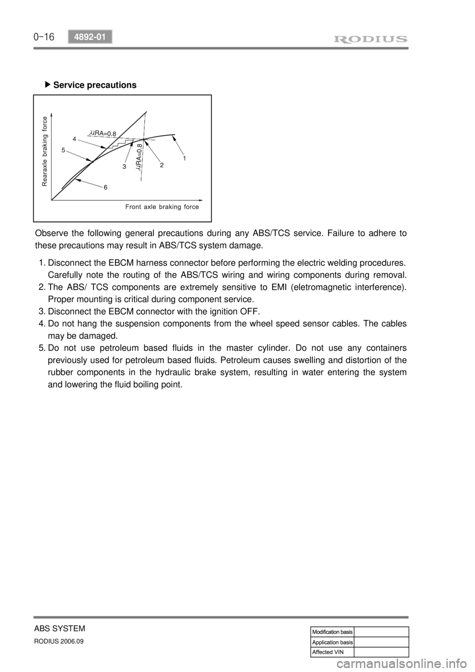
Service precautions ▶
Observe the following general precautions during any ABS/TCS service. Failure to adhere to
these precautions may result in ABS/TCS system damage.
Disconnect the EBCM harness connector before performing the electric welding procedures.
Carefully note the routing of the ABS/TCS wiring and wiring components during removal.
The ABS/ TCS components are extremely sensitive to EMI (eletromagnetic interference).
Proper mounting is critical during component service.
Disconnect the EBCM connector with the ignition OFF.
Do not hang the suspension components from the wheel speed sensor cables. The cables
may be damaged.
Do not use petroleum based fluids in the master cylinder. Do not use any containers
previously used for petroleum based fluids. Petroleum causes swelling and distortion of the
rubber components in the hydraulic brake system, resulting in water entering the system
and lowering the fluid boiling point. 1.
2.
3.
4.
5.