Page 225 of 272
If and when223
Safety First
Operating instructions
Tips and Maintenance
Te c h n i c a l D a t a
Side beam lights–Raise the bonnet. – Remove the loops
⇒fig. 154 in the direction of the arrow and
remove the cover.
– Pull on the cables to release the lamp holder from the casing ⇒fig. 155.
– Pull on the lamp and replace.
– To assemble proceed in reverse order.
– Fit the plastic cover and secure the loop.
Fig. 154 Side lightsFig. 155 Side lights
A1
AC
IBI_ANG_0707 Seite 223 Montag, 6. August 2007 3:59 15
Page 226 of 272
If and when
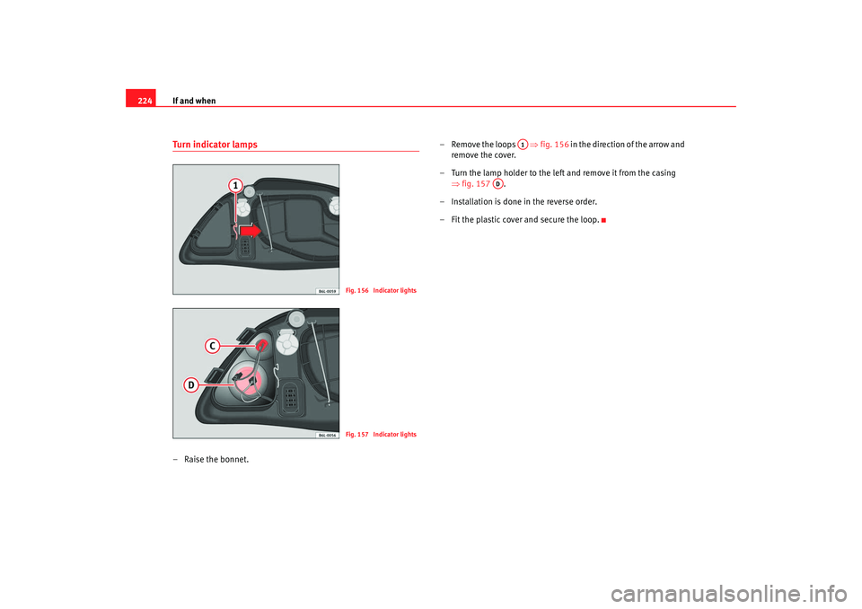
224Turn indicator lamps– Raise the bonnet. – Remove the loops
⇒fig. 156 in the direction of the arrow and
remove the cover.
– Turn the lamp holder to the left and remove it from the casing ⇒fig. 157 .
– Installation is done in the reverse order.
– Fit the plastic cover and secure the loop.
Fig. 156 Indicator lightsFig. 157 Indicator lights
A1
AD
IBI_ANG_0707 Seite 224 Montag, 6. August 2007 3:59 15
Page 227 of 272
If and when225
Safety First
Operating instructions
Tips and Maintenance
Te c h n i c a l D a t a
Fog lights– Remove the grille, taking out the bolt ⇒fig. 158 , carefully
pull the grille on the side of the screw and release the cover. – Undo the two fastening bolts
⇒fig. 158 and when released
unplug the connector.
– Release the headlight cover.
– Unplug the lamp cable.
– Undo the lamp retainer spring and remove.
– Remove the lamp and fit the new lamp in the same position, making sure it sits correctly.
– Press the retaining spring on the lamp base and clip on.
–Plug in the lamp cable.
–The assembly of the cover and the headlamp is carried out in
reverse order.
Fig. 158 Fog lightsFig. 159 Fog lights
AA
AF
IBI_ANG_0707 Seite 225 Montag, 6. August 2007 3:59 15
Page 228 of 272
If and when
226Side indicator lamps– Press the indicator to the left or to the right to remove the lamp.
– Remove the lamp holder from the indicator.
– Remove the failed bulb and replace with a new bulb.
– Insert the lamp holder in the indicator guide until it clicks into
place.
– First fit the indicator in the opening in the chassis, fastening the tabs ⇒fig. 160, and then fit in the lamp as shown by the
arrow ⇒fig. 160.
Rear light on tailgate: Accessing the rear lightSide light 1/ Fog light/ reverse light
–Open the tailgate.
Fig. 160 Side indicators
A1A2
Fig. 161 Rear light on
tailgateFig. 162 Rear light on
tailgate
IBI_ANG_0707 Seite 226 Montag, 6. August 2007 3:59 15
Page 229 of 272

If and when227
Safety First
Operating instructions
Tips and Maintenance
Te c h n i c a l D a t a
– Remove the plastic cover ⇒page 226, fig. 161 and the
plastic caps ⇒page 226, fig. 161 carefully levering with the
flat part of a screwdriver and ta king special care not to scratch
the paintwork.
– Extract the bolts ⇒page 226, fig. 162 and disconnect the
connector.
– Remove the rear light from its housing.Rear light on tailgate: Accessing the rear light
Side light 1/ Fog light/ reverse light
– Unscrew the bolts ⇒fig. 164 and take the lamp holder out.
– Press and rotate the large lamp holder to the left. For the small lamp, rotate and extract the lamp holder and pull on the lamp.
– Remove lamp and replace.
– Fit the lamp holder and fit.
– Fit the caps and the plastic cover ⇒fig. 163 .
NoteEnsure that all of the joints, sealing components and the plastic caps are
correctly fitted.
AA
AB
AC
Fig. 163 Rear light on
tailgate
Fig. 164 Access to the
lamp
AD
AB
AA
AB
IBI_ANG_0707 Seite 227 Montag, 6. August 2007 3:59 15
Page 230 of 272

If and when
228Rear lights on frameSide light 2/ Brake light/ Indicator light
– Open the tailgate. – Unscrew the screws
⇒fig. 165 using a flat-blade screwdriver.
– Move the rear light outwards and pull.
– If necessary, unplug the connector.
– Unscrew the bolt ⇒fig. 166.
– Take out the lamp holder.
– Press and rotate the lamps to the left.
– Remove faulty lamp and replace it.
– Proceed in the reverse order, pressing gently on the outer edge of the rear light (in the area of the metal clips).
Note
Make sure that when assembling all se als and rubbers are correctly fitted.Number plate light– Release transparent lamp cover by levering the tab with the flat
part of a screwdriver.
– Remove the defective lamp from the lamp holder, holding it in the centre, press to one side and fit new lamp.
– Fit lamp cover in its space, taking special care when replacing the rubber seal and press until it clicks into place.
Fig. 165 Rear lights on
bodyworkFig. 166 Rear lights on
bodywork
AF
AG
IBI_ANG_0707 Seite 228 Montag, 6. August 2007 3:59 15
Page 231 of 272

If and when229
Safety First
Operating instructions
Tips and Maintenance
Te c h n i c a l D a t a
Interior light and front reading light To r e m o v e g l a s s
– Insert a fine screwdriver between the casing and the glass
⇒fig. 167 .
– Carefully remove the glass, levering it to avoid possible damage.
To replace the lamps
– Pull the lamps outwards.
– To remove the central lamp, hold and press to one side.
Assembly
– Proceed in the reverse order, pressing gently on the outer edge of the side light. – First fit the glass with the fast
ening tabs over the frame of the
switch. Next press the front part until the two long tabs click on
the support.
Additional brake lights*Given the difficulty involved in the replac ement of this light it should be done
by the Technical Service.Glovebox light*– Insert screwdriver above, between the light and the glove box.
– Carefully remove the light Next lift the light out sideways.
– Replace the bulb.
– Insert the light on the connector side, first underneath then push at the top until it clicks into place.
Fig. 167 Front reading
light
IBI_ANG_0707 Seite 229 Montag, 6. August 2007 3:59 15
Page 232 of 272

If and when
230Boot light*– Extract the tulip shaped fitting by pressing on the inside edge of
this -arrow- using the flat side of a screwdriver ⇒fig. 168. – Press the lamp sideways and remove it from its housing
⇒fig. 169.
Jump-startingJump leads
The jump lead must have a sufficient wire cross section.If the engine fails to start because of a discharged battery, the battery can be
connected to the battery of anot her vehicle to start the engine.
Jump leads
Jump leads must comply with the standard DIN 72553 (see manufacturer's
documentation). The wire cross section must be at least 25 mm
2 for petrol
engines and at least 35 mm
2 for diesel engines.
Note
•
The vehicles must not touch each other, otherwise electricity could flow as
soon as the positive terminals are connected.
•
The discharged battery must be properly connected to the vehicles elec-
trical system.
Fig. 168 Luggage
compartment lightFig. 169 Luggage
compartment light
IBI_ANG_0707 Seite 230 Montag, 6. August 2007 3:59 15