2007 NISSAN TITAN clock
[x] Cancel search: clockPage 205 of 368
VOL (volume) button:
The VOL button allows the rear passengers to
adjust the headphone volume level.
(SPEAKER CONTROL) button:
Press this
button to turn the rear speakers
off and headphones on. Press thisbutton
again to turn rear seat speakers back on and
headphones off.
MODE button:
The MODE button allows the rear passengers to
change between AM, FM, CD, DVD and AUX.
The media options are listed on the face plate of
the rear audio controls. When a source of media
is selected, the media label will be illuminated.
SEEK button:
In AM or FM mode, the SEEK button allows the
rear seat passengers to find the next radio station
up or down the station band frequency.
In CD mode, the SEEK button allows the rear
passengers to find the next or previous selection
on the CD.NEXT button:
When the NEXT button is pressed while in AM or
FM mode, the radio will change to the next preset.
The NEXT button does not function while in SAT
radio mode or when playing a DVD or CD.
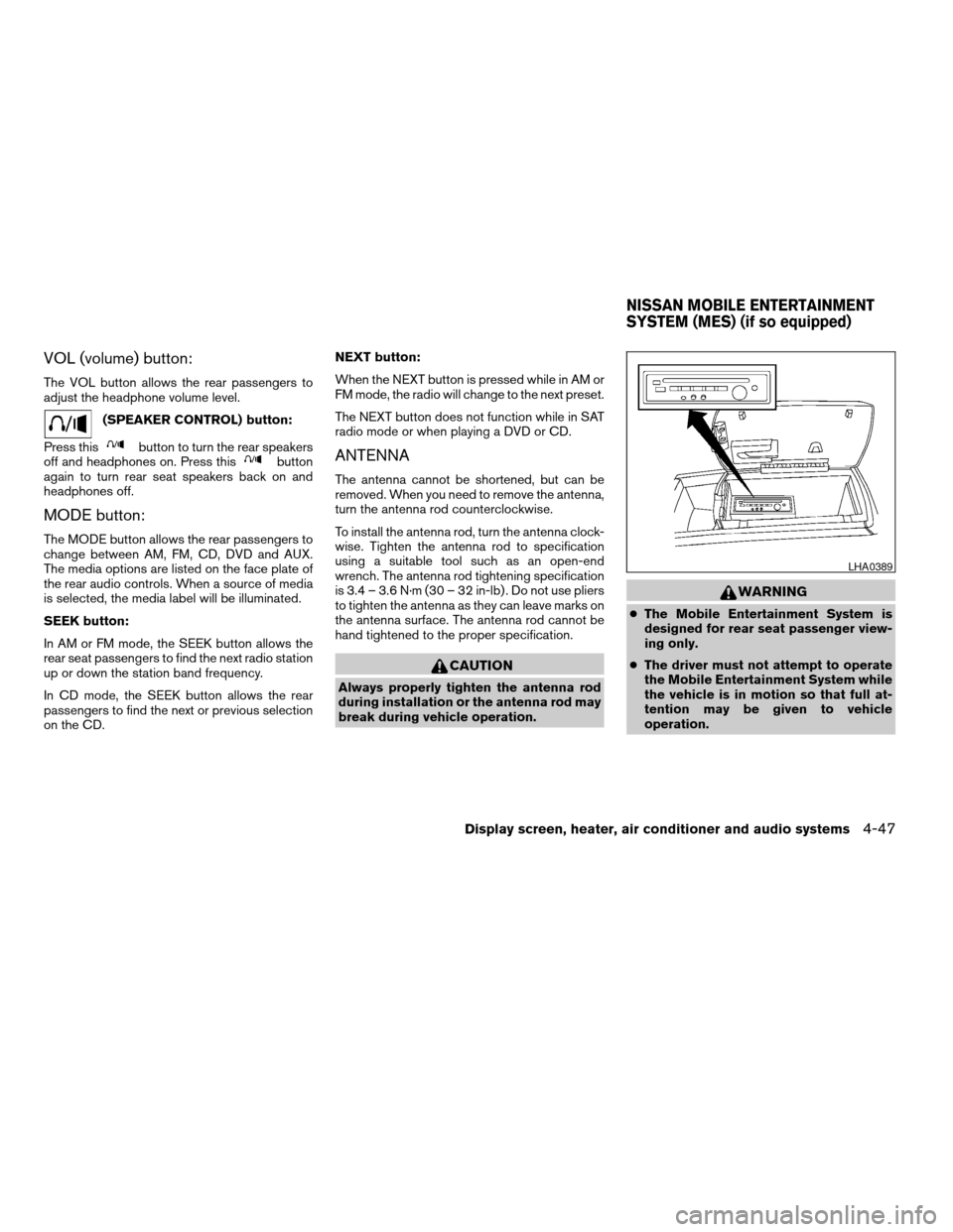
ANTENNA
The antenna cannot be shortened, but can be
removed. When you need to remove the antenna,
turn the antenna rod counterclockwise.
To install the antenna rod, turn the antenna clock-
wise. Tighten the antenna rod to specification
using a suitable tool such as an open-end
wrench. The antenna rod tightening specification
is 3.4 – 3.6 N·m (30 – 32 in-lb) . Do not use pliers
to tighten the antenna as they can leave marks on
the antenna surface. The antenna rod cannot be
hand tightened to the proper specification.
CAUTION
Always properly tighten the antenna rod
during installation or the antenna rod may
break during vehicle operation.
WARNING
cThe Mobile Entertainment System is
designed for rear seat passenger view-
ing only.
cThe driver must not attempt to operate
the Mobile Entertainment System while
the vehicle is in motion so that full at-
tention may be given to vehicle
operation.
LHA0389
NISSAN MOBILE ENTERTAINMENT
SYSTEM (MES) (if so equipped)
Display screen, heater, air conditioner and audio systems4-47
ZREVIEW COPYÐ2007 Titan(tzw)
Owners ManualÐUSA_English(nna)
07/09/06Ðtbrooks
X
Page 225 of 368

In order for the steering wheel to be locked, it
must be turned about 1/8 of a turn clockwise
from the straight up position.
To lock the steering wheel, turn the key to
the LOCK position. Remove the key. To
unlock the steering wheel, insert the key
and turn it gently while rotating the steer-
ing wheel slightly right and left.
If the key will not turn from the LOCK posi-
tion, turn the steering wheel to the left or
right while turning the key to unlock the
key cylinder.
KEY POSITIONS
LOCK: Normal parking position (0)
OFF: (Not used) (1)
ACC: (Accessories) (2)
This position activates electrical accessories
such as the radio when the engine is not running.
ON: Normal operating position (3)
This position turns on the ignition system and the
electrical accessories.
START: (4)
This position starts the engine. As soon as the
engine has started, release the key. It automati-
cally returns to the ON position.
NISSAN VEHICLE IMMOBILIZER
SYSTEM (if so equipped)
The NISSAN Vehicle Immobilizer System will not
allow the engine to start without the use of the
registered key.
If the engine fails to start using a registered key
(for example, when interference is caused by
another registered key, an automated toll road
device or automatic payment device on the key
ring) , restart the engine using the following pro-
cedures:
1. Leave the ignition switch in the ON position
for approximately 5 seconds.
2. Turn the ignition switch to the OFF or LOCK
position, and wait approximately 10 sec-
onds.
3. Repeat steps 1 and 2.
4. Restart the engine while holding the device
(which may have caused the interference)
separate from the registered key.
If the no start condition re-occurs, NISSAN rec-
ommends placing the registered key on a sepa-
rate key ring to avoid interference from other
devices.cMake sure the area around the vehicle is
clear.
cCheck fluid levels such as engine oil, cool-
ant, brake fluid, and window washer fluid as
frequently as possible, or at least whenever
you refuel.
cCheck that all windows and lights are clean.
cVisually inspect tires for their appearance
and condition. Also check tires for proper
inflation.
cLock all doors.
cPosition seat and adjust head restraints.
cAdjust inside and outside mirrors.
cFasten seat belts and ask all passengers to
do likewise.
cCheck the operation of warning lights when
the key is turned to the ON (3) position. See
“Warning/indicator lights and audible re-
minders” in the “Instruments and controls”
section of this manual.
BEFORE STARTING THE ENGINE
Starting and driving5-9
ZREVIEW COPYÐ2007 Titan(tzw)
Owners ManualÐUSA_English(nna)
07/09/06Ðtbrooks
X
Page 256 of 368
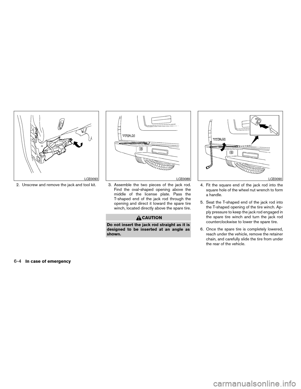
2. Unscrew and remove the jack and tool kit. 3. Assemble the two pieces of the jack rod.
Find the oval-shaped opening above the
middle of the license plate. Pass the
T-shaped end of the jack rod through the
opening and direct it toward the spare tire
winch, located directly above the spare tire.
CAUTION
Do not insert the jack rod straight as it is
designed to be inserted at an angle as
shown.4. Fit the square end of the jack rod into the
square hole of the wheel nut wrench to form
a handle.
5. Seat the T-shaped end of the jack rod into
the T-shaped opening of the tire winch. Ap-
ply pressure to keep the jack rod engaged in
the spare tire winch and turn the jack rod
counterclockwise to lower the spare tire.
6. Once the spare tire is completely lowered,
reach under the vehicle, remove the retainer
chain, and carefully slide the tire from under
the rear of the vehicle.
LCE0093LCE0089LCE0090
6-4In case of emergency
ZREVIEW COPYÐ2007 Titan(tzw)
Owners ManualÐUSA_English(nna)
07/09/06Ðtbrooks
X
Page 257 of 368
CAUTION
Be sure to center the spare tire suspend-
ing plate on the wheel and then lift the
spare tire.
Jacking up vehicle and removing the
damaged tire
WARNING
cNever get under the vehicle while it is
supported only by the jack. If it is nec-
essary to work under the vehicle, sup-
port it with safety stands.
cUse only the jack provided with your
vehicle to lift the vehicle. Do not use the
jack provided with your vehicle on other
vehicles. The jack is designed for lifting
only your vehicle during a tire change.
cUse the correct jack-up points. Never
use any other part of the vehicle for jack
support.
cNever jack up the vehicle more than
necessary.
cNever use blocks on or under the jack.cDo not start or run the engine while
vehicle is on the jack. It may cause the
vehicle to move. This is especially true
for vehicles with limited slip
differentials.
cDo not allow passengers to stay in the
vehicle while it is on the jack.
cNever run the engine with a wheel(s) off
the ground. It may cause the vehicle to
move.
Always refer to the illustration for the correct
placement and jack-up points for your specific
vehicle model and jack type.
Carefully read the caution label attached to
the jack body and the following instruc-
tions.
1. Loosen each wheel nut one or two turns by
turning counterclockwise with the wheel nut
wrench.Do not remove the wheel nuts
until the tire is off the ground.
In case of emergency6-5
ZREVIEW COPYÐ2007 Titan(tzw)
Owners ManualÐUSA_English(nna)
07/09/06Ðtbrooks
X
Page 281 of 368
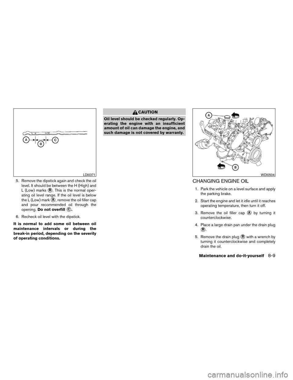
5. Remove the dipstick again and check the oil
level. It should be between the H (High) and
L (Low) marks
sB. This is the normal oper-
ating oil level range. If the oil level is below
the L (Low) mark
sA, remove the oil filler cap
and pour recommended oil through the
opening.Do not overfill
sC.
6. Recheck oil level with the dipstick.
It is normal to add some oil between oil
maintenance intervals or during the
break-in period, depending on the severity
of operating conditions.
CAUTION
Oil level should be checked regularly. Op-
erating the engine with an insufficient
amount of oil can damage the engine, and
such damage is not covered by warranty.
CHANGING ENGINE OIL
1. Park the vehicle on a level surface and apply
the parking brake.
2. Start the engine and let it idle until it reaches
operating temperature, then turn it off.
3. Remove the oil filler cap
sAby turning it
counterclockwise.
4. Place a large drain pan under the drain plug
sB.
5. Remove the drain plug
sBwith a wrench by
turning it counterclockwise and completely
drain the oil.
LDI0371WDI0504
Maintenance and do-it-yourself8-9
ZREVIEW COPYÐ2007 Titan(tzw)
Owners ManualÐUSA_English(nna)
07/09/06Ðtbrooks
X
Page 282 of 368
If the oil filter is to be changed, remove and
replace it at this time. See “Changing engine
oil filter” later in this section.
WARNING
cProlonged and repeated contact with
used engine oil may cause skin cancer.
cTry to avoid direct skin contact with
used oil. If skin contact is made, wash
thoroughly with soap or hand cleaner
as soon as possible.
cKeep used engine oil out of reach of
children.
CAUTION
Be careful not to burn yourself. The engine
oil may be hot.
cWaste oil must be disposed of prop-
erly.
cCheck your local regulations.
6. Clean and reinstall the drain plug and a new
washer. Securely tighten the drain plug with
a wrench. Do not use excessive force.
Drain plug tightening torque:
22 - 29 ft-lb (29 - 39 N·m)7. Refill engine with recommended oil through
the oil filler opening, then install the oil filler
cap securely.
See “Capacities and recommended
fuel/lubricants” in the “Technical and con-
sumer information” section of this manual for
drain and refill capacity.
The drain and refill capacity depends on the
oil temperature and drain time. Use these
specifications for reference only. Always use
the dipstick to determine when the proper
amount of oil is in the engine.
8. Start the engine. Check for leakage around
the drain plug and oil filter. Correct as re-
quired.
9. Turn the engine off and wait more than 10
minutes. Check the oil level with the dipstick.
Add engine oil if necessary.
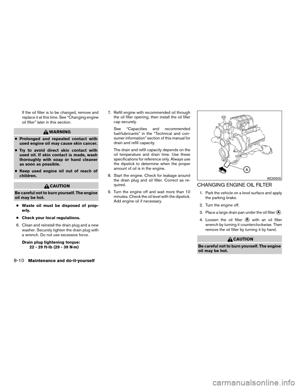
CHANGING ENGINE OIL FILTER
1. Park the vehicle on a level surface and apply
the parking brake.
2. Turn the engine off.
3. Place a large drain pan under the oil filter
sA.
4. Loosen the oil filter
sAwith an oil filter
wrench by turning it counterclockwise. Then
remove the oil filter by turning it by hand.
CAUTION
Be careful not to burn yourself. The engine
oil may be hot.
WDI0505
8-10Maintenance and do-it-yourself
ZREVIEW COPYÐ2007 Titan(tzw)
Owners ManualÐUSA_English(nna)
07/09/06Ðtbrooks
X
Page 297 of 368
FOG LIGHTS (if so equipped)
Replacing the fog light bulb
CAUTION
cHigh pressure halogen gas is sealed
inside the halogen bulb. The bulb may
break if the glass envelope is scratched
or the bulb is dropped.
cWhen handling the bulb, do not touch
the glass envelope.
cUse the same number and wattage as
originally installed:
Wattage 37.5 Bulb No. 899*
*: Always check with the Parts Depart-
ment at a NISSAN dealer for the latest
parts information.
cDo not leave the bulb out of the fog light
for a long period of time as dust, mois-
ture and smoke may enter the fog light
body and affect the performance of the
fog light.1. Disconnect the negative (-) battery cable.
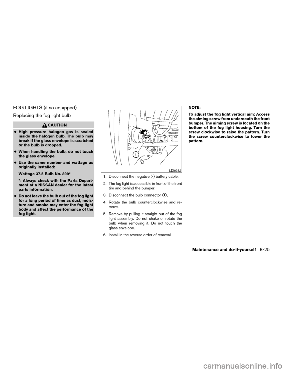
2. The fog light is accessible in front of the front
tire and behind the bumper.
3. Disconnect the bulb connector
s1.
4. Rotate the bulb counterclockwise and re-
move.
5. Remove by pulling it straight out of the fog
light assembly. Do not shake or rotate the
bulb when removing it. Do not touch the
glass envelope.
6. Install in the reverse order of removal.NOTE:
To adjust the fog light vertical aim: Access
the aiming screw from underneath the front
bumper. The aiming screw is located on the
bottom of the fog light housing. Turn the
screw clockwise to raise the pattern. Turn
the screw counterclockwise to lower the
pattern.
LDI0382
Maintenance and do-it-yourself8-25
ZREVIEW COPYÐ2007 Titan(tzw)
Owners ManualÐUSA_English(nna)
07/09/06Ðtbrooks
X
Page 332 of 368

3. Insert the cleat into the channel perpendicu-
lar to the channel as shown. Then rotate the
cleat clockwise 90° and slide it to the de-
sired location.
4. Position the cleat so the nubs on the bottom
fully seat into the channel detents.
LTI0103
LTI0104
9-18Technical and consumer information
ZREVIEW COPYÐ2007 Titan(tzw)
Owners ManualÐUSA_English(nna)
07/09/06Ðtbrooks
X