2007 NISSAN TIIDA Window warning
[x] Cancel search: Window warningPage 1 of 5883
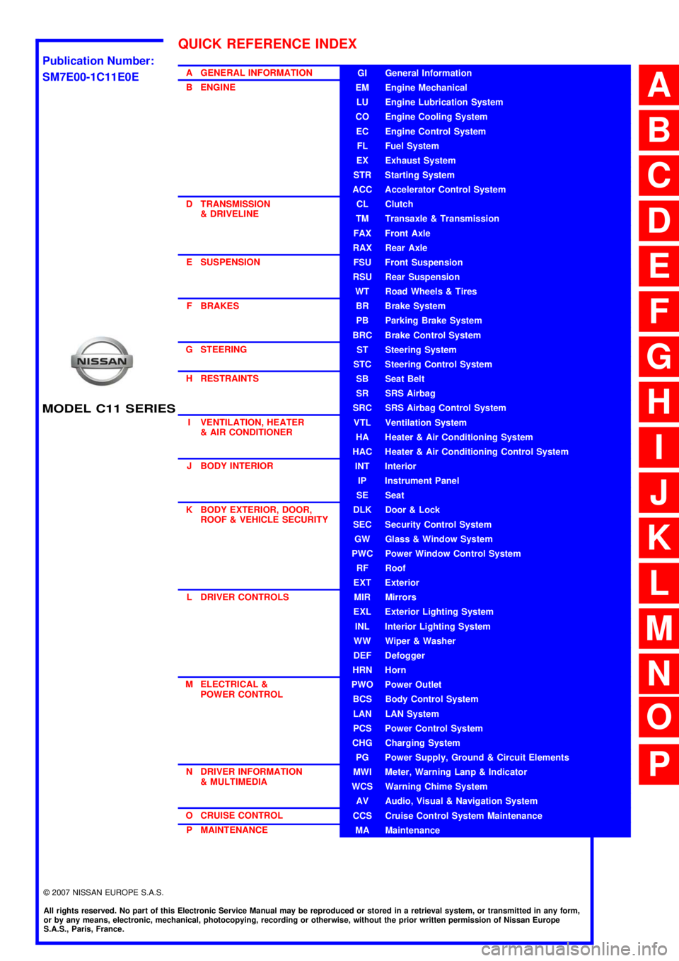
MODEL C11 SERIES
2007 NISSAN EUROPE S.A.S.
All rights reserved. No part of this Electronic Service Manual may be reproduced or stored in a retrieval system, or transmitted in any form,
or by any means, electronic, mechanical, photocopying, recording or otherwise, without the prior written permission of Nissan Europe
S.A.S., Paris, France.
A GENERAL INFORMATION
B ENGINE
D TRANSMISSION& DRIVELINE
E SUSPENSION F BRAKES
G STEERING H RESTRAINTS
I VENTILATION, HEATER & AIR CONDITIONER
J BODY INTERIOR
K BODY EXTERIOR, DOOR, ROOF & VEHICLE SECURITY
L DRIVER CONTROLS
M ELECTRICAL & POWER CONTROL
N DRIVER INFORMATION & MULTIMEDIA
O CRUISE CONTROL P MAINTENANCEGI General Information
EM Engine Mechanical
LU Engine Lubrication System
CO Engine Cooling System
EC Engine Control System
FL Fuel System
EX Exhaust System
STR Starting System
ACC Accelerator Control System
CL Clutch
TM Transaxle & Transmission
FAX Front Axle
RAX Rear Axle
FSU Front Suspension
RSU Rear Suspension
WT Road Wheels & Tires
BR Brake System
PB Parking Brake System
BRC Brake Control System
ST Steering System
STC Steering Control System
SB Seat Belt
SR SRS Airbag
SRC SRS Airbag Control System
VTL Ventilation System
HA Heater & Air Conditioning System
HAC Heater & Air Conditioning Control System
INT Interior
IP Instrument Panel
SE Seat
DLK Door & Lock
SEC Security Control System
GW Glass & Window System
PWC Power Window Control System
RF Roof
EXT Exterior
MIR Mirrors
EXL Exterior Lighting System
INL Interior Lighting System
WW Wiper & Washer
DEF Defogger
HRN Horn
PWO Power Outlet
BCS Body Control System
LAN LAN System
PCS Power Control System
CHG Charging System
PG Power Supply, Ground & Circuit Elements
MWI Meter, Warning Lanp & Indicator
WCS Warning Chime System
AV Audio, Visual & Navigation System
CCS Cruise Control System Maintenance
MA Maintenance
QUICK REFERENCE INDEX
A
B
C
D
E
F
G
H
I
J
K
L
M
N
O
P
M
Publication Number:
SM7E00-1C11E0E
Page 142 of 5883

BCS
BODY CONTROL SYSTEM
BCS-7
< FUNCTION DIAGNOSIS >
C
D
E
F
G
H
I
J
K
L B A
O
P N
FUNCTION DIAGNOSIS
BODY CONTROL SYSTEM
System DescriptionINFOID:0000000001451453
OUTLINE
BCM (Body Control Module) controls the various electrical components. It inputs the information required to
the control from CAN communication and the signal received from each switch and sensor.
BCM has combination switch reading function for reading the operation status of combination switches (light,
turn signal, wiper and washer) in addition to a function for controlling the operation of various electrical com-
ponents. It also has the signal transmission function as the passed point of signal and the power consump-
tion control function that reduces the power consumption with the ignition switch OFF.
BCM is equipped with the diagnosis function that performs the diagnosis with CONSULT-III and various set-
tings.
BCM control function list
System Refer to
Combination switch reading systemBCS-9, "
System Diagram"
Signal buffer systemBCS-13, "System Diagram"
Power consumption control systemBCS-14, "System Diagram"
Auto light systemEXL-12, "System Diagram"
Turn signal and hazard warning lamp systemEXL-22, "System Diagram"
Headlamp systemEXL-8, "System Diagram"
Front fog lamp systemEXL-19, "System Diagram"
Rear fog lamp systemEXL-21, "System Diagram"
Daytime light systemEXL-17, "System Diagram"
Interior room lamp control systemINL-5, "System Diagram"
Interior room lamp battery saver systemINL-12, "BATTERY SAVER : CONSULT-III Function (BCM - BATTERY SAV-
ER)"
Front wiper and washer systemWW-4, "System Diagram"
Rear wiper and washer systemWW-9, "System Diagram"
Headlamp washer systemWW-12, "System Diagram"
Warning chime systemWCS-4, "WARNING CHIME SYSTEM : System Diagram"
Door lock system WITH I-KEY, WITHOUT SUPER LOCK: DLK-20, "
DOOR LOCK AND UN-
LOCK SWITCH : System Diagram"
WITH I-KEY & SUPER LOCK: DLK-244, "DOOR LOCK AND UNLOCK
SWITCH : System Diagram"
WITHOUT I-KEY & SUPER LOCK: DLK-473, "DOOR LOCK AND UN-
LOCK SWITCH : System Diagram"
WITHOUT I-KEY, WITH SUPER LOCK: DLK-614, "DOOR LOCK AND UN-
LOCK SWITCH : System Diagram"
(NATS) Nissan anti-theft system WITH INTELLIGENT KEY SYSTEM: SEC-12, "System Diagram"
WITHOUT INTELLIGENT KEY SYSTEM: SEC-84, "System Diagram"
Rear window defogger systemDEF-6, "System Diagram"
Remote keyless entry system WITHOUT I-KEY & SUPER LOCK: DLK-475, "
REMOTE KEYLESS EN-
TRY : System Diagram"
WITHOUT I-KEY, WITH SUPER LOCK: DLK-614, "DOOR LOCK AND UN-
LOCK SWITCH : System Diagram"
Intelligent Key system WITH I-KEY, WITHOUT SUPER LOCK: DLK-23, "
INTELLIGENT KEY :
System Diagram"
WITH I-KEY & SUPER LOCK: DLK-244, "DOOR LOCK AND UNLOCK
SWITCH : System Diagram"
Page 151 of 5883

BCS-16
< FUNCTION DIAGNOSIS >
DIAGNOSIS SYSTEM (BCM)
DIAGNOSIS SYSTEM (BCM)
COMMON ITEM
COMMON ITEM : CONSULT-III Function (BCM - COMMON ITEM)INFOID:0000000001451463
APPLICATION ITEM
CONSULT-III performs the following functions via CAN communication with BCM.
SYSTEM APPLICATION
BCM can perform the following functions for each system.
NOTE:
It can perform the diagnosis modes except the following for all sub system selection items.
1: With remote keyless entry system
2: With Intelligent Key
BCM
Diagnosis mode Function Description
WORK SUPPORT Changes the setting for each system function.
SELF-DIAG RESULTS Displays the diagnosis results judged by BCM. Refer to BCS-54, "
DTCIndex".
CAN DIAG SUPPORT MNTR Monitors the reception status of CAN communication viewed from BCM.
DATA MONITOR The BCM input/output signals are displayed.
ACTIVE TEST The signals used to activate each device are forcibly supplied from BCM.
ECU IDENTIFICATION The BCM part number is displayed.
CONFIGURATION Enables to read and save the vehicle specification.
Enables to write the vehicle specification when replacing BCM.
System Sub system selection itemDiagnosis mode
WORK SUPPORT DATA MONITOR ACTIVE TEST
BCM BCM×
Door lock DOOR LOCK×××
Rear window defogger REAR DEFOGGER××
Warning chime BUZZER××
Interior room lamp timer INT LAMP×××
Remote keyless entry system
1MULTI REMOTE ENT×××
Exterior lamp HEAD LAMP×××
Wiper and washer WIPER×××
Turn signal and hazard warning lamps FLASHER××
Air conditioner AIR CONDITONER×
Intelligent Key system
2INTELLIGENT KEY×
Combination switch COMB SW×
Immobilizer IMMU××
Interior room lamp battery saver BATTERY SAVER×××
Trunk open (sedan)/Back door open
(hatch back)DOOR LOCK××
Vehicle security system THEFT ALM×××
Signal buffer system SIGNAL BUFFER××
PTC heater system PTC HEATER××
Page 153 of 5883

BCS-18
< FUNCTION DIAGNOSIS >
DIAGNOSIS SYSTEM (BCM)
*: With super lock
REAR WINDOW DEFOGGER
REAR WINDOW DEFOGGER : CONSULT-III Function (BCM - REAR DEFOGGER)
INFOID:0000000001451466
DATA MONITOR
ACTIVE TEST
BUZZER
BUZZER : CONSULT-III Function (BCM - BUZZER)INFOID:0000000001451467
DATA MONITOR
ACTIVE TEST
DOOR LOCK INDThis test is able to check door lock indicator (built in door lock and unlock switch on center
console) operation [ON/OFF].
TRUNK/BACK DOOR This test is able to check trunk/back door lock operation [LOCK (SET)/UNLOCK (RE-
LEASE)]. Test item Description
Monitor Item
[Unit]Description
ENGINE STATUS [RUN/
STOP]Indicates engine running status.
IGN ON SW [ON/OFF] Indicates condition of ignition switch in ON position.
REAR DEF SW [ON/OFF] Displays “Press (ON)/other (OFF)” status determined with the rear window defogger switch.
Test Item Description
REAR DEFOGGER Give a drive signal to the rear window defogger relay to activate it.
Monitor Item
[Unit]Description
IGN ON SW [ON/OFF] Ignition switch (ON) status judged by ignition power supply input.
PUSH SW
1 [ON/OFF]Ignition knob status.
KEY SW
2 [ON/OFF]Key switch status.
DOOR SW -DR [ON/OFF] Front door switch (driver side) status judged by BCM.
DOOR SW -AS [ON/OFF] Front door switch (passenger side) status judged by BCM.
DOOR SW -RR [ON/OFF] Rear door switch RH status judged by BCM.
DOOR SW -RL [ON/OFF] Rear door switch LH status judged by BCM.
BACK DOOR SW [ON/OFF] Back door switch status judged by BCM.
CDL LOCK SW [ON/OFF] Door lock/unlock switch status.
CDL UNLOCK SW [ON/OFF] Door lock/unlock switch status.
LIGHTING SW [ON/OFF]Lighting switch status judged by the lighting switch signal read with combination switch reading func-
tion.
TRNK OPNR SW [ON/OFF] Trunk switch status.
Test Item Description
LIGHT WARN ALM The light reminder warning operation can be checked by operating the relevant function (On/Off).
KEY REMINDER WARN The key reminder warning operation can be checked by operating the relevant function (On/Off).
Page 639 of 5883
![NISSAN TIIDA 2007 Service Repair Manual DLK-50
< FUNCTION DIAGNOSIS >[WITH I-KEY, WITHOUT SUPER LOCK]
DIAGNOSIS SYSTEM (BCM)
DIAGNOSIS SYSTEM (BCM)
COMMON ITEM
COMMON ITEM : CONSULT-III Function (BCM - COMMON ITEM)INFOID:0000000001396502
AP](/manual-img/5/57395/w960_57395-638.png "NISSAN TIIDA 2007 Service Repair Manual DLK-50
< FUNCTION DIAGNOSIS >[WITH I-KEY, WITHOUT SUPER LOCK]
DIAGNOSIS SYSTEM (BCM)
DIAGNOSIS SYSTEM (BCM)
COMMON ITEM
COMMON ITEM : CONSULT-III Function (BCM - COMMON ITEM)INFOID:0000000001396502
AP")
DLK-50
< FUNCTION DIAGNOSIS >[WITH I-KEY, WITHOUT SUPER LOCK]
DIAGNOSIS SYSTEM (BCM)
DIAGNOSIS SYSTEM (BCM)
COMMON ITEM
COMMON ITEM : CONSULT-III Function (BCM - COMMON ITEM)INFOID:0000000001396502
APPLICATION ITEM
CONSULT-III performs the following functions via CAN communication with BCM.
SYSTEM APPLICATION
BCM can perform the following functions for each system.
NOTE:
It can perform the diagnosis modes except the following for all sub system selection items.
DOOR LOCK
DOOR LOCK : CONSULT-III Function (BCM - DOOR LOCK)INFOID:0000000001396503
BCM CONSULT-III FUNCTION
CONSULT-III performs the following functions via CAN communication with BCM.
Diagnosis mode Function Description
WORK SUPPORT Changes the setting for each system function.
SELF-DIAG RESULTS Displays the diagnosis results judged by BCM. Refer to XX-XX, "*****"
.
CAN DIAG SUPPORT MNTR Monitors the reception status of CAN communication viewed from BCM.
DATA MONITOR The BCM input/output signals are displayed.
ACTIVE TEST The signals used to activate each device are forcibly supplied from BCM.
ECU IDENTIFICATION The BCM part number is displayed.
CONFIGURATION Enables to read and save the vehicle specification.
Enables to write the vehicle specification when replacing BCM.
System Sub system selection itemDiagnosis mode
WORK SUPPORT DATA MONITOR ACTIVE TEST
—BCM×
Door lock DOOR LOCK×××
Rear window defogger REAR DEFOGGER××
Warning chime BUZZER××
Interior room lamp timer INT LAMP×××
Remote keyless entry system MULTI REMOTE ENT×××
Exterior lamp HEAD LAMP×××
Wiper and washer WIPER×××
Turn signal and hazard warning lamps FLASHER××
Air conditioner AIR CONDITONER×
Intelligent Key system INTELLIGENT KEY×
Combination switch COMB SW×
Immobilizer IMMU××
Interior room lamp battery saver BATTERY SAVER×××
Trunk open TRUNK×
Vehicle security system THEFT ALM×××
Signal buffer system SIGNAL BUFFER××
PTC heater system PTC HEATER××
Page 642 of 5883
![NISSAN TIIDA 2007 Service Repair Manual DIAGNOSIS SYSTEM (INTELLIGENT KEY UNIT)
DLK-53
< FUNCTION DIAGNOSIS >[WITH I-KEY, WITHOUT SUPER LOCK]
C
D
E
F
G
H
I
J
L
MA
B
DLK
N
O
P
DIAGNOSIS SYSTEM (INTELLIGENT KEY UNIT)
CONSULT-III Function (INT](/manual-img/5/57395/w960_57395-641.png "NISSAN TIIDA 2007 Service Repair Manual DIAGNOSIS SYSTEM (INTELLIGENT KEY UNIT)
DLK-53
< FUNCTION DIAGNOSIS >[WITH I-KEY, WITHOUT SUPER LOCK]
C
D
E
F
G
H
I
J
L
MA
B
DLK
N
O
P
DIAGNOSIS SYSTEM (INTELLIGENT KEY UNIT)
CONSULT-III Function (INT")
DIAGNOSIS SYSTEM (INTELLIGENT KEY UNIT)
DLK-53
< FUNCTION DIAGNOSIS >[WITH I-KEY, WITHOUT SUPER LOCK]
C
D
E
F
G
H
I
J
L
MA
B
DLK
N
O
P
DIAGNOSIS SYSTEM (INTELLIGENT KEY UNIT)
CONSULT-III Function (INTELLIGENT KEY)INFOID:0000000001396506
APPLICATION ITEM
CONSULT-III performs the following functions via CAN communication with Intelligent Key unit.
WORK SUPPORT
SELF-DIAG RESULT
Refer to DLK-171, "DTCIndex".
DATA MONITOR
Diagnosis mode Function Description
WORK SUPPORT Changes the setting for each system function.
SELF-DIAG RESULTS Displays the diagnosis results judged by Intelligent Key unit.
CAN DIAG SUPPORT MNTR Monitors the reception status of CAN communication viewed from Intelligent Key unit.
DATA MONITOR The Intelligent Key unit input/output signals are displayed.
ACTIVE TEST The signals used to activate each device are forcibly supplied from Intelligent Key unit.
ECU IDENTIFICATION The Intelligent Key unit part number is displayed.
Support item Description Selection item Condition
CONFIRM KEY FOB IDIt can check whether Intelligent Key ID code
is registered or not.——
TAKE OUT FROM WINDOW WARNTake away warning chime (from window)
mode can be changed.ON Active
OFF Inactive
LOW BATT OF KEY FOB WARNIntelligent Key low battery warning mode can
be changed.ON Active
OFF Inactive
KEYLESS FUNCTIONDoor lock function with Intelligent Key can be
changed.ON Active
OFF Inactive
ANSWER BACK FUNCTION Buzzer reminder operation can be changed.ON Active
OFF Inactive
SELECTIVE UNLOCK FUNCTION Anti-hijack mode can be changed.ON Active
OFF Inactive
HAZARD ANSWER BACKHazard reminder operation mode can be
changed.Refer to DLK-45
.
ANSWER BACK WITH I-KEY LOCKBuzzer reminder operation (lock operation)
mode by each door request switch can be
changed. BUZZER Active
OFF Inactive
ANSWER BACK WITH I-KEY UNLOCKBuzzer reminder operation (unlock operation)
mode by each door request switch can be
changed.BUZZER Active
OFF Inactive
AUTO RELOCK TIMERAuto door lock operation mode can be
changed.OFF Inactive
2 min Active
ENGINE START BY I-KEYEngine start function (by Intelligent Key)
mode can be changed. ON Active
OFF Inactive
LOCK/UNLOCK BY I-KEYDoor lock function by door request switch can
be changed. ON Active
OFF Inactive
Page 786 of 5883
![NISSAN TIIDA 2007 Service Repair Manual WARNING FUNCTION SYMPTOMS
DLK-197
< SYMPTOM DIAGNOSIS >[WITH I-KEY, WITHOUT SUPER LOCK]
C
D
E
F
G
H
I
J
L
MA
B
DLK
N
O
P
WARNING FUNCTION SYMPTOMS
BUZZER (COMBINATION METER)
BUZZER (COMBINATION METER)](/manual-img/5/57395/w960_57395-785.png "NISSAN TIIDA 2007 Service Repair Manual WARNING FUNCTION SYMPTOMS
DLK-197
< SYMPTOM DIAGNOSIS >[WITH I-KEY, WITHOUT SUPER LOCK]
C
D
E
F
G
H
I
J
L
MA
B
DLK
N
O
P
WARNING FUNCTION SYMPTOMS
BUZZER (COMBINATION METER)
BUZZER (COMBINATION METER)")
WARNING FUNCTION SYMPTOMS
DLK-197
< SYMPTOM DIAGNOSIS >[WITH I-KEY, WITHOUT SUPER LOCK]
C
D
E
F
G
H
I
J
L
MA
B
DLK
N
O
P
WARNING FUNCTION SYMPTOMS
BUZZER (COMBINATION METER)
BUZZER (COMBINATION METER) : Symptom TableINFOID:0000000001396657
BUZZER (COMBINATION METER) OPERATION MALFUNCTION
NOTE:
Before performing the diagnosis in the following table, check “Work Flow”. Refer to DLK-16, "
Work Flow".
Check that vehicle is under the condition shown in “Conditions of vehicle” before starting diagnosis, and
check each symptom.
If the following symptoms are detected, check systems shown in the “Diagnosis/service procedure” column
in this order.
Conditions of Vehicle (Operating Conditions)
Warning chime functions operating conditions are extremely complicated. During operation confirmations,
reconfirm the list above twice in order to ensure proper operation. Refer to DLK-39, "
System Description".
Door lock function is normal.
Symptom Table
INTELLIGENT KEY WARNING BUZZER
INTELLIGENT KEY WARNING BUZZER : Symptom TableINFOID:0000000001396658
INTELLIGENT KEY WARNING BUZZER OPERATION MALFUNCTION
NOTE:
Before performing the diagnosis in the following table, check “Work Flow”. Refer to DLK-16, "
Work Flow".
Check that vehicle is under the condition shown in “Conditions of vehicle” before starting diagnosis, and
check each symptom.
If the following symptoms are detected, check systems shown in the “Diagnosis/service procedure” column
in this order.
Conditions of Vehicle (Operating Conditions)
Warning chime functions operating conditions are extremely complicated. During operation confirmations,
reconfirm the list above twice in order to ensure proper operation. Refer to DLK-39, "
System Description".
Symptom Table
Symptom Diagnosis/service procedure Reference page
Ignition knob return forgotten warning does not
operate properly.1. Check buzzer (combination meter).DLK-145
2. Check intermittent incident.XX-XX, "*****"
Ignition key warning does not operate properly.1. Check buzzer (combination meter).DLK-1452. Check intermittent incident.XX-XX, "*****"
OFF position warning does not operate properly.1. Check buzzer (combination meter).DLK-1452. Check intermittent incident.XX-XX, "*****"
Take away warning does
not operate properly.Take away through
window 1. Check buzzer (combination meter).DLK-145
2. Check intermittent incident. XX-XX, "*****"
Symptom Diagnosis/service procedureReference
page
Take away warning does
not operate properly.Any door open to all
doors closed.1.Check “TAKE OUT FROM WINDOW WARN” setting
in “WORK SUPPORT”.DLK-53
2. Check Intelligent Key warning buzzer.DLK-142
3. Check intermittent incident. XX-XX, "*****"
Page 787 of 5883
![NISSAN TIIDA 2007 Service Repair Manual DLK-198
< SYMPTOM DIAGNOSIS >[WITH I-KEY, WITHOUT SUPER LOCK]
WARNING FUNCTION SYMPTOMS
IGNITION KNOB SWITCH DOES NOT TURN ON
IGNITION KNOB SWITCH DOES NOT TURN ON : Symptom TableINFOID:00000000015233](/manual-img/5/57395/w960_57395-786.png "NISSAN TIIDA 2007 Service Repair Manual DLK-198
< SYMPTOM DIAGNOSIS >[WITH I-KEY, WITHOUT SUPER LOCK]
WARNING FUNCTION SYMPTOMS
IGNITION KNOB SWITCH DOES NOT TURN ON
IGNITION KNOB SWITCH DOES NOT TURN ON : Symptom TableINFOID:00000000015233")
DLK-198
< SYMPTOM DIAGNOSIS >[WITH I-KEY, WITHOUT SUPER LOCK]
WARNING FUNCTION SYMPTOMS
IGNITION KNOB SWITCH DOES NOT TURN ON
IGNITION KNOB SWITCH DOES NOT TURN ON : Symptom TableINFOID:0000000001523328
WARNING LAMP OPERATION MALFUNCTION
NOTE:
Before performing the diagnosis in the following table, check “Work Flow”. Refer to DLK-16, "
Work Flow".
Check that vehicle is under the condition shown in “Conditions of vehicle” before starting diagnosis, and
check each symptom.
If the following symptoms are detected, check systems shown in the “Diagnosis/service procedure” column
in this order.
Conditions of Vehicle (Operating Conditions)
Intelligent Key is registered.
Key is not inserted in ignition switch.
One or more registered Intelligent Keys are in the vehicle.
Symptom Table
KEY WARNING LAMP (GREEN) ILLUMINATES
Conditions of Vehicle (Operating Conditions)
Intelligent Key is registered.
Key is not inserted in ignition switch.
One or more registered Intelligent Keys are in the vehicle.
KEY WARNING LAMP (RED) ILLUMINATES
Conditions of Vehicle (Operating Conditions)
Door lock operation warn-
ing chime does not oper-
ate properly.Request switch oper-
ation1. Check Intelligent Key warning buzzer.DLK-1422. Check intermittent incident.XX-XX, "*****"
Intelligent Key button
operation1. Check Intelligent Key warning buzzer.DLK-142
2. Check intermittent incident.XX-XX, "*****"
Symptom Diagnosis/service procedureReference
page
Symptom Diagnosis/service procedureReference
page
OFF position warning does not operate properly.1. Check LOCK warning lamp. (RED blinking)DLK-147
2. Check intermittent incident.XX-XX, "*****"
Take away warning does
not operate properly.Any door open to all
doors closed.1. Check LOCK warning lamp. (RED blinking)DLK-147
2. Check intermittent incident. XX-XX, "*****"
Door is open1. Check LOCK warning lamp. (RED blinking)DLK-1472. Check intermittent incident.XX-XX, "*****"
Take away through
window1. Check LOCK warning lamp. (RED blinking)DLK-147
2. Check intermittent incident. XX-XX, "*****"
Intelligent Key low battery warning does not oper-
ate properly.1.Check “LOW BAT OF KEY FOB WARN” setting in
“WORK SUPPORT”.DLK-532. Check Intelligent Key battery.XX-XX, "*****"
3. Check KEY warning lamp. (GREEN blinking)DLK-146
4. Check intermittent incident.XX-XX, "*****"
Symptom Diagnosis/service procedure Reference page
Ignition switch does not turn on with Intelligent Key.
[KEY warning lamp (green) illuminates].1. Check steering lock solenoid.DLK-134
2. Replace Intelligent Key unit.SEC-79