Page 5785 of 5883

WCS-70
< ECU DIAGNOSIS >
BCM (BODY CONTROL MODULE)
1: Hatchback
2: Sedan
3: Manual A/C
4: Superlock
5: Remote keyless entry
6: Intelligent Key
7: LHD diesel69
(G)Ground Rear fog lamp OutputLighting switch
1ST and front
fog lamp switch
ONRear fog lamp switch OFF 0V
Rear fog lamp switch ON Battery voltage
70
(B)Ground Ground — — 0V
71
1
(V)Ground Rear wiper motor OutputRear wiper switch OFF 0V
Rear wiper switch ON Battery voltage
72
(LG)GroundBattery power sup-
plyInput — Battery voltage
73
(R)GroundInterior room lamp
power supplyOutputAfter passing the interior room lamp battery
saver operation time0V
Any other time after passing the interior room
lamp battery saver operation timeBattery voltage
74
(Y)GroundBattery power sup-
plyInput — Battery voltage
75
4
(V)Ground Super lock OutputWhen lock button of keyfob or Intelligent Key
is not pressed 0V
When lock button of keyfob or Intelligent Key
is pressed Battery voltage
76
(G)Ground Driver door unlock OutputDoor lock/un-
lock switchPressed to the unlock side Battery voltage
Pressed to the lock side 0V
77
(SB)Ground Door lock (All) OutputDoor lock/un-
lock switchPressed to the unlock side 0V
Pressed to the lock side Battery voltage
78
(L)GroundPower window pow-
er supplyOutput Ignition switchOFF or ACC 0V
ON Battery voltage
79
(Y)GroundBattery power sup-
plyInput — Battery voltage Te r m i n a l N o .
(Wire color)Description
ConditionReference Value
(Approx.)
Signal nameInput/
Output +−
Page 5791 of 5883

WCS-76
< SYMPTOM DIAGNOSIS >
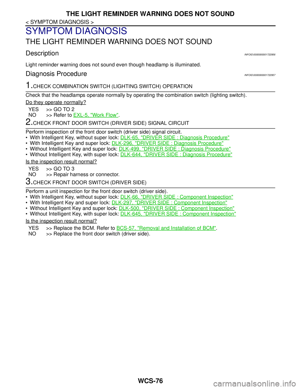
THE LIGHT REMINDER WARNING DOES NOT SOUND
SYMPTOM DIAGNOSIS
THE LIGHT REMINDER WARNING DOES NOT SOUND
DescriptionINFOID:0000000001722956
Light reminder warning does not sound even though headlamp is illuminated.
Diagnosis ProcedureINFOID:0000000001722957
1.CHECK COMBINATION SWITCH (LIGHTING SWITCH) OPERATION
Check that the headlamps operate normally by operating the combination switch (lighting switch).
Do they operate normally?
YES >> GO TO 2
NO >> Refer to EXL-5, "
Work Flow".
2.CHECK FRONT DOOR SWITCH (DRIVER SIDE) SIGNAL CIRCUIT
Perform inspection of the front door switch (driver side) signal circuit.
With Intelligent Key, without super lock: DLK-65, "
DRIVER SIDE : Diagnosis Procedure"
With Intelligent Key and super lock: DLK-296, "DRIVER SIDE : Diagnosis Procedure"
Without Intelligent Key and super lock: DLK-499, "DRIVER SIDE : Diagnosis Procedure"
Without Intelligent Key, with super lock: DLK-644, "DRIVER SIDE : Diagnosis Procedure"
Is the inspection result normal?
YES >> GO TO 3
NO >> Repair harness or connector.
3.CHECK FRONT DOOR SWITCH (DRIVER SIDE)
Perform a unit inspection for the front door switch (driver side).
With Intelligent Key, without super lock: DLK-66, "
DRIVER SIDE : Component Inspection"
With Intelligent Key and super lock: DLK-297, "DRIVER SIDE : Component Inspection"
Without Intelligent Key and super lock: DLK-500, "DRIVER SIDE : Component Inspection"
Without Intelligent Key, with super lock: DLK-645, "DRIVER SIDE : Component Inspection"
Is the inspection result normal?
YES >> Replace the BCM. Refer to BCS-57, "Removal and Installation of BCM".
NO >> Replace the front door switch (driver side).
Page 5793 of 5883

WCS-78
< SYMPTOM DIAGNOSIS >
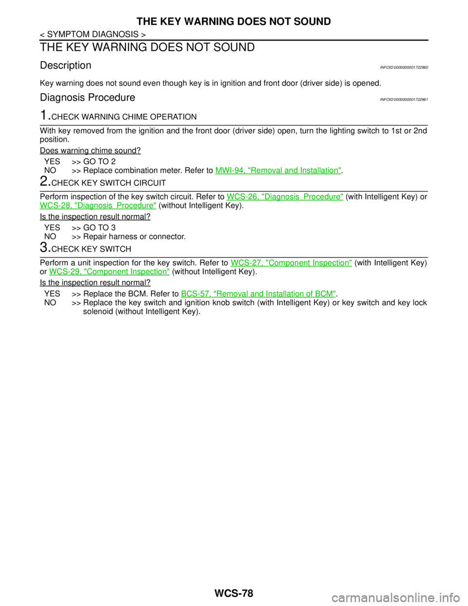
THE KEY WARNING DOES NOT SOUND
THE KEY WARNING DOES NOT SOUND
DescriptionINFOID:0000000001722960
Key warning does not sound even though key is in ignition and front door (driver side) is opened.
Diagnosis ProcedureINFOID:0000000001722961
1.CHECK WARNING CHIME OPERATION
With key removed from the ignition and the front door (driver side) open, turn the lighting switch to 1st or 2nd
position.
Does warning chime sound?
YES >> GO TO 2
NO >> Replace combination meter. Refer to MWI-94, "
Removal and Installation".
2.CHECK KEY SWITCH CIRCUIT
Perform inspection of the key switch circuit. Refer to WCS-26, "
DiagnosisProcedure" (with Intelligent Key) or
WCS-28, "
DiagnosisProcedure" (without Intelligent Key).
Is the inspection result normal?
YES >> GO TO 3
NO >> Repair harness or connector.
3.CHECK KEY SWITCH
Perform a unit inspection for the key switch. Refer to WCS-27, "
Component Inspection" (with Intelligent Key)
or WCS-29, "
Component Inspection" (without Intelligent Key).
Is the inspection result normal?
YES >> Replace the BCM. Refer to BCS-57, "Removal and Installation of BCM".
NO >> Replace the key switch and ignition knob switch (with Intelligent Key) or key switch and key lock
solenoid (without Intelligent Key).
Page 5816 of 5883

WW-14
< FUNCTION DIAGNOSIS >
DIAGNOSIS SYSTEM (BCM)
DIAGNOSIS SYSTEM (BCM)
COMMON ITEM
COMMON ITEM : CONSULT-III Function (BCM - COMMON ITEM)INFOID:0000000001366604
APPLICATION ITEM
CONSULT-III performs the following functions via CAN communication with BCM.
SYSTEM APPLICATION
BCM can perform the following functions for each system.
NOTE:
It can perform the diagnosis modes except the following for all sub system selection items.
WIPER
WIPER : CONSULT-III Function (BCM - WIPER)INFOID:0000000001366605
WORK SUPPORT
*:Factory setting
DATA MONITOR
Diagnosis mode Function Description
WORK SUPPORT Changes the setting for each system function.
SELF-DIAG RESULTS Displays the diagnosis results judged by BCM. Refer to BCS-54, "
DTCIndex".
CAN DIAG SUPPORT MNTR Monitors the reception status of CAN communication viewed from BCM.
DATA MONITOR The BCM input/output signals are displayed.
ACTIVE TEST The signals used to activate each device are forcibly supplied from BCM.
ECU IDENTIFICATION The BCM part number is displayed.
CONFIGURATION Enables to read and save the vehicle specification.
Enables to write the vehicle specification when replacing BCM.
System Sub system selection itemDiagnosis mode
WORK SUPPORT DATA MONITOR ACTIVE TEST
—BCM×
Exterior lamp HEAD LAMP×××
Wiper and washer WIPER×××
Combination switch COMB SW×
Back door switch DOOR LOCK××
Service itemSetting
itemDescription
WIPER SPEED
SETTINGON*With vehicle speed
(Front wiper intermittent time linked with the vehicle speed and wiper intermittent dial position)
OFFWithout vehicle speed
(Front wiper intermittent time linked with the wiper intermittent dial position)
Monitor Item
[Unit]Description
IGN ON SW Ignition switch ON status judged from ignition power supply.
IGN SW CAN Ignition switch ON status received from IPDM E/R with CAN communication.