Page 5575 of 5883
![NISSAN TIIDA 2007 Service Repair Manual SIDE OIL SEAL
TM-629
< ON-VEHICLE REPAIR >[5MT: RS5F91R]
C
E
F
G
H
I
J
K
L
MA
B
TM
N
O
P
ON-VEHICLE REPAIR
SIDE OIL SEAL
Exploded ViewINFOID:0000000001381685
Refer to TM-635, "Exploded View".
Removal NISSAN TIIDA 2007 Service Repair Manual SIDE OIL SEAL
TM-629
< ON-VEHICLE REPAIR >[5MT: RS5F91R]
C
E
F
G
H
I
J
K
L
MA
B
TM
N
O
P
ON-VEHICLE REPAIR
SIDE OIL SEAL
Exploded ViewINFOID:0000000001381685
Refer to TM-635, "Exploded View".
Removal](/manual-img/5/57395/w960_57395-5574.png)
SIDE OIL SEAL
TM-629
< ON-VEHICLE REPAIR >[5MT: RS5F91R]
C
E
F
G
H
I
J
K
L
MA
B
TM
N
O
P
ON-VEHICLE REPAIR
SIDE OIL SEAL
Exploded ViewINFOID:0000000001381685
Refer to TM-635, "Exploded View".
Removal and InstallationINFOID:0000000001381686
REMOVAL
1. Remove front drive shafts from transaxle assembly. Refer to XX-XX, "*****".
2. Remove differential side oil seal (1) using suitable tool.
CAUTION:
Do not damage transaxle case and clutch housing.
INSTALLATION
Installation is in the reverse order of removal.
⇐: Front
Install new differential side oil seal (1) to clutch housing and tran-
saxle case using Tool (A).
CAUTION:
Do not reuse differential side oil seal.
When installing, do not incline differential side oil seal.
Do not damage clutch housing or transaxle case.
Check oil level after installation. Refer to TM-628, "
Inspection".
PCIB1505E
Tool number : ST27862000 ( — )
Dimension “H
1” : 5.7 - 6.3 mm (0.224 - 0.248 in)
Dimension “H
2” : 16.4 - 17.0 mm (0.646 - 0.669 in)
PCIB1506E
Page 5857 of 5883

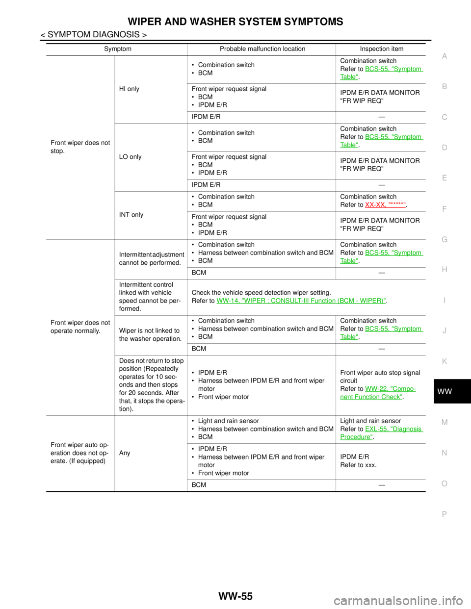
WIPER AND WASHER SYSTEM SYMPTOMS
WW-55
< SYMPTOM DIAGNOSIS >
C
D
E
F
G
H
I
J
K
MA
B
WW
N
O
P
Front wiper does not
stop.HI only Combination switch
BCMCombination switch
Refer to BCS-55, "
Symptom
Ta b l e".
Front wiper request signal
BCM
IPDM E/RIPDM E/R DATA MONITOR
"FR WIP REQ"
IPDM E/R —
LO only Combination switch
BCMCombination switch
Refer to BCS-55, "
Symptom
Ta b l e".
Front wiper request signal
BCM
IPDM E/RIPDM E/R DATA MONITOR
"FR WIP REQ"
IPDM E/R —
INT only Combination switch
BCMCombination switch
Refer to XX-XX, "*****"
.
Front wiper request signal
BCM
IPDM E/RIPDM E/R DATA MONITOR
"FR WIP REQ"
Front wiper does not
operate normally.Intermittent adjustment
cannot be performed. Combination switch
Harness between combination switch and BCM
BCMCombination switch
Refer to BCS-55, "
Symptom
Ta b l e".
BCM —
Intermittent control
linked with vehicle
speed cannot be per-
formed.Check the vehicle speed detection wiper setting.
Refer to WW-14, "
WIPER : CONSULT-III Function (BCM - WIPER)".
Wiper is not linked to
the washer operation. Combination switch
Harness between combination switch and BCM
BCMCombination switch
Refer to BCS-55, "
Symptom
Ta b l e".
BCM —
Does not return to stop
position (Repeatedly
operates for 10 sec-
onds and then stops
for 20 seconds. After
that, it stops the opera-
tion). IPDM E/R
Harness between IPDM E/R and front wiper
motor
Front wiper motorFront wiper auto stop signal
circuit
Refer to WW-22, "
Compo-
nent Function Check".
Front wiper auto op-
eration does not op-
erate. (If equipped)Any Light and rain sensor
Harness between combination switch and BCM
BCMLight and rain sensor
Refer to EXL-55, "
Diagnosis
Procedure".
IPDM E/R
Harness between IPDM E/R and front wiper
motor
Front wiper motorIPDM E/R
Refer to xxx.
BCM — Symptom Probable malfunction location Inspection item
Page 5877 of 5883
RAIN SENSOR
WW-75
< ON-VEHICLE REPAIR >
C
D
E
F
G
H
I
J
K
MA
B
WW
N
O
P
RAIN SENSOR
Exploded ViewINFOID:0000000001366670
Refer to XX-XX, "*****".
Removal and InstallationINFOID:0000000001366671
Refer to XX-XX, "*****".
Page 5882 of 5883
WW-80
< ON-VEHICLE REPAIR >
REAR WASHER NOZZLE AND TUBE
REAR WASHER NOZZLE AND TUBE
Washer Tube LayoutINFOID:0000000001366677
NOTE:
Connect the check valve (2) to the washer fluid tube (1) so that the
directional arrow on the check valve (2) points towards the washer
nozzle tube (3).
Removal and InstallationINFOID:0000000001366678
REAR WASHER NOZZLE
Removal
1. Remove the back door window garnish. Refer to XX-XX, "*****".
2. Disconnect rear washer tube from rear washer nozzle.
3. Release retaining clips and remove washer nozzle.
Installation
1 Washer fluid reservoir 2 Washer fluid tube to rear door 3 Rear washer nozzle
4Check valve
LKIA0790E
WKIA4242E
LKIA0545E
Page 5883 of 5883
REAR WASHER NOZZLE AND TUBE
WW-81
< ON-VEHICLE REPAIR >
C
D
E
F
G
H
I
J
K
MA
B
WW
N
O
P
Installation is in the reverse order of removal.
NOTE:
Inspect rear washer nozzle for proper spray pattern, adjust as necessary. Refer to XX-XX, "*****"
.
AdjustmentINFOID:0000000001366679
Adjust the washer nozzle (1) to specification (A) using suitable tool
as shown.
Washer nozzle (1)
Washer spray area (A)
Black print area (B)
Wiping area edge (C)
30 mm (1.18 in) (D)
161 mm (6.34 in) (E)
AWLIA0142ZZ
AWLIA0143ZZ