Page 3126 of 5883
EXT-22
< ON-VEHICLE REPAIR >
FENDER PROTECTOR
FENDER PROTECTOR
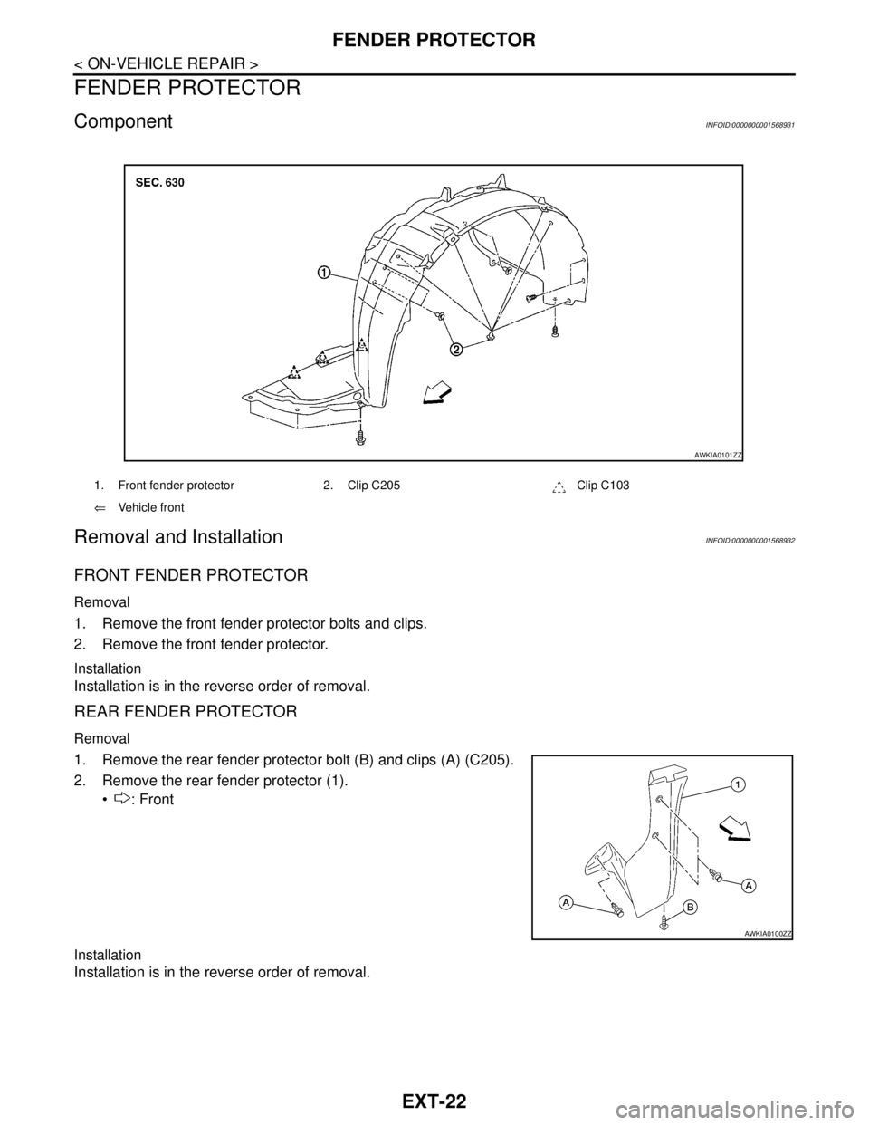
ComponentINFOID:0000000001568931
Removal and InstallationINFOID:0000000001568932
FRONT FENDER PROTECTOR
Removal
1. Remove the front fender protector bolts and clips.
2. Remove the front fender protector.
Installation
Installation is in the reverse order of removal.
REAR FENDER PROTECTOR
Removal
1. Remove the rear fender protector bolt (B) and clips (A) (C205).
2. Remove the rear fender protector (1).
: Front
Installation
Installation is in the reverse order of removal.
1. Front fender protector 2. Clip C205 Clip C103
⇐Vehicle front
AWKIA0101ZZ
AWKIA0100ZZ
Page 3318 of 5883
HA-36
< ON-VEHICLE REPAIR >
COMPRESSOR
4. Reposition the RH air guide out of the way.
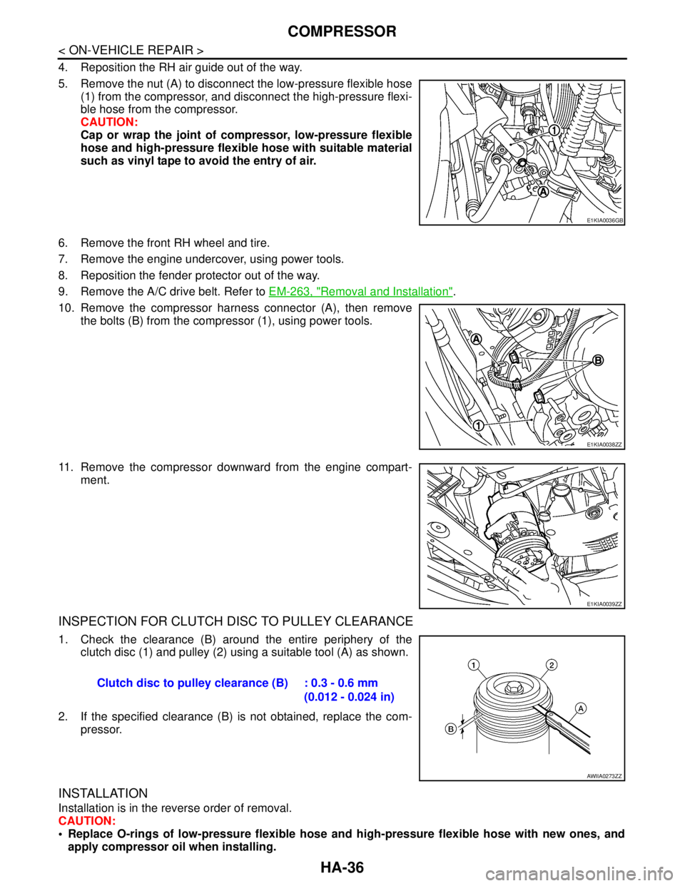
5. Remove the nut (A) to disconnect the low-pressure flexible hose
(1) from the compressor, and disconnect the high-pressure flexi-
ble hose from the compressor.
CAUTION:
Cap or wrap the joint of compressor, low-pressure flexible
hose and high-pressure flexible hose with suitable material
such as vinyl tape to avoid the entry of air.
6. Remove the front RH wheel and tire.
7. Remove the engine undercover, using power tools.
8. Reposition the fender protector out of the way.
9. Remove the A/C drive belt. Refer to EM-263, "
Removal and Installation".
10. Remove the compressor harness connector (A), then remove
the bolts (B) from the compressor (1), using power tools.
11. Remove the compressor downward from the engine compart-
ment.
INSPECTION FOR CLUTCH DISC TO PULLEY CLEARANCE
1. Check the clearance (B) around the entire periphery of the
clutch disc (1) and pulley (2) using a suitable tool (A) as shown.
2. If the specified clearance (B) is not obtained, replace the com-
pressor.
INSTALLATION
Installation is in the reverse order of removal.
CAUTION:
Replace O-rings of low-pressure flexible hose and high-pressure flexible hose with new ones, and
apply compressor oil when installing.
E1KIA0036GB
E1KIA0038ZZ
E1KIA0039ZZ
Clutch disc to pulley clearance (B) : 0.3 - 0.6 mm
(0.012 - 0.024 in)
AWIIA0273ZZ
Page 4237 of 5883

LU-30
< ON-VEHICLE REPAIR >[K9K]
OIL COOLER
OIL COOLER
Exploded ViewINFOID:0000000001381543
Removal and InstallationINFOID:0000000001381544
CAUTION:
Be careful not to get burned when the engine and engine oil are hot.
When removing, prepare a shop cloth to absorb any oil leakage or spillage.
Completely wipe off any oil that adhere to the engine and the vehicle.
REMOVAL
1. Remove engine undercover using power tool.
2. Drain engine coolant. Refer to CO-58, "
Draining".
CAUTION:
Perform when engine is cold.
3. Remove RH front wheel. Refer to WT-6, "
Rotation".
4. Remove RH fender protector. Refer to EXT-22, "
Removal and Installation".
5. Remove drive belt. Refer to EM-263, "
Removal and Installation".
6. Remove generator and position aside. Refer to CHG-43, "
Removal and Installation".
7. Remove A/C compressor and position aside. Refer to HA-35, "
Removal and Installation of Compressor -
K9K".
8. Remove oil filter and oil filter bracket. Refer to LU-28, "
Replacement".
1. Cylinder block 2. Water pipe 3. O-ring
4. O-ring 5. O-ring 6. Oil cooler
7. Connecting stud 8. O-ring 9. Oil filter bracket
10. Oil pressure switch 11. Oil filter 12. O-ring
13. Connecting bolt
A. To radiator lower hose B. To water pump
E1BIA0011GB
Page 4239 of 5883
LU-32
< ON-VEHICLE REPAIR >[K9K]
OIL PUMP
OIL PUMP
Exploded ViewINFOID:0000000001381546
Removal and InstallationINFOID:0000000001381547
REMOVAL
1. Remove the battery negative cable.
2. Remove the engine undercover.
3. Remove the RH front wheel and tire. Refer to WT-6, "
Rotation".
4. Remove RH fender protector. Refer to EXT-22, "
Removal and Installation".
5. Remove front driveshaft assembly RH. Refer to FA X - 11 , "
Removal and Installation (Right Side)".
6. Remove driveshaft center bearing bracket.
7. Remove lower torque rod. Refer to EM-302, "
Exploded View".
8. Remove oil pan. Refer to EM-284, "
Removal and Installation".
9. Remove oil pump drive chain.
10. Remove oil pump assembly.
INSTALLATION
Installation is in the reverse order of removal.
1. Oil pump drive chain 2. Crankshaft sprocket (oil pump drive
chain)3. Oil pump
E1BIA0028GB