2007 NISSAN TIIDA wheel bolt torque
[x] Cancel search: wheel bolt torquePage 3195 of 5883
GI-1
GENERAL INFORMATION
C
D
E
F
G
H
I
J
K
L
MB
GI
SECTION GI
N
O
P
CONTENTS
GENERAL INFORMATION
HOW TO USE THIS MANUAL ......................3
HOW TO USE THIS MANUAL ............................3
Description ................................................................3
Terms ........................................................................3
Units ..........................................................................3
Contents ....................................................................3
Relation between Illustrations and Descriptions .......4
Component ................................................................4
How to Follow Trouble Diagnosis ..............................5
How to Read Wiring Diagram ....................................9
Abbreviations ..........................................................16
HOW TO FOLLOW TROUBLE DIAGNOSES ....18
Description ..............................................................18
How to Follow Test Groups in Trouble Diagnosis ....18
Key to Symbols Signifying Measurements or Pro-
cedures ...................................................................
19
HOW TO READ WIRING DIAGRAMS ...............21
Connector symbols .................................................21
Sample/wiring diagram -example- ...........................22
Description ..............................................................23
ABBREVIATIONS ..............................................25
Abbreviation List ......................................................25
TIGHTENING TORQUE OF STANDARD
BOLTS ................................................................
26
Tightening Torque Table .........................................26
RECOMMENDED CHEMICAL PRODUCTS
AND SEALANTS ................................................
27
Recommended Chemical Products and Sealants ....27
TERMINOLOGY .................................................28
SAE J1930 Terminology List ...................................28
FEATURES OF NEW MODEL .....................32
IDENTIFICATION INFORMATION .....................32
Model Variation .......................................................32
Dimensions ..............................................................41
Wheels & Tires ........................................................42
PRECAUTION ..............................................43
PRECAUTIONS .................................................43
Description ...............................................................43
Precaution for Supplemental Restraint System
(SRS) "AIR BAG" and "SEAT BELT PRE-TEN-
SIONER" .................................................................
43
Precaution Necessary for Steering Wheel Rota-
tion After Battery Disconnect ...................................
43
General Precaution ..................................................44
Precaution for Three Way Catalyst ..........................45
Precaution for Fuel (Unleaded Regular Gasoline
Recommended) .......................................................
45
Precaution for Multiport Fuel Injection System or
Engine Control System ............................................
46
Precaution for Hoses ...............................................46
Precaution for Engine Oils .......................................47
Precaution for Air Conditioning ................................47
LIFTING POINT .................................................48
Special Service Tool ................................................48
Garage Jack and Safety Stand and 2-Pole Lift .......48
Board-On Lift ...........................................................49
TOW TRUCK TOWING .....................................50
Tow Truck Towing ...................................................50
Vehicle Recovery (Freeing a Stuck Vehicle) ...........50
BASIC INSPECTION ...................................51
SERVICE INFORMATION FOR ELECTRICAL
INCIDENT ..........................................................
51
Work Flow ................................................................51
Control Units and Electrical Parts ............................51
How to Check Terminal ...........................................52
Intermittent Incident .................................................55
Circuit Inspection .....................................................58
CONSULT-III CHECKING SYSTEM .................63
Page 4580 of 5883
RSU-8
< ON-VEHICLE REPAIR >
SHOCK ABSORBER
ON-VEHICLE REPAIR
SHOCK ABSORBER
Removal and InstallationINFOID:0000000001724578
REMOVAL
1. Remove rear tires from vehicle using power tool.
2. Remove wheel sensor from wheel hub and bearing assembly and rear suspension beam. Refer to BRC-
83, "Removal and Installation" .
CAUTION:
Do not pull on wheel sensor harness.
3. Remove shock absorber mask from trunk side finisher using a flat-bladed screwdriver. Refer to INT-24,
"Removal and Installation" .
CAUTION:
Wrap the tip of a screwdriver with cloth to avoid damaging components.
4. Set jack under rear suspension beam.
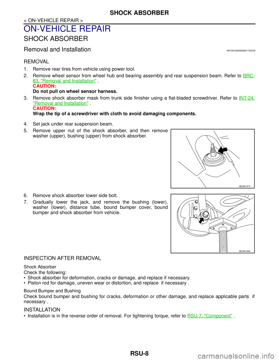
5. Remove upper nut of the shock absorber, and then remove
washer (upper), bushing (upper) from shock absorber.
6. Remove shock absorber lower side bolt.
7. Gradually lower the jack, and remove the bushing (lower),
washer (lower), distance tube, bound bumper cover, bound
bumper and shock absorber from vehicle.
INSPECTION AFTER REMOVAL
Shock Absorber
Check the following:
Shock absorber for deformation, cracks or damage, and replace if necessary.
Piston rod for damage, uneven wear or distortion, and replace if necessary .
Bound Bumper and Bushing
Check bound bumper and bushing for cracks, deformation or other damage, and replace applicable parts if
necessary .
INSTALLATION
Installation is in the reverse order of removal. For tightening torque, refer to RSU-7, "Component" .
SEIA0147J
SEIA0146J
Page 4582 of 5883
RSU-10
< ON-VEHICLE REPAIR >
COIL SPRING
COIL SPRING
Removal and InstallationINFOID:0000000001724579
REMOVAL
1. Remove rear tires from vehicle using power tool.
2. Remove wheel sensor from wheel hub and bearing assembly. Refer to BRC-83, "
Removal and Installa-
tion" .
CAUTION:
Do not pull on wheel sensor harness.
3. Separate brake tube from wheel cylinder. Refer to BR-15, "
Rear Brake Tube and Hose" .
4. Set jack under rear suspension beam.
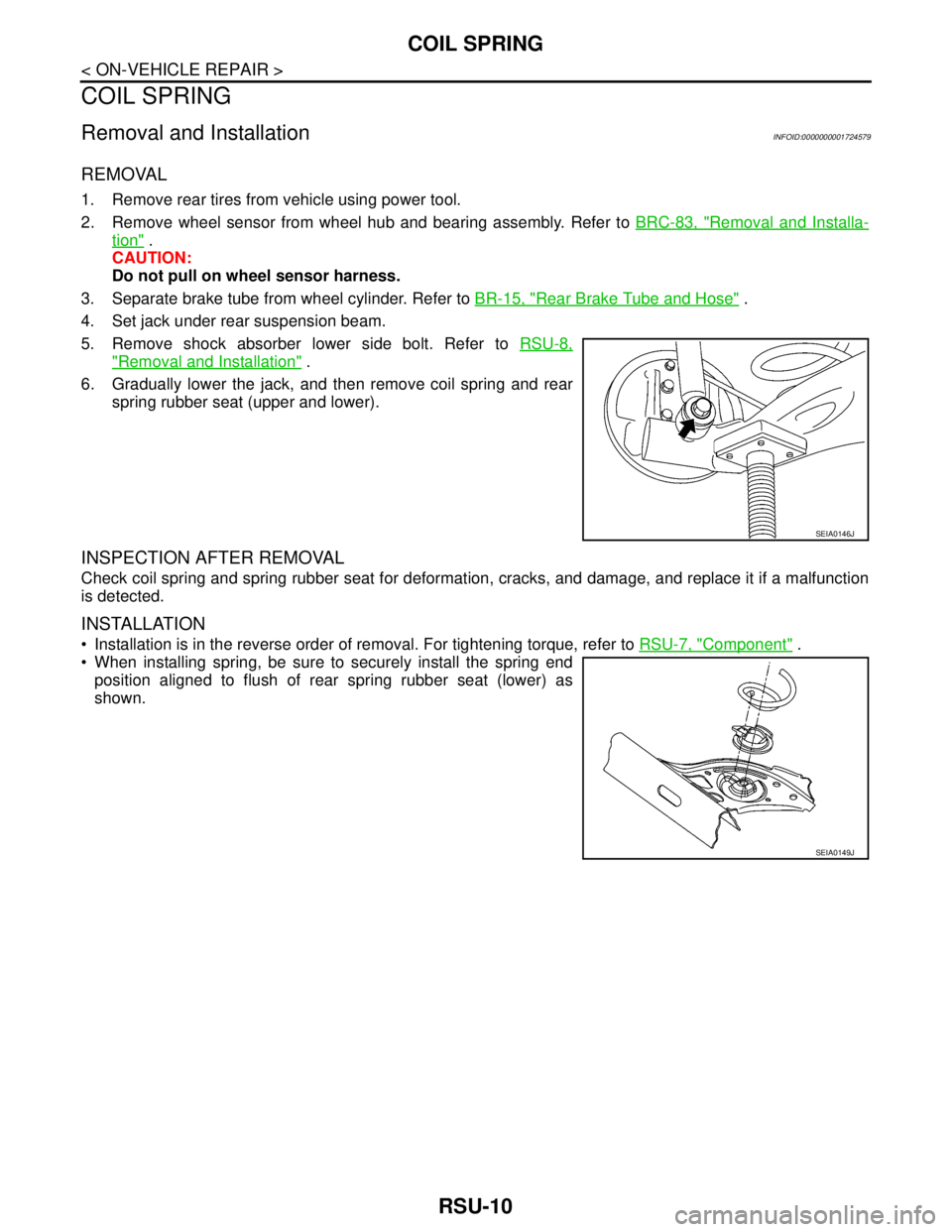
5. Remove shock absorber lower side bolt. Refer to RSU-8,
"Removal and Installation" .
6. Gradually lower the jack, and then remove coil spring and rear
spring rubber seat (upper and lower).
INSPECTION AFTER REMOVAL
Check coil spring and spring rubber seat for deformation, cracks, and damage, and replace it if a malfunction
is detected.
INSTALLATION
Installation is in the reverse order of removal. For tightening torque, refer to RSU-7, "Component" .
When installing spring, be sure to securely install the spring end
position aligned to flush of rear spring rubber seat (lower) as
shown.
SEIA0146J
SEIA0149J
Page 4583 of 5883
REAR SUSPENSION BEAM
RSU-11
< ON-VEHICLE REPAIR >
C
D
F
G
H
I
J
K
L
MA
B
RSU
N
O
P
REAR SUSPENSION BEAM
Removal and InstallationINFOID:0000000001724580
REMOVAL
1. Remove rear tires from vehicle using power tool.
2. Separate parking brake rear cable from rear drum brake and rear suspension beam. Refer to PB-4, "
On-
Vehicle Service" .
3. Remove wheel sensor and wheel sensor harness from wheel hub and bearing assembly and rear suspen-
sion beam. Refer to BRC-83, "
Removal and Installation" .
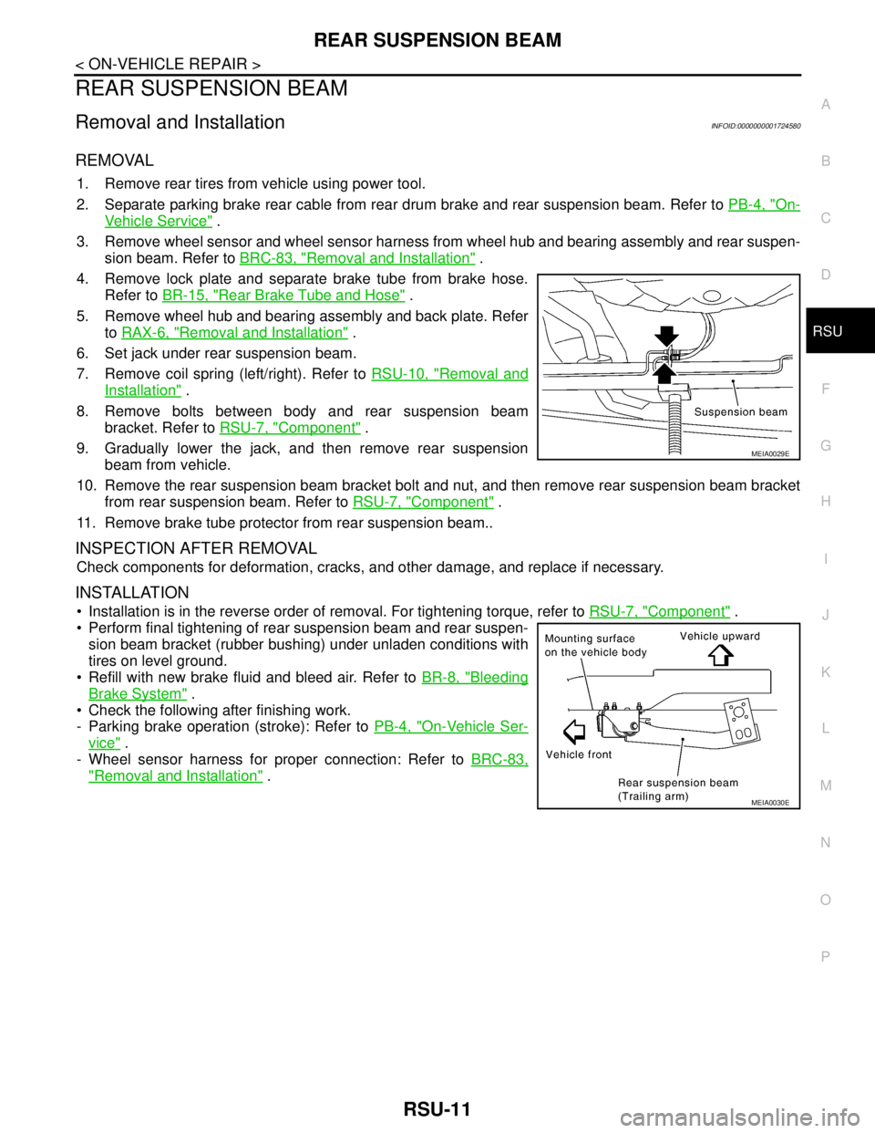
4. Remove lock plate and separate brake tube from brake hose.
Refer to BR-15, "
Rear Brake Tube and Hose" .
5. Remove wheel hub and bearing assembly and back plate. Refer
to RAX-6, "
Removal and Installation" .
6. Set jack under rear suspension beam.
7. Remove coil spring (left/right). Refer to RSU-10, "
Removal and
Installation" .
8. Remove bolts between body and rear suspension beam
bracket. Refer to RSU-7, "
Component" .
9. Gradually lower the jack, and then remove rear suspension
beam from vehicle.
10. Remove the rear suspension beam bracket bolt and nut, and then remove rear suspension beam bracket
from rear suspension beam. Refer to RSU-7, "
Component" .
11. Remove brake tube protector from rear suspension beam..
INSPECTION AFTER REMOVAL
Check components for deformation, cracks, and other damage, and replace if necessary.
INSTALLATION
Installation is in the reverse order of removal. For tightening torque, refer to RSU-7, "Component" .
Perform final tightening of rear suspension beam and rear suspen-
sion beam bracket (rubber bushing) under unladen conditions with
tires on level ground.
Refill with new brake fluid and bleed air. Refer to BR-8, "
Bleeding
Brake System" .
Check the following after finishing work.
- Parking brake operation (stroke): Refer to PB-4, "
On-Vehicle Ser-
vice" .
- Wheel sensor harness for proper connection: Refer to BRC-83,
"Removal and Installation" .
MEIA0029E
MEIA0030E
Page 4859 of 5883
ST-4
< PREPARATION >
PREPARATION
PREPARATION
PREPARATION
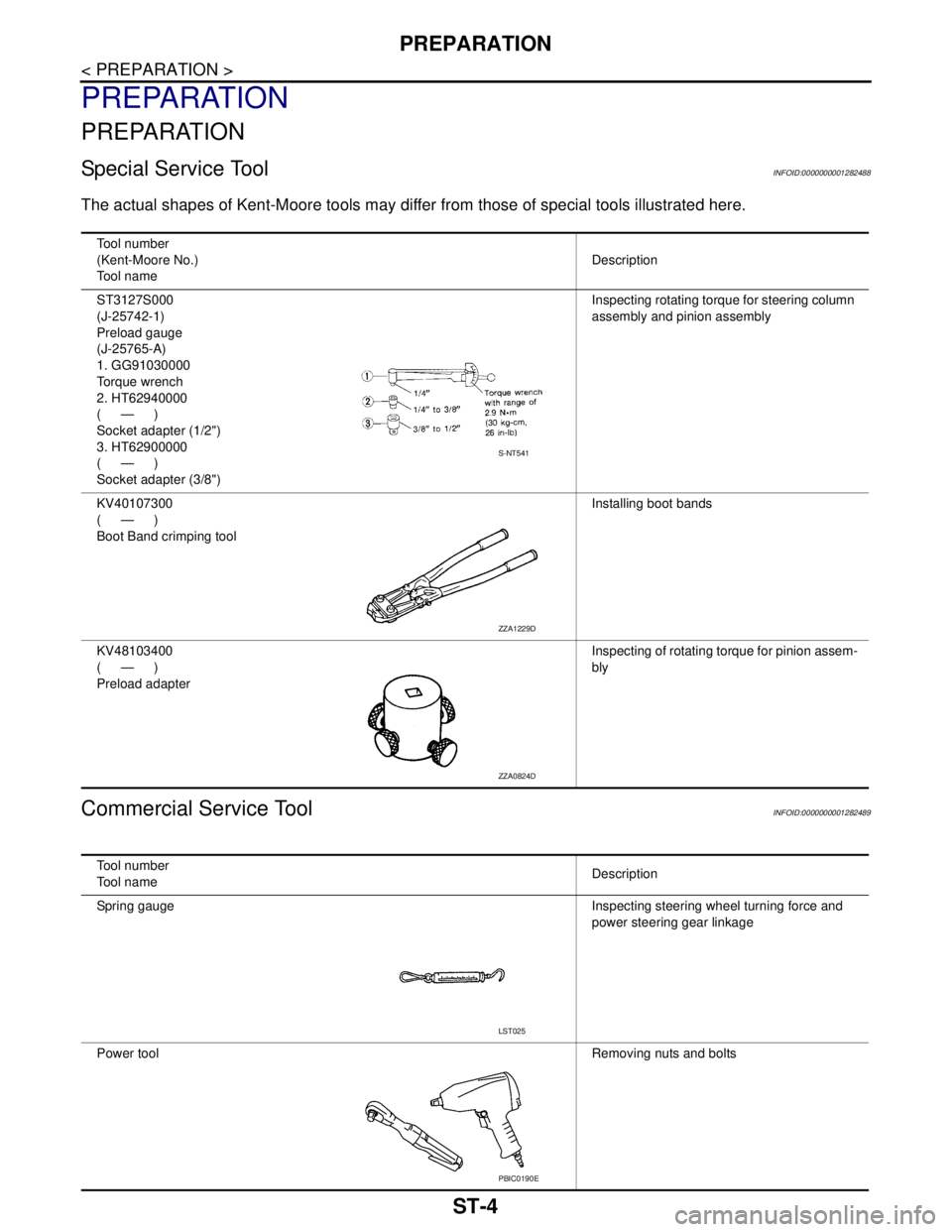
Special Service ToolINFOID:0000000001282488
The actual shapes of Kent-Moore tools may differ from those of special tools illustrated here.
Commercial Service ToolINFOID:0000000001282489
Tool number
(Kent-Moore No.)
Tool nameDescription
ST3127S000
(J-25742-1)
Preload gauge
(J-25765-A)
1. GG91030000
Torque wrench
2. HT62940000
(—)
Socket adapter (1/2")
3. HT62900000
(—)
Socket adapter (3/8")Inspecting rotating torque for steering column
assembly and pinion assembly
KV40107300
(—)
Boot Band crimping toolInstalling boot bands
KV48103400
(—)
Preload adapterInspecting of rotating torque for pinion assem-
bly
S-NT541
ZZA1229D
ZZA0824D
Tool number
Tool nameDescription
Spring gauge Inspecting steering wheel turning force and
power steering gear linkage
Power toolRemoving nuts and bolts
LST025
PBIC0190E