2007 NISSAN TIIDA light
[x] Cancel search: lightPage 3080 of 5883
BOTH SIDE FRONT FOG LAMPS ARE NOT TURNED ON
EXL-79
< SYMPTOM DIAGNOSIS >
C
D
E
F
G
H
I
J
K
MA
B
EXL
N
O
P
BOTH SIDE FRONT FOG LAMPS ARE NOT TURNED ON
DescriptionINFOID:0000000001523295
The front fog lamps do not turn ON in any setting.
Diagnosis ProcedureINFOID:0000000001523296
1.COMBINATION SWITCH INSPECTION
Check the combination switch. Refer to XX-XX, "*****"
.
Is the combination switch normal?
YES >> GO TO 2
NO >> Repair or replace the malfunctioning part.
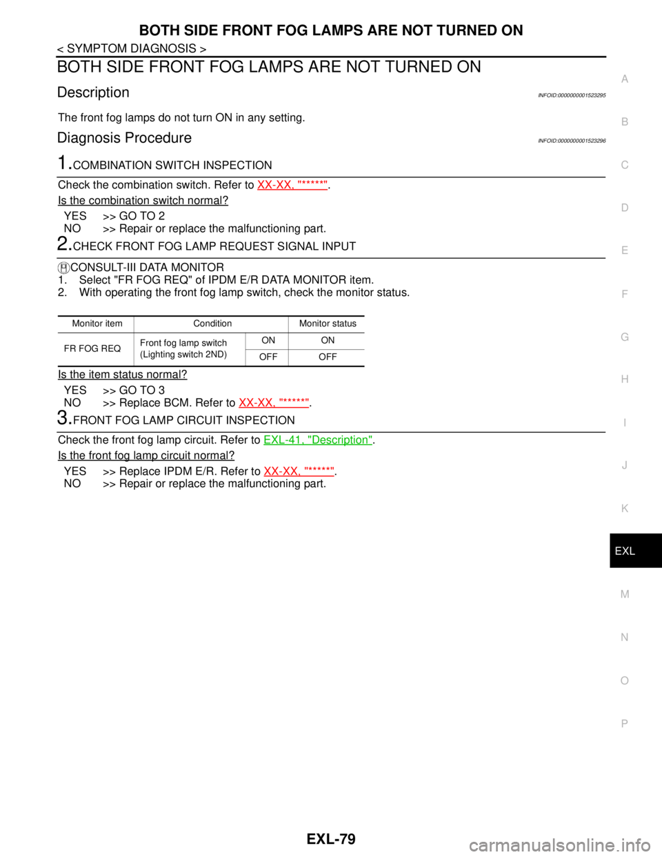
2.CHECK FRONT FOG LAMP REQUEST SIGNAL INPUT
CONSULT-III DATA MONITOR
1. Select "FR FOG REQ" of IPDM E/R DATA MONITOR item.
2. With operating the front fog lamp switch, check the monitor status.
Is the item status normal?
YES >> GO TO 3
NO >> Replace BCM. Refer to XX-XX, "*****"
.
3.FRONT FOG LAMP CIRCUIT INSPECTION
Check the front fog lamp circuit. Refer to EXL-41, "
Description".
Is the front fog lamp circuit normal?
YES >> Replace IPDM E/R. Refer to XX-XX, "*****".
NO >> Repair or replace the malfunctioning part.
Monitor item Condition Monitor status
FR FOG REQFront fog lamp switch
(Lighting switch 2ND)ON ON
OFF OFF
Page 3082 of 5883
HEADLAMP
EXL-81
< ON-VEHICLE MAINTENANCE >
C
D
E
F
G
H
I
J
K
MA
B
EXL
N
O
P
ON-VEHICLE MAINTENANCE
HEADLAMP
Aiming AdjustmentINFOID:0000000001529251
PREPARATION BEFORE ADJUSTING
Before performing aiming adjustment, check the following.
1. Keep all tires inflated to correct pressures.
2. Place vehicle on level surface.
3. Set that there is no-load in vehicle other than the driver (or equivalent weight placed in driver's position).
Coolant, engine oil filled up to correct level and full fuel tank.
LOW BEAM AND HIGH BEAM
1. Turn headlamp low beam ON.
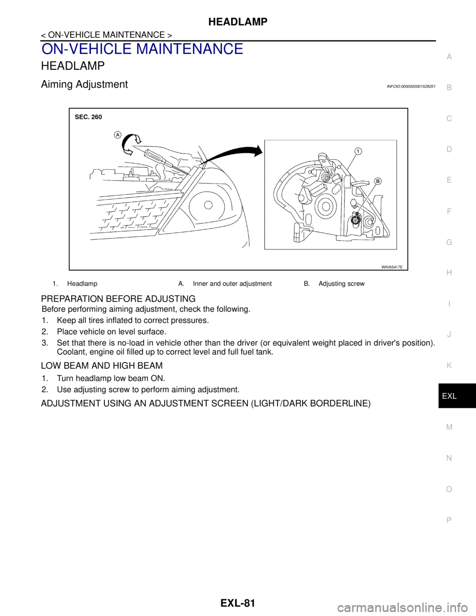
2. Use adjusting screw to perform aiming adjustment.
ADJUSTMENT USING AN ADJUSTMENT SCREEN (LIGHT/DARK BORDERLINE)
1. Headlamp A. Inner and outer adjustment B. Adjusting screw
WKIA5417E
Page 3085 of 5883
EXL-84
< ON-VEHICLE REPAIR >
HEADLAMP
ON-VEHICLE REPAIR
HEADLAMP
Bulb ReplacementINFOID:0000000001529252
HEADLAMP - HALOGEN (HIGH/LOW)
CAUTION:
After installing the halogen bulb, install the back cover and bulb socket securely to ensure a water
tight seal.
1. Turn lighting switch OFF.
2. Disconnect the battery negative terminal.
3. Remove the back cover.
4. Unlock the retaining spring and remove the bulb from the combination lamp.
HEADLAMP - XENON (HIGH/LOW)
CAUTION:
After installing the xenon bulb, install the plastic cap and bulb socket securely to ensure a water tight
seal.
1. Turn lighting switch OFF.
2. Disconnect the battery negative terminal.
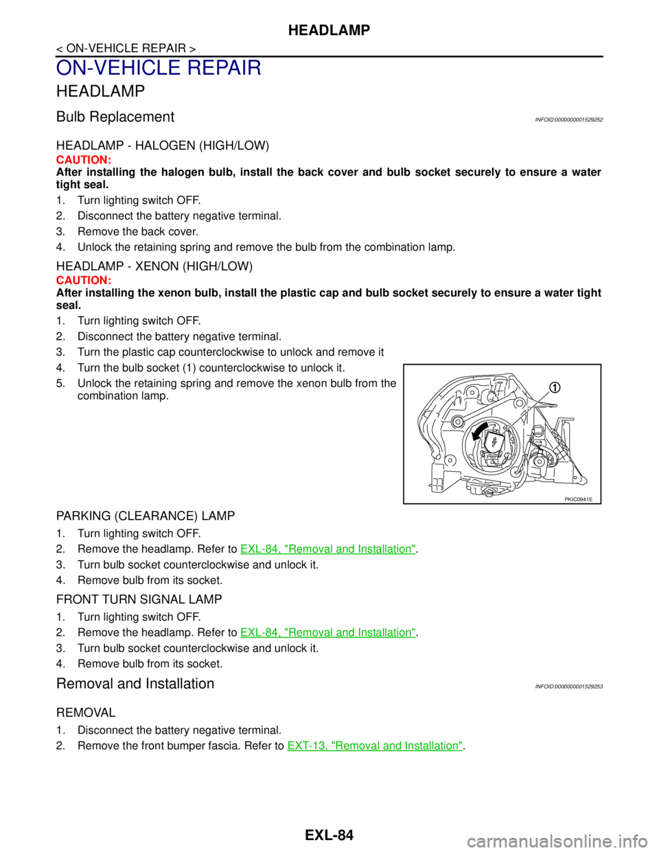
3. Turn the plastic cap counterclockwise to unlock and remove it
4. Turn the bulb socket (1) counterclockwise to unlock it.
5. Unlock the retaining spring and remove the xenon bulb from the
combination lamp.
PARKING (CLEARANCE) LAMP
1. Turn lighting switch OFF.
2. Remove the headlamp. Refer to EXL-84, "
Removal and Installation".
3. Turn bulb socket counterclockwise and unlock it.
4. Remove bulb from its socket.
FRONT TURN SIGNAL LAMP
1. Turn lighting switch OFF.
2. Remove the headlamp. Refer to EXL-84, "
Removal and Installation".
3. Turn bulb socket counterclockwise and unlock it.
4. Remove bulb from its socket.
Removal and InstallationINFOID:0000000001529253
REMOVAL
1. Disconnect the battery negative terminal.
2. Remove the front bumper fascia. Refer to EXT-13, "
Removal and Installation".
PKIC0941E
Page 3088 of 5883
FRONT FOG LAMP
EXL-87
< ON-VEHICLE REPAIR >
C
D
E
F
G
H
I
J
K
MA
B
EXL
N
O
P
FRONT FOG LAMP
Bulb ReplacementINFOID:0000000001529284
1. Turn the lighting switch OFF.
2. Reposition the fender protector (front) out of the way to access the front fog lamp.
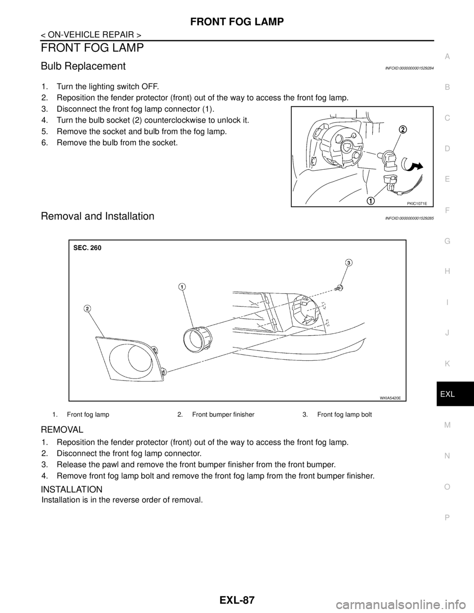
3. Disconnect the front fog lamp connector (1).
4. Turn the bulb socket (2) counterclockwise to unlock it.
5. Remove the socket and bulb from the fog lamp.
6. Remove the bulb from the socket.
Removal and InstallationINFOID:0000000001529285
REMOVAL
1. Reposition the fender protector (front) out of the way to access the front fog lamp.
2. Disconnect the front fog lamp connector.
3. Release the pawl and remove the front bumper finisher from the front bumper.
4. Remove front fog lamp bolt and remove the front fog lamp from the front bumper finisher.
INSTALLATION
Installation is in the reverse order of removal.
PKIC1071E
1. Front fog lamp 2. Front bumper finisher 3. Front fog lamp bolt
WKIA5420E
Page 3092 of 5883
AUTO LIGHT SYSTEM
EXL-91
< ON-VEHICLE REPAIR >
C
D
E
F
G
H
I
J
K
MA
B
EXL
N
O
P
AUTO LIGHT SYSTEM
Removal and Installation of Light and Rain SensorINFOID:0000000001530408
REMOVAL
1. Remove the rear view mirror. Refer to MIR-9, "Removal and Installation".
2. Disconnect the light and rain sensor connector.
3. Remove the light and rain sensor.
INSTALLATION
Installation is in the reverse order of removal.
Page 3102 of 5883
LIGHTING & TURN SIGNAL SWITCH
EXL-101
< ON-VEHICLE REPAIR >
C
D
E
F
G
H
I
J
K
MA
B
EXL
N
O
P
LIGHTING & TURN SIGNAL SWITCH
Removal and InstallationINFOID:0000000001529304
NOTE:
The lighting and turn signal switch is located on the LH side of the steering column for both the LHD and RHD
models.
REMOVAL
1. Remove the upper and lower steering column covers. Refer to IP-11, "Removal and Installation".
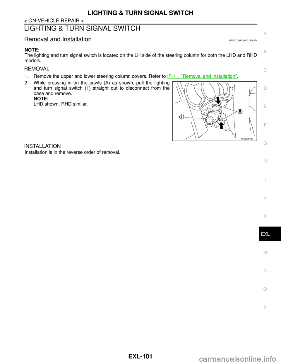
2. While pressing in on the pawls (A) as shown, pull the lighting
and turn signal switch (1) straight out to disconnect from the
base and remove.
NOTE:
LHD shown, RHD similar.
INSTALLATION
Installation is in the reverse order of removal.
PKIC1018E
Page 3108 of 5883
EXT-4
< ON-VEHICLE MAINTENANCE >
SQUEAK AND RATTLE TROUBLE DIAGNOSIS
ON-VEHICLE MAINTENANCE
SQUEAK AND RATTLE TROUBLE DIAGNOSIS
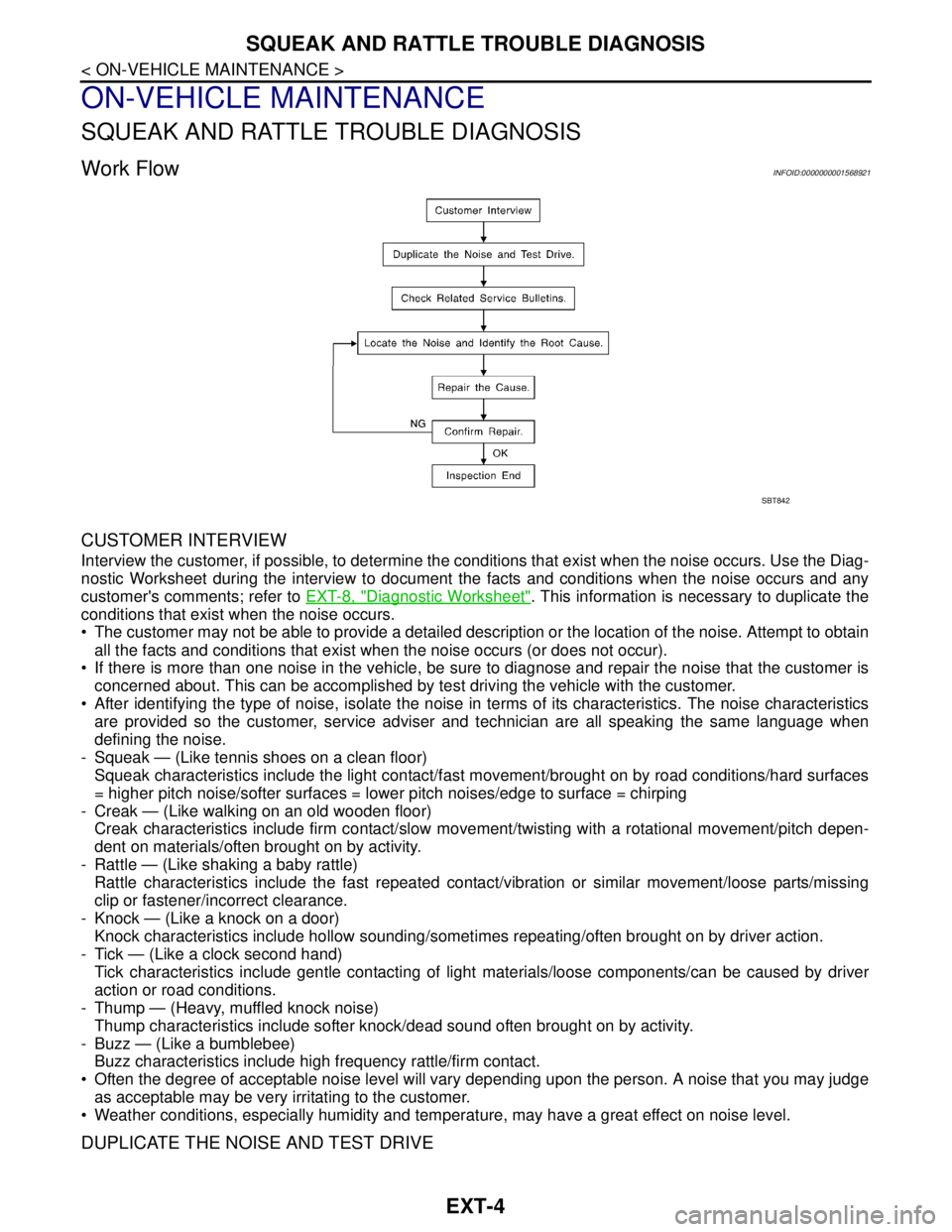
Work FlowINFOID:0000000001568921
CUSTOMER INTERVIEW
Interview the customer, if possible, to determine the conditions that exist when the noise occurs. Use the Diag-
nostic Worksheet during the interview to document the facts and conditions when the noise occurs and any
customer's comments; refer to EXT-8, "
Diagnostic Worksheet". This information is necessary to duplicate the
conditions that exist when the noise occurs.
The customer may not be able to provide a detailed description or the location of the noise. Attempt to obtain
all the facts and conditions that exist when the noise occurs (or does not occur).
If there is more than one noise in the vehicle, be sure to diagnose and repair the noise that the customer is
concerned about. This can be accomplished by test driving the vehicle with the customer.
After identifying the type of noise, isolate the noise in terms of its characteristics. The noise characteristics
are provided so the customer, service adviser and technician are all speaking the same language when
defining the noise.
- Squeak — (Like tennis shoes on a clean floor)
Squeak characteristics include the light contact/fast movement/brought on by road conditions/hard surfaces
= higher pitch noise/softer surfaces = lower pitch noises/edge to surface = chirping
- Creak — (Like walking on an old wooden floor)
Creak characteristics include firm contact/slow movement/twisting with a rotational movement/pitch depen-
dent on materials/often brought on by activity.
- Rattle — (Like shaking a baby rattle)
Rattle characteristics include the fast repeated contact/vibration or similar movement/loose parts/missing
clip or fastener/incorrect clearance.
- Knock — (Like a knock on a door)
Knock characteristics include hollow sounding/sometimes repeating/often brought on by driver action.
- Tick — (Like a clock second hand)
Tick characteristics include gentle contacting of light materials/loose components/can be caused by driver
action or road conditions.
- Thump — (Heavy, muffled knock noise)
Thump characteristics include softer knock/dead sound often brought on by activity.
- Buzz — (Like a bumblebee)
Buzz characteristics include high frequency rattle/firm contact.
Often the degree of acceptable noise level will vary depending upon the person. A noise that you may judge
as acceptable may be very irritating to the customer.
Weather conditions, especially humidity and temperature, may have a great effect on noise level.
DUPLICATE THE NOISE AND TEST DRIVE
SBT842
Page 3109 of 5883
SQUEAK AND RATTLE TROUBLE DIAGNOSIS
EXT-5
< ON-VEHICLE MAINTENANCE >
C
D
E
F
G
H
I
J
L
MA
B
EXT
N
O
P
If possible, drive the vehicle with the customer until the noise is duplicated. Note any additional information on
the Diagnostic Worksheet regarding the conditions or location of the noise. This information can be used to
duplicate the same conditions when you confirm the repair.
If the noise can be duplicated easily during the test drive, to help identify the source of the noise, try to dupli-
cate the noise with the vehicle stopped by doing one or all of the following:
Close a door.
Tap or push/pull around the area where the noise appears to be coming from.
Rev the engine.
Use a floor jack to recreate vehicle “twist”.
At idle, apply engine load (electrical load, half-clutch on M/T model, drive position on A/T model).
Raise the vehicle on a hoist and hit a tire with a rubber hammer.
Drive the vehicle and attempt to duplicate the conditions the customer states exist when the noise occurs.
If it is difficult to duplicate the noise, drive the vehicle slowly on an undulating or rough road to stress the
vehicle body.
CHECK RELATED SERVICE BULLETINS
After verifying the customer concern or symptom, check ASIST for Technical Service Bulletins (TSBs) related
to that concern or symptom.
If a TSB relates to the symptom, follow the procedure to repair the noise.
LOCATE THE NOISE AND IDENTIFY THE ROOT CAUSE
1. Narrow down the noise to a general area. To help pinpoint the source of the noise, use a listening tool
(Chassis Ear: J-39570, Engine Ear: J-39565 and mechanics stethoscope).
2. Narrow down the noise to a more specific area and identify the cause of the noise by:
Removing the components in the area that you suspect the noise is coming from.
Do not use too much force when removing clips and fasteners, otherwise clips and fasteners
can be broken or lost during the repair, resulting in the creation of new noise.
Tapping or pushing/pulling the component that you suspect is causing the noise.
Do not tap or push/pull the component with excessive force, otherwise the noise will be elimi-
nated only temporarily.
Feeling for a vibration with your hand by touching the component(s) that you suspect is (are) causing
the noise.
Placing a piece of paper between components that you suspect are causing the noise.
Looking for loose components and contact marks.
Refer to EXT-6, "
Generic Squeak and Rattle Troubleshooting".
REPAIR THE CAUSE
If the cause is a loose component, tighten the component securely.
If the cause is insufficient clearance between components:
- Separate components by repositioning or loosening and retightening the component, if possible.
- Insulate components with a suitable insulator such as urethane pads, foam blocks, felt cloth tape or ure-
thane tape. A Squeak and Rattle Kit is available through your authorized NISSAN Parts Department.
CAUTION:
Do not use excessive force as many components are constructed of plastic and may be damaged.
Always check with the Parts Department for the latest parts information.
The following materials are contained in the Squeak and Rattle Kit. Each item can be ordered separately as
needed.
URETHANE PADS [1.5 mm (0.059 in) thick]
Insulates connectors, harness, etc.
76268-9E005: 100 x 135 mm (3.94 x 5.31 in)/76884-71L01: 60 x 85 mm (2.36 x 3.35 in)/76884-71L02: 15 x 25
mm (0.59 x 0.98 in)
INSULATOR (Foam blocks)
Insulates components from contact. Can be used to fill space behind a panel.
73982-9E000: 45 mm (1.77 in) thick, 50 x 50 mm (1.97 x 1.97 in)/73982-50Y00: 10 mm (0.39 in) thick, 50 x 50
mm (1.97 x 1.97 in)
INSULATOR (Light foam block)
80845-71L00: 30 mm (1.18 in) thick, 30 x 50 mm (1.18 x 1.97 in)
FELT CLOTH TAPE
Used to insulate where movement does not occur. Ideal for instrument panel applications.
68370-4B000: 15 x 25 mm (0.59 x 0.98 in) pad/68239-13E00: 5 mm (0.20 in) wide tape roll
The following materials, not found in the kit, can also be used to repair squeaks and rattles.