2007 NISSAN TIIDA fuel pressure
[x] Cancel search: fuel pressurePage 3240 of 5883
GI-46
< PRECAUTION >
PRECAUTIONS
Precaution for Multiport Fuel Injection System or Engine Control System
INFOID:0000000001606121
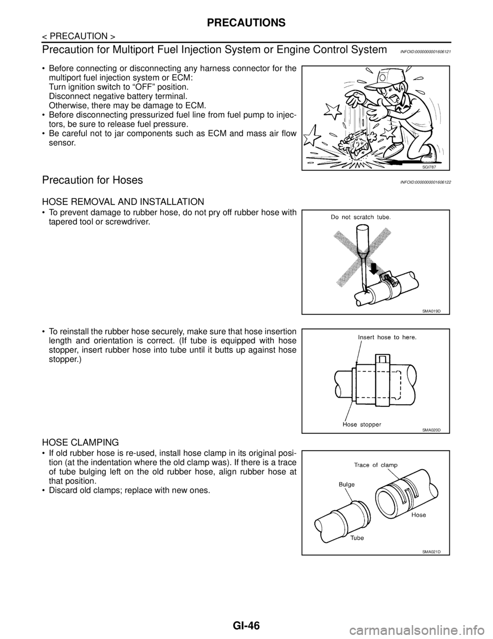
Before connecting or disconnecting any harness connector for the
multiport fuel injection system or ECM:
Turn ignition switch to “OFF” position.
Disconnect negative battery terminal.
Otherwise, there may be damage to ECM.
Before disconnecting pressurized fuel line from fuel pump to injec-
tors, be sure to release fuel pressure.
Be careful not to jar components such as ECM and mass air flow
sensor.
Precaution for HosesINFOID:0000000001606122
HOSE REMOVAL AND INSTALLATION
To prevent damage to rubber hose, do not pry off rubber hose with
tapered tool or screwdriver.
To reinstall the rubber hose securely, make sure that hose insertion
length and orientation is correct. (If tube is equipped with hose
stopper, insert rubber hose into tube until it butts up against hose
stopper.)
HOSE CLAMPING
If old rubber hose is re-used, install hose clamp in its original posi-
tion (at the indentation where the old clamp was). If there is a trace
of tube bulging left on the old rubber hose, align rubber hose at
that position.
Discard old clamps; replace with new ones.
SGI787
SMA019D
SMA020D
SMA021D
Page 4246 of 5883
MA-6
< ON-VEHICLE MAINTENANCE >
GENERAL MAINTENANCE
ON-VEHICLE MAINTENANCE
GENERAL MAINTENANCE
General MaintenanceINFOID:0000000001277597
General maintenance includes those items which should be checked during the normal day-to-day operation
of the vehicle. They are essential if the vehicle is to continue operating properly. The owners can perform the
checks and inspections themselves or they can have their NISSAN dealers do them for a nominal charge.
OUTSIDE THE VEHICLE
The maintenance items listed here should be performed from time to time, unless otherwise specified.
INSIDE THE VEHICLE
The maintenance items listed here should be checked on a regular basis, such as when performing periodic maintenance, cleaning the vehicle,
etc.
UNDER THE HOOD AND VEHICLE
The maintenance items listed here should be checked periodically e.g. each time you check the engine oil or refuel.
Item Reference page
TiresCheck the pressure with a gauge periodically when at a service station, including
the spare, and adjust to the specified pressure if necessary. Check carefully for
damage, cuts or excessive wear.WT-7, "
Tire"
Windshield wiper
bladesCheck for cracks or wear if not functioning correctly. —
Doors and engine
hoodCheck that all doors, the engine hood, the trunk lid and back door operate prop-
erly. Also ensure that all latches lock securely. Lubricate if necessary. Make sure
that the secondary latch keeps the hood from opening when the primary latch is
released.
When driving in areas using road salt or other corrosive materials, check for lu-
brication frequently.MA-57, "
Lubricating
Locks, Hinges and Hood
Latch"
Tire rotationTires should be rotated every 10,000 km (6,000 miles) for 2WD models and every
5,000 km (3,000 miles) for 4WD models.MA-53
Item Reference page
LampsMake sure that the headlamps, stop lamps, tail lamps, turn signal lamps, and oth-
er lamps are all operating properly and installed securely. Also check headlamp
aim.—
Warning lamps and
chimesMake sure that all warning lamps and buzzers/chimes are operating properly. —
Steering wheelCheck that it has the specified play.
Check for changes in the steering conditions, such as excessive free play, hard
steering or strange noises.
Free play: Less than 35 mm (1.38 in)—
Seat beltsCheck that all parts of the seat belt system (e.g. buckles, anchors, adjusters and
retractors) operate properly and smoothly, and are installed securely. Check the
belt webbing for cuts, fraying, wear or damage.MA-57
Item Reference page
Windshield washer
fluidCheck that there is adequate fluid in the tank. —
Engine coolant levelCheck the coolant level when the engine is cold.MA-23
(HR)
MA-31
(MR)
MA-42
(K9K)
Engine oil levelCheck the level after parking the vehicle on a level spot and turning off the en-
gine.LU-6
(HR)
LU-15
(MR)
LU-26
(K9K)
Brake and clutch fluid
levelsMake sure that the brake and clutch fluid levels are between the “MAX” and “MIN”
lines on the reservoir.MA-50
,
MA-54
BatteryCheck the fluid level in each cell. It should be between the “MAX” and “MIN” lines. —
Page 4274 of 5883
MA-34
< ON-VEHICLE MAINTENANCE >
ENGINE MAINTENANCE (MR18DE)
RADIATOR : Checking Radiator Cap
INFOID:0000000001730871
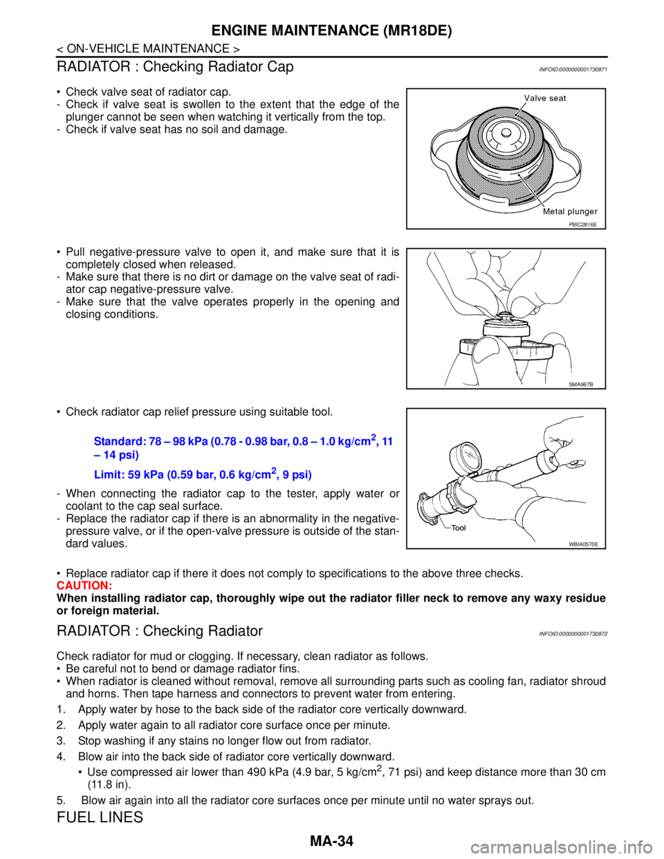
Check valve seat of radiator cap.
- Check if valve seat is swollen to the extent that the edge of the
plunger cannot be seen when watching it vertically from the top.
- Check if valve seat has no soil and damage.
Pull negative-pressure valve to open it, and make sure that it is
completely closed when released.
- Make sure that there is no dirt or damage on the valve seat of radi-
ator cap negative-pressure valve.
- Make sure that the valve operates properly in the opening and
closing conditions.
Check radiator cap relief pressure using suitable tool.
- When connecting the radiator cap to the tester, apply water or
coolant to the cap seal surface.
- Replace the radiator cap if there is an abnormality in the negative-
pressure valve, or if the open-valve pressure is outside of the stan-
dard values.
Replace radiator cap if there it does not comply to specifications to the above three checks.
CAUTION:
When installing radiator cap, thoroughly wipe out the radiator filler neck to remove any waxy residue
or foreign material.
RADIATOR : Checking RadiatorINFOID:0000000001730872
Check radiator for mud or clogging. If necessary, clean radiator as follows.
Be careful not to bend or damage radiator fins.
When radiator is cleaned without removal, remove all surrounding parts such as cooling fan, radiator shroud
and horns. Then tape harness and connectors to prevent water from entering.
1. Apply water by hose to the back side of the radiator core vertically downward.
2. Apply water again to all radiator core surface once per minute.
3. Stop washing if any stains no longer flow out from radiator.
4. Blow air into the back side of radiator core vertically downward.
Use compressed air lower than 490 kPa (4.9 bar, 5 kg/cm
2, 71 psi) and keep distance more than 30 cm
(11.8 in).
5. Blow air again into all the radiator core surfaces once per minute until no water sprays out.
FUEL LINES
PBIC2816E
SMA967B
Standard: 78 – 98 kPa (0.78 - 0.98 bar, 0.8 – 1.0 kg/cm2, 11
– 14 psi)
Limit: 59 kPa (0.59 bar, 0.6 kg/cm
2, 9 psi)
WBIA0570E
Page 4285 of 5883
ENGINE MAINTENANCE (K9K)
MA-45
< ON-VEHICLE MAINTENANCE >
C
D
E
F
G
H
I
J
K
L
MB
MAN
OA
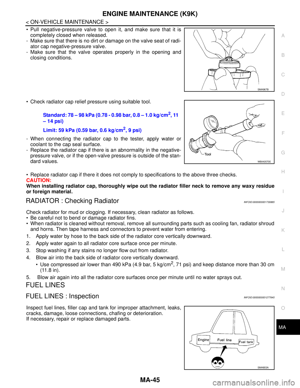
Pull negative-pressure valve to open it, and make sure that it is
completely closed when released.
- Make sure that there is no dirt or damage on the valve seat of radi-
ator cap negative-pressure valve.
- Make sure that the valve operates properly in the opening and
closing conditions.
Check radiator cap relief pressure using suitable tool.
- When connecting the radiator cap to the tester, apply water or
coolant to the cap seal surface.
- Replace the radiator cap if there is an abnormality in the negative-
pressure valve, or if the open-valve pressure is outside of the stan-
dard values.
Replace radiator cap if there it does not comply to specifications to the above three checks.
CAUTION:
When installing radiator cap, thoroughly wipe out the radiator filler neck to remove any waxy residue
or foreign material.
RADIATOR : Checking RadiatorINFOID:0000000001730885
Check radiator for mud or clogging. If necessary, clean radiator as follows.
Be careful not to bend or damage radiator fins.
When radiator is cleaned without removal, remove all surrounding parts such as cooling fan, radiator shroud
and horns. Then tape harness and connectors to prevent water from entering.
1. Apply water by hose to the back side of the radiator core vertically downward.
2. Apply water again to all radiator core surface once per minute.
3. Stop washing if any stains no longer flow out from radiator.
4. Blow air into the back side of radiator core vertically downward.
Use compressed air lower than 490 kPa (4.9 bar, 5 kg/cm
2, 71 psi) and keep distance more than 30 cm
(11.8 in).
5. Blow air again into all the radiator core surfaces once per minute until no water sprays out.
FUEL LINES
FUEL LINES : InspectionINFOID:0000000001277645
Inspect fuel lines, filler cap and tank for improper attachment, leaks,
cracks, damage, loose connections, chafing or deterioration.
If necessary, repair or replace damaged parts.
SMA967B
Standard: 78 – 98 kPa (0.78 - 0.98 bar, 0.8 – 1.0 kg/cm2, 11
– 14 psi)
Limit: 59 kPa (0.59 bar, 0.6 kg/cm
2, 9 psi)
WBIA0570E
SMA803A
Page 4309 of 5883

MWI-2
IPDM E/R (INTELLIGENT POWER DISTRIBU-
TION MODULE ENGINE ROOM) : Diagnosis Pro-
cedure .....................................................................
27
FUEL LEVEL SENSOR SIGNAL CIRCUIT .......29
Description ..............................................................29
Component Function Check ...................................29
Diagnosis Procedure .............................................29
Component Inspection ............................................30
OIL PRESSURE SWITCH SIGNAL CIRCUIT ...31
Description ..............................................................31
Component Function Check ...................................31
Diagnosis Procedure ..............................................31
Component Inspection ............................................31
OIL LEVEL SENSOR SIGNAL CIRCUIT ..........32
Description ..............................................................32
Diagnosis Procedure (With Diesel) .........................32
Diagnosis Procedure (Without Diesel) ....................32
Component Inspection (With Diesel) ......................32
Component Inspection (Without Diesel) .................33
AMBIENT SENSOR SIGNAL CIRCUIT .............34
Description ..............................................................34
Diagnosis Procedure ..............................................34
Component Inspection ............................................35
ECU DIAGNOSIS ........................................36
COMBINATION METER ....................................36
Reference Value .....................................................36
Wiring Diagram .......................................................39
Fail Safe .................................................................53
DTC Index ..............................................................54
BCM (BODY CONTROL MODULE) ..................55
Reference Value .....................................................55
Terminal Layout ......................................................58
Physical Values ......................................................58
Wiring Diagram .......................................................70
DTC Inspection Priority Chart ..............................73
DTC Index ..............................................................74
IPDM E/R (INTELLIGENT POWER DISTRI-
BUTION MODULE ENGINE ROOM) .................
75
Reference Value .....................................................75
Terminal Layout ......................................................77
Physical Values ......................................................77
Wiring Diagram .......................................................81
Fail Safe .................................................................84
DTC Index ..............................................................86
SYMPTOM DIAGNOSIS ............................87
THE FUEL GAUGE POINTER DOES NOT
MOVE .................................................................
87
Description ..............................................................87
Diagnosis Procedure ...............................................87
THE FUEL GAUGE POINTER DOES NOT
MOVE TO "F" WHEN REFUELING ..................
88
Description ..............................................................88
Diagnosis Procedure ...............................................88
THE OIL PRESSURE WARNING LAMP
DOES NOT TURN ON .......................................
89
Description ..............................................................89
Diagnosis Procedure ...............................................89
THE OIL PRESSURE WARNING LAMP
DOES NOT TURN OFF .....................................
90
Description ..............................................................90
Diagnosis Procedure ...............................................90
THE AMBIENT TEMPERATURE DISPLAY IS
INCORRECT ......................................................
91
Description ..............................................................91
Diagnosis Procedure ...............................................91
NORMAL OPERATING CONDITION ................92
INFORMATION DISPLAY .........................................92
INFORMATION DISPLAY : Description ..................92
PRECAUTION ............................................93
PRECAUTIONS .................................................93
Supplemental Restraint System (SRS) "AIR BAG"
and "SEAT BELT PRE-TENSIONER" ....................
93
ON-VEHICLE REPAIR ...............................94
COMBINATION METER ....................................94
Removal and Installation .........................................94
DISASSEMBLY AND ASSEMBLY ............97
COMBINATION METER ....................................97
Disassembly and Assembly ....................................97
Page 4313 of 5883
MWI-6
< FUNCTION DIAGNOSIS >
METER SYSTEM
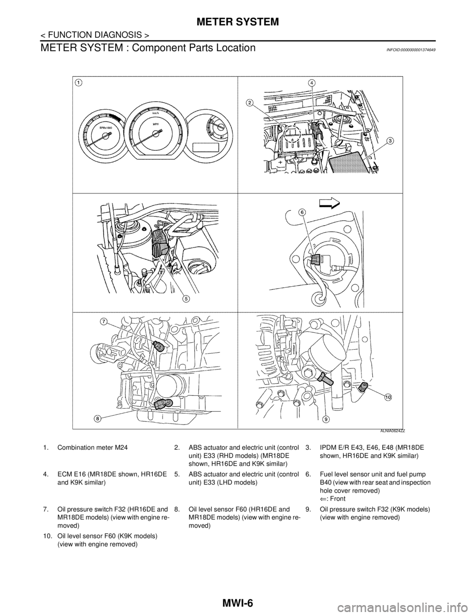
METER SYSTEM : Component Parts Location
INFOID:0000000001374649
1. Combination meter M24 2. ABS actuator and electric unit (control
unit) E33 (RHD models) (MR18DE
shown, HR16DE and K9K similar)3. IPDM E/R E43, E46, E48 (MR18DE
shown, HR16DE and K9K similar)
4. ECM E16 (MR18DE shown, HR16DE
and K9K similar)5. ABS actuator and electric unit (control
unit) E33 (LHD models)6. Fuel level sensor unit and fuel pump
B40 (view with rear seat and inspection
hole cover removed)
⇐: Front
7. Oil pressure switch F32 (HR16DE and
MR18DE models) (view with engine re-
moved)8. Oil level sensor F60 (HR16DE and
MR18DE models) (view with engine re-
moved)9. Oil pressure switch F32 (K9K models)
(view with engine removed)
10. Oil level sensor F60 (K9K models)
(view with engine removed)
ALNIA0624ZZ
Page 4314 of 5883
MWI
METER SYSTEM
MWI-7
< FUNCTION DIAGNOSIS >
C
D
E
F
G
H
I
J
K
L
MB A
O
P
METER SYSTEM : Component DescriptionINFOID:0000000001537306
SPEEDOMETER
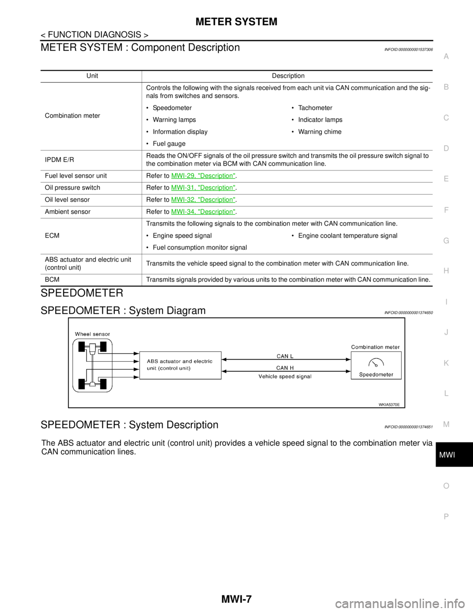
SPEEDOMETER : System DiagramINFOID:0000000001374650
SPEEDOMETER : System DescriptionINFOID:0000000001374651
The ABS actuator and electric unit (control unit) provides a vehicle speed signal to the combination meter via
CAN communication lines.
Unit Description
Combination meterControls the following with the signals received from each unit via CAN communication and the sig-
nals from switches and sensors.
Speedometer Tachometer
Warning lamps Indicator lamps
Information display Warning chime
Fuel gauge
IPDM E/RReads the ON/OFF signals of the oil pressure switch and transmits the oil pressure switch signal to
the combination meter via BCM with CAN communication line.
Fuel level sensor unit Refer to MWI-29, "
Description".
Oil pressure switch Refer to MWI-31, "
Description".
Oil level sensor Refer to MWI-32, "
Description".
Ambient sensor Refer to MWI-34, "
Description".
ECMTransmits the following signals to the combination meter with CAN communication line.
Engine speed signal Engine coolant temperature signal
Fuel consumption monitor signal
ABS actuator and electric unit
(control unit)Transmits the vehicle speed signal to the combination meter with CAN communication line.
BCM Transmits signals provided by various units to the combination meter with CAN communication line.
WKIA5370E
Page 4315 of 5883
MWI-8
< FUNCTION DIAGNOSIS >
METER SYSTEM
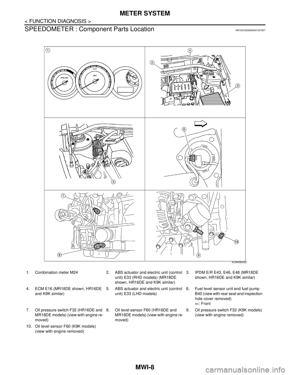
SPEEDOMETER : Component Parts Location
INFOID:0000000001537307
1. Combination meter M24 2. ABS actuator and electric unit (control
unit) E33 (RHD models) (MR18DE
shown, HR16DE and K9K similar)3. IPDM E/R E43, E46, E48 (MR18DE
shown, HR16DE and K9K similar)
4. ECM E16 (MR18DE shown, HR16DE
and K9K similar)5. ABS actuator and electric unit (control
unit) E33 (LHD models)6. Fuel level sensor unit and fuel pump
B40 (view with rear seat and inspection
hole cover removed)
⇐: Front
7. Oil pressure switch F32 (HR16DE and
MR18DE models) (view with engine re-
moved)8. Oil level sensor F60 (HR16DE and
MR18DE models) (view with engine re-
moved)9. Oil pressure switch F32 (K9K models)
(view with engine removed)
10. Oil level sensor F60 (K9K models)
(view with engine removed)
ALNIA0624ZZ