2007 NISSAN TIIDA tire pressure
[x] Cancel search: tire pressurePage 2397 of 5883
![NISSAN TIIDA 2007 Service Repair Manual EC-1048
< BASIC INSPECTION >[K9K]
INSPECTION AND ADJUSTMENT
>>INSPECTION END
BASIC INSPECTION : Special Repair Requirement (TEST 5: Rail High Pressure Reg-
ulation Check)
INFOID:0000000001162519
NOTE:](/manual-img/5/57395/w960_57395-2396.png "NISSAN TIIDA 2007 Service Repair Manual EC-1048
< BASIC INSPECTION >[K9K]
INSPECTION AND ADJUSTMENT
>>INSPECTION END
BASIC INSPECTION : Special Repair Requirement (TEST 5: Rail High Pressure Reg-
ulation Check)
INFOID:0000000001162519
NOTE:")
EC-1048
< BASIC INSPECTION >[K9K]
INSPECTION AND ADJUSTMENT
>>INSPECTION END
BASIC INSPECTION : Special Repair Requirement (TEST 5: Rail High Pressure Reg-
ulation Check)
INFOID:0000000001162519
NOTE:
If contaminants (swarf) can be seen in the transparent return pipe, the entire fuel injection system (fuel injec-
tors, pump, rail, high pressure pipes and all return pipes) must be replaced.
CONDITIONS PRIOR TO TEST
- Engine coolant temperature between 80 - 90°C (176 - 194°F).
- All the electrical load are switched off.
- Air conditioning is switched off.
- The tank is at least half-full.
- The pipe connections and unions have been checked.
- Check the sealing of the high pressure pipes and unions.
CAUSE
- Rail pressure variations around the setpoint.
- The rail reference pressure is not reached.
- Rough idle.
- Possibly noisy combustion.
1.CHECK AIR BUBBLES
1. Start engine
2. Are there large air bubbles in the transparent supply pipe going to the pump?
Is the inspection result normal?
YES >> Check low pressure system.
NO >> GO TO 2.
2.CHECK HIGH PRESSURE SUPPLY PUMP (VOLUMETRIC CONTROL VALVE)-I
Disconnect high pressure supply pump (volumetric control valve) harness connector.
Does the engine stop?
YES >> GO TO 3.
NO >> Replace high pressure supply pump (the high pressure supply pump [volumetric control valve]
remains open mechanically).
3.CHECK HIGH PRESSURE SUPPLY PUMP (PRESSURE CONTROL VALVE)-I
1. Reconnect high pressure supply pump (volumetric control valve) harness connector.
2. Turn ignition switch OFF and wait at least 30 seconds.
3. Start engine.
4. Disconnect high pressure supply pump (pressure control valve) harness connector.
Does the engine stop?
YES >> GO TO 4.
NO >> Replace high pressure supply pump (the high pressure supply pump [pressure control valve]
remains open mechanically).
4.CHECK FUEL INJECTOR
1. Reconnect high pressure supply pump (pressure control valve) harness connector.
2. Wait at least 30 seconds.
3. Start engine and let it idle speed.
4. Select “DATA MONITOR” mode with CONSULT-III.
5. Check that the “F/FLOW CORR CYL1”, “F/FLOW CORR CYL2”, “F/FLOW CORR CYL3”, “F/FLOW
CORR CYL4” indication.
Are the reference value 0.3 - 1.9?
YES >> GO TO 6.
NO >> GO TO 5.
5.CHECK MAJOR LEAK IN FUEL INJECTOR/FUEL INJECTORS OPEN
Carry out TEST 6.
Page 2401 of 5883
![NISSAN TIIDA 2007 Service Repair Manual EC-1052
< BASIC INSPECTION >[K9K]
INSPECTION AND ADJUSTMENT
2. Start engine and let it idle speed.
3. Select “DATA MONITOR” mode with CONSULT-III.
4. Check that the “RAIL PRESSURE” indication](/manual-img/5/57395/w960_57395-2400.png "NISSAN TIIDA 2007 Service Repair Manual EC-1052
< BASIC INSPECTION >[K9K]
INSPECTION AND ADJUSTMENT
2. Start engine and let it idle speed.
3. Select “DATA MONITOR” mode with CONSULT-III.
4. Check that the “RAIL PRESSURE” indication")
EC-1052
< BASIC INSPECTION >[K9K]
INSPECTION AND ADJUSTMENT
2. Start engine and let it idle speed.
3. Select “DATA MONITOR” mode with CONSULT-III.
4. Check that the “RAIL PRESSURE” indication under the following conditions.
NOTE:
An unusual combustion noise may be heard.
Is the inspection result normal?
YES >> GO TO 22.
NO >> GO TO 21.
21.CHECK FUEL RAIL PRESSURE-II
1. Turn ignition switch OFF.
2. Replace fuel rail. Refer to EM-281, "
Removal and Installation"
3. Start engine and let it idle speed.
4. Select “DATA MONITOR” mode with CONSULT-III.
5. Check that the “RAIL PRESSURE” indication under the following conditions.
NOTE:
An unusual combustion noise may be heard.
Is the inspection result normal?
YES >> GO TO 22.
NO >> Replace high pressure supply pump.
22.INSPECTION END
High pressure supply pump (volumetric control valve) OK.
>>INSPECTION END
BASIC INSPECTION : Special Repair Requirement (TEST 6: Major Leak in Fuel Injec-
tors/Fuel Injectors Open)
INFOID:0000000001162520
NOTE:
CONDITIONS PRIOR TO TEST
- The entire low pressure system must be in good condition.
- Check the sealing of the high pressure pipes and unions.
- Test 3 High pressure supply pump (pressure control valve) check is OK
- Test 4 High pressure supply pump (volumetric control valve) check is OK
- Test 5 Rail high pressure regulation circuit check is OK.
CAUSE
- Not enough or no rail pressure during starting.
- The engine does not start.
1.CHECK FUEL INJECTOR-I
Refer to EC-1141, "
Component Inspection".
Is the inspection result normal?
CONDITION (ENGINE SPEED) INDICATION
At idle speed 190 - 210 bar
2000 rpm 400 - 500 bar
3000 rpm 500 - 700 bar
4000 rpm 700 - 900 bar
CONDITION (ENGINE SPEED) INDICATION
At idle speed 190 - 210 bar
2000 rpm 400 - 500 bar
3000 rpm 500 - 700 bar
4000 rpm 700 - 900 bar
Page 2402 of 5883
![NISSAN TIIDA 2007 Service Repair Manual INSPECTION AND ADJUSTMENT
EC-1053
< BASIC INSPECTION >[K9K]
C
D
E
F
G
H
I
J
K
L
MA
EC
N
P O
YES >> GO TO 2.
NO >> Replace malfunctioning fuel injector.
2.CHECK INTERNAL FUEL TRANSFER PUMP
1. Turn igni](/manual-img/5/57395/w960_57395-2401.png "NISSAN TIIDA 2007 Service Repair Manual INSPECTION AND ADJUSTMENT
EC-1053
< BASIC INSPECTION >[K9K]
C
D
E
F
G
H
I
J
K
L
MA
EC
N
P O
YES >> GO TO 2.
NO >> Replace malfunctioning fuel injector.
2.CHECK INTERNAL FUEL TRANSFER PUMP
1. Turn igni")
INSPECTION AND ADJUSTMENT
EC-1053
< BASIC INSPECTION >[K9K]
C
D
E
F
G
H
I
J
K
L
MA
EC
N
P O
YES >> GO TO 2.
NO >> Replace malfunctioning fuel injector.
2.CHECK INTERNAL FUEL TRANSFER PUMP
1. Turn ignition switch OFF.
2. Disconnect the return system connections at the fuel injectors and close off the return pipes so they are
leak-tight.
3. To authorise a 15 second cranking engine and carry out this test it is essential to carry out the following
procedure:
- Disconnect high pressure supply pump (volumetric control valve) harness connector
- Turn ignition switch ON.
- Perform “SAVE DATA FOR CPU REPLC” in WORK SUPPORT mode with CONSULT-III.
- Perform “PRGRM REINITIALIZE” in WORK SUPPORT mode with CONSULT-III.
- Cranking engine for at least 15 seconds (starting speed 250 rpm)
- Perform “WRT DATA AFTR REPLC CPU” in WORK SUPPORT mode with CONSULT-III.
Is the return volume at the fuel injectors more than 20 ml per fuel injector for the starting phase?
NOTE:
Do not repeat this procedure more than 3 times and wait 30 seconds between each 15 second cranking
engine.
Then wait 30 minutes before cranking the engine for 3 15 second cycles.
Follow this instruction so that the starter does not get damaged.
Does the flow measure more than 20ml?
Yes >> Replace malfunctioning fuel injector.
No >> GO TO 3.
3.CHECK FUEL INJECTOR-II
1. Turn ignition switch OFF.
2. Reconnect return pipes.
3. Start Engine.
4. Select “DATA MONITOR” mode with CONSULT-III.
5. Check “RAIL PRESSURE” and “RAIL PRES SET” indication.
6. Does “RAIL PRESSURE” follow “RAIL PRES SET” during the 3 second cranking engine?
Is the inspection result normal?
YES >> GO TO 5.
NO >> GO TO 4.
4.CHECK GLOW PLUG
1. Turn ignition switch OFF.
2. Remove the glow plugs and check for moisture.
3. If the glow plugs are wet with fuel, it is possible that the fuel injector is leaking.
Are the glow plugs wet with fuel?
Yes >> Replace malfunction fuel injector.
No >> Replace high pressure supply pump.
5.INSPECTION END
Fuel injector system OK.
>>INSPECTION END
BASIC INSPECTION : Special Repair Requirement (TEST 7: Incorrect Fuel Injection
Quantity)
INFOID:0000000001162521
NOTE:
CONDITIONS PRIOR TO TEST
- The entire low pressure system must be in good condition.
- Check the sealing of the high pressure pipes and unions.
- Test 3 High pressure supply pump (pressure control valve) check is OK
- Test 4 High pressure supply pump (volumetric control valve) check is OK
- Test 5 Rail high pressure regulation circuit check is OK.
Page 2412 of 5883
![NISSAN TIIDA 2007 Service Repair Manual FUEL INJECTION CONTROL
EC-1063
< FUNCTION DIAGNOSIS >[K9K]
C
D
E
F
G
H
I
J
K
L
MA
EC
N
P O
FUEL INJECTION CONTROL
System DescriptionINFOID:0000000001162530
SYSTEM DESCRIPTION
The high pressure injecti](/manual-img/5/57395/w960_57395-2411.png "NISSAN TIIDA 2007 Service Repair Manual FUEL INJECTION CONTROL
EC-1063
< FUNCTION DIAGNOSIS >[K9K]
C
D
E
F
G
H
I
J
K
L
MA
EC
N
P O
FUEL INJECTION CONTROL
System DescriptionINFOID:0000000001162530
SYSTEM DESCRIPTION
The high pressure injecti")
FUEL INJECTION CONTROL
EC-1063
< FUNCTION DIAGNOSIS >[K9K]
C
D
E
F
G
H
I
J
K
L
MA
EC
N
P O
FUEL INJECTION CONTROL
System DescriptionINFOID:0000000001162530
SYSTEM DESCRIPTION
The high pressure injection system is designed to deliver a precise quantity of diesel fuel to the engine at a set
moment. The Siemens VDO piezo Common Rail system used on the K9K Step 2 engine is a second genera-
tion Common Rail injection system. Fuel pressure in the rail can reach a maximum of 1,600 bar. It uses fuel
injectors controlled by piezoelectric actuators. The fuel is pressurised by means of a high pressure pump then
sent to a rail which supplies the four fuel injectors.
The circuit comprises two subsystems, which are distinguished by the fuel pressure level:
- the low pressure circuit comprises the tank, the diesel fuel filter, the transfer pump and the fuel injector return
lines,
- the high-pressure circuit comprises the high-pressure (HP) pump, the rail, the fuel injectors and the high-
pressure (HP) pipes.
Finally, there are a number of control sensors and actuators which enable the entire system to be controlled
and monitored.
The system comprises:
- Priming bulb
- Fuel filter
- High pressure supply pump
- Fuel rail
- Fuel rail pressure sensor
- Fuel injector
- Fuel pump temperature sensor
- Engine coolant temperature sensor
- Camshaft position sensor
- Crankshaft position sensor
- Turbocharger boost sensor
- EGR volume control valve control position sensor
- EGR volume control valve
- Barometric pressure sensor (built in ECM)
- Mass air flow sensor
- Intake air temperature sensor
- Electric throttle control actuator
High Pressure Supply Pump
The high pressure supply pump consists of the following components:
Internal fuel transfer pump:
- This pump is a vane-type rotary pump. It draws in fuel from the fuel tank through a fuel filter and supplies the
high pressure pump with fuel.
Volumetric control valve:
- This solenoid valve regulates the flow of fuel entering the high pressure pump and enables an optimum
quantity of fuel to be pressurised according to operating phase; this improves the output of the high pressure
supply pump and thereby the output of the engine as well.
High pressure pump:
- This pump is a 3-piston radial pump, it generates the required pressure in the rail.
Pressure control valve:
- This solenoid valve regulates the output pressure of the high pressure pump.
Fuel Injector (Piezo Type)
CAUTION:
The fuel injector voltage is very high (much higher than that of conventional fuel injectors). This volt-
age can be as much as 150 V.
The piezo fuel injectors enable rapid, precise metering of the quantity of fuel injected, with excellent injection
process repetitivity.
The piezo actuator operates like a capacitor. To control the fuel injector, the computer sends, at the correct
time, a quantity of energy which is sufficient to enable the actuator to deform and the fuel injector to open.
During the injection period, the piezo actuator stores this energy.
At the end of the injection period, the computer recovers the energy sent at the start of the control operation.
The piezo actuator discharges and returns to its original shape. The fuel injector closes. To improve output, the
Page 2737 of 5883
![NISSAN TIIDA 2007 Service Repair Manual EM-90
< REMOVAL AND INSTALLATION >[HR16DE]
ENGINE ASSEMBLY
If items or work required are not covered by the engine section, follow the procedures in the applica-
ble sections.
Always use the suppo](/manual-img/5/57395/w960_57395-2736.png "NISSAN TIIDA 2007 Service Repair Manual EM-90
< REMOVAL AND INSTALLATION >[HR16DE]
ENGINE ASSEMBLY
If items or work required are not covered by the engine section, follow the procedures in the applica-
ble sections.
Always use the suppo")
EM-90
< REMOVAL AND INSTALLATION >[HR16DE]
ENGINE ASSEMBLY
If items or work required are not covered by the engine section, follow the procedures in the applica-
ble sections.
Always use the support point specified for lifting.
Use either 2-pole lift type or separate type lift as best you can. If board-on type is used for unavoid-
able reasons, support at the rear axle jacking point with a transmission jack or similar tool before
starting work, in preparation for the backward shift of center of gravity.
For supporting points for lifting and jacking point at rear axle, refer to GI-48, "
Garage Jack and
Safety Stand and 2-Pole Lift".
REMOVAL
Outline
Remove the engine and the transaxle assembly from the vehicle downward. Separate the engine and the tran-
saxle.
Preparation
1. Remove the hood assembly. Refer to DLK-214, "Removal and Installation".
2. Remove the cowl top cover and cowl top extension assembly. Refer to EXT-20, "
Removal and Installa-
tion".
3. Release fuel pressure. Refer to EC-377, "
Inspection" (EURO-OBD), EC-681, "Inspection" (WITHOUT
EURO-OBD).
4. Drain engine coolant from radiator. Refer to CO-11, "
Changing Engine Coolant".
CAUTION:
Perform this step when the engine is cold.
Never spill engine coolant on drive belt.
5. Drain the transmission fluid. Refer to TM-628, "
Draining" (M/T models), TM-171, "Changing A/T Fluid" (A/
T models).
6. Remove the following parts.
Engine undercover
Front road wheels and tires: Refer to WT-6, "
Rotation".
Front fender protector (RH and LH): Refer to EXT-22, "
Removal and Installation".
Battery and battery tray: Refer to PG-6, "
Removal and Installation".
Drive belt: Refer to EM-16, "
Removal and Installation".
Air duct and air cleaner case assembly: Refer to EM-27, "
Exploded View".
Radiator hose (upper and lower): Refer to CO-16, "
Component".
Disconnect cooling fan controller wiring harness.
Remove coolant reservoir tank.
Remove fan shroud and cooling fan assembly. Refer to CO-16, "
Component".
Engine Room LH
1. Disconnect all connections of engine harness around the engine mounting insulator (LH), and then tem-
porarily secure the engine harness into the engine side.
CAUTION:
Protect connectors using a resin bag against foreign materials.
2. Remove ground cable at transaxle side.
3. Disconnect fuel feed hose at engine side. Refer to EM-35, "
Exploded View".
4. Disconnect EVAP purge hose and brake booster vacuum hose.
5. Disconnect heater hoses, and install plugs them to prevent engine coolant from draining. Refer to CO-24,
"Exploded View".
6. Disconnect control linkage from transaxle. Refer to TM-189, "
Exploded View" (A/T), TM-630, "Exploded
View" (M/T).
7. Disconnect the clutch tube at transmission side. Refer to CL-12, "
Removal and Installation".
Engine Room RH
1. Remove ground cable between front cover and vehicle.
2. Remove generator and generator bracket; Refer to CHG-15, "
Removal and Installation".
3. Remove A/C compressor with piping connected from the engine. Temporarily secure it on the vehicle side
with a rope to avoid putting load on it. (with A/C models) Refer to HA-34, "
Removal and Installation of
Compressor - HR16DE".
Page 2885 of 5883
![NISSAN TIIDA 2007 Service Repair Manual EM-238
< SERVICE DATA AND SPECIFICATIONS (SDS) [MR18DE]
SERVICE DATA AND SPECIFICATIONS (SDS)
SERVICE DATA AND SPECIFICATIONS (SDS)
SERVICE DATA AND SPECIFICATIONS (SDS)
Standard and LimitINFOID:00000](/manual-img/5/57395/w960_57395-2884.png "NISSAN TIIDA 2007 Service Repair Manual EM-238
< SERVICE DATA AND SPECIFICATIONS (SDS) [MR18DE]
SERVICE DATA AND SPECIFICATIONS (SDS)
SERVICE DATA AND SPECIFICATIONS (SDS)
SERVICE DATA AND SPECIFICATIONS (SDS)
Standard and LimitINFOID:00000")
EM-238
< SERVICE DATA AND SPECIFICATIONS (SDS) [MR18DE]
SERVICE DATA AND SPECIFICATIONS (SDS)
SERVICE DATA AND SPECIFICATIONS (SDS)
SERVICE DATA AND SPECIFICATIONS (SDS)
Standard and LimitINFOID:0000000001337815
GENERAL SPECIFICATIONS
DRIVE BELT
WATER CONTROL VALVE
EXHAUST MANIFOLD
Unit: mm (in)
THERMOSTAT
SPARK PLUG
Unit: mm (in)
CYLINDER HEAD
Engine typeMR18DE
Cylinder arrangementIn-line 4
Displacement
cm
3 (cu in)1,798 (109.71)
Bore and stroke mm (in) 84.0 x 81.1 (3.307 x 3.192)
Valve arrangementDOHC
Firing order1-3-4-2
Number of piston ringsCompression 2
Oil 1
Compression ratio9.9
Compression pressure
kPa (bar, kg/cm
2 , psi) / 250 rpmStandard 1,500 (15.0, 15.3, 217.6)
Minimum 1,200 (12.0, 12.2, 174)
Differential limit between cylinders 100 (1.0, 1.0, 15)
Tension of drive belt Auto adjustment by auto-tensioner
Valve opening temperature 93.5 - 96.5°C (200 - 206°F)
Maximum valve lift 8 mm/ 108°C (0.315 in/ 226°F)
Valve closing temperature More than 90°C (194°F)
Items Limit
Surface distortionEach exhaust port 0.3 (0.012)
Entire part 0.7 (0.028)
Valve opening temperature 80.5 - 83.5°C (177 - 182°F)
Maximum valve lift 8 mm/ 95°C (0.315 in/ 203°F)
Valve closing temperature More than 77°C (171°F)
Plug typePlatinum-tipped TYPE
MakeNGK
Standard typePLZKAR6A-11
Spark plug gapNominal: 1.1 (0.043)
Page 2934 of 5883
![NISSAN TIIDA 2007 Service Repair Manual HIGH PRESSURE SUPPLY PUMP
EM-287
< ON-VEHICLE REPAIR >[K9K]
C
D
E
F
G
H
I
J
K
L
MA
EM
N
P O
HIGH PRESSURE SUPPLY PUMP
Exploded ViewINFOID:0000000001381495
Removal and InstallationINFOID:00000000013814](/manual-img/5/57395/w960_57395-2933.png "NISSAN TIIDA 2007 Service Repair Manual HIGH PRESSURE SUPPLY PUMP
EM-287
< ON-VEHICLE REPAIR >[K9K]
C
D
E
F
G
H
I
J
K
L
MA
EM
N
P O
HIGH PRESSURE SUPPLY PUMP
Exploded ViewINFOID:0000000001381495
Removal and InstallationINFOID:00000000013814")
HIGH PRESSURE SUPPLY PUMP
EM-287
< ON-VEHICLE REPAIR >[K9K]
C
D
E
F
G
H
I
J
K
L
MA
EM
N
P O
HIGH PRESSURE SUPPLY PUMP
Exploded ViewINFOID:0000000001381495
Removal and InstallationINFOID:0000000001381496
REMOVAL
CAUTION:
Be sure to read “Precautions for Diesel Equipment”. Refer to EM-253, "
Precaution for Diesel Equip-
ment".
Wait until the fuel temperature drops before carrying out any work.
Order the special high pressure injection circuit plug kit.
It is strictly forbidden to remove any high pressure supply
pump sprocket marked number 070 575 (see diagram). If the
pump is being replaced, the pulley must be replaced.
1. Disconnect the battery.
2. Remove air duct (inlet). Refer to EM-269, "
Exploded View".
3. Remove engine cover.
4. Remove blow-by hose.
5. Remove charge air cooler hose and pipes. Refer to EM-270,
"Exploded View".
6. Remove the RH front tire. Refer to WT-6, "
Rotation".
7. Remove fender protector (RH). Refer to EXT-22, "
Removal and
Installation".
8. Remove drive belt. Refer to EM-263, "
Removal and Installation".
9. Support the engine using suitable tool.
10. Remove the timing belt. Refer to EM-291, "
Removal and Installation".
11. Remove the oil level gauge guide and plug the hole. Refer to EM-281, "
Exploded View".
12. Remove high pressure pipes protection cover (upper). Refer to EM-281, "
Exploded View".
13. Carefully disconnect:
The connectors from the flow actuator,
The connectors from the fuel temperature sensor,
On the pump, the fuel supply and return pipes.
The return pipe connecting the injectors with the pump.
14. Remove the injection tube connecting the pump to the rail. Refer to EM-281, "
Removal and Installation".
1. High pressure supply pump protec-
tor2. Stud bolt 3. High pressure supply pump
4. Engine cover bracket
E1BIA0119GB
MBIB9036E
Page 3082 of 5883
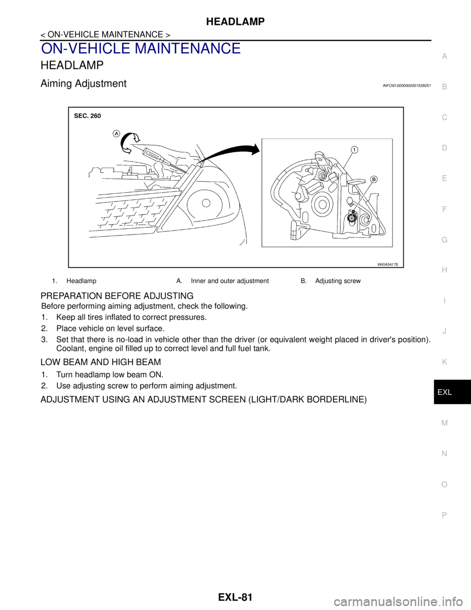
HEADLAMP
EXL-81
< ON-VEHICLE MAINTENANCE >
C
D
E
F
G
H
I
J
K
MA
B
EXL
N
O
P
ON-VEHICLE MAINTENANCE
HEADLAMP
Aiming AdjustmentINFOID:0000000001529251
PREPARATION BEFORE ADJUSTING
Before performing aiming adjustment, check the following.
1. Keep all tires inflated to correct pressures.
2. Place vehicle on level surface.
3. Set that there is no-load in vehicle other than the driver (or equivalent weight placed in driver's position).
Coolant, engine oil filled up to correct level and full fuel tank.
LOW BEAM AND HIGH BEAM
1. Turn headlamp low beam ON.
2. Use adjusting screw to perform aiming adjustment.
ADJUSTMENT USING AN ADJUSTMENT SCREEN (LIGHT/DARK BORDERLINE)
1. Headlamp A. Inner and outer adjustment B. Adjusting screw
WKIA5417E