2007 NISSAN TIIDA sensor
[x] Cancel search: sensorPage 1307 of 5883
![NISSAN TIIDA 2007 Service Repair Manual DLK-718
< SYMPTOM DIAGNOSIS >[WITHOUT I-KEY, WITH SUPER LOCK]
DOOR LOCK FUNCTION SYMPTOMS
SYMPTOM DIAGNOSIS
DOOR LOCK FUNCTION SYMPTOMS
DOOR LOCK AND UNLOCK SWITCH
DOOR LOCK AND UNLOCK SWITCH : Sympto NISSAN TIIDA 2007 Service Repair Manual DLK-718
< SYMPTOM DIAGNOSIS >[WITHOUT I-KEY, WITH SUPER LOCK]
DOOR LOCK FUNCTION SYMPTOMS
SYMPTOM DIAGNOSIS
DOOR LOCK FUNCTION SYMPTOMS
DOOR LOCK AND UNLOCK SWITCH
DOOR LOCK AND UNLOCK SWITCH : Sympto](/manual-img/5/57395/w960_57395-1306.png)
DLK-718
< SYMPTOM DIAGNOSIS >[WITHOUT I-KEY, WITH SUPER LOCK]
DOOR LOCK FUNCTION SYMPTOMS
SYMPTOM DIAGNOSIS
DOOR LOCK FUNCTION SYMPTOMS
DOOR LOCK AND UNLOCK SWITCH
DOOR LOCK AND UNLOCK SWITCH : Symptom TableINFOID:0000000001397332
DOOR LOCK AND UNLOCK SWITCH OPERATION MALFUNCTION
NOTE:
Before performing the diagnosis in the following table, check “Work Flow”. Refer to DLK-610, "
Work Flow".
Check that vehicle is under the condition shown in “Conditions of vehicle” before starting diagnosis, and
check each symptom.
If the following symptoms are detected, check systems shown in the “Diagnosis/service procedure” column
in this order.
Conditions of Vehicle (Operating Conditions)
Except driver side, doors are closed.
Doors are not locked by keyfob.
Symptom Table
KEYFOB
Symptom Diagnosis/service procedure Reference page
Power door lock does not operate with door lock
and unlock switch.1. BCM Power supply and ground circuit check.BCS-30
2. Door lock and unlock switch check.DLK-61
3. Door lock actuator (driver side) checkDLK-108
4. Intermittent Incident check. GI
Specific door lock actuator does not operate.1a. Driver side door lock actuator check.DLK-108
1b. Passenger side door lock actuator check.DLK-109
1c. Rear LH side door lock actuator check.D L K - 111
1d. Rear RH side door lock actuator check.DLK-113
1e. Back door lock actuator (hatchback) check.DLK-114
2. Intermittent Incident check. GI
Specific door does not open from inside the vehicle.1a. Driver side super lock actuator check.DLK-108
1b. Passenger side super lock actuator check.DLK-109
1c. Rear LH side super lock actuator check.D L K - 111
1d. Rear RH side super lock actuator check.DLK-113
2. Intermittent Incident check. GI
Instrument panel warning lamp indicator does not
operate.1. Instrument panel warning lamp assembly check.DLK-293
2. Intermittent Incident check. GI
Key reminder function does not operate properly.1.Check “ANTI KEY LOCK IN FUNCTION” setting in
“WORK SUPPORT”.DLK-50
2a. Driver side door switch check.DLK-65
2b. Passenger side door switch check.DLK-67
2c. Rear LH side door switch check.DLK-69
2d. Rear RH side door switch check.DLK-71
2e. Back door switch (hatchback) check.DLK-73
3. Front door lock actuator LH (door unlock sensor) check.DLK-104
4. Replace BCM.BCS-57
Page 1326 of 5883
![NISSAN TIIDA 2007 Service Repair Manual HOOD
DLK-737
< REMOVAL AND INSTALLATION >[WITHOUT I-KEY, WITH SUPER LOCK]
C
D
E
F
G
H
I
J
L
MA
B
DLK
N
O
P
RH Drive
REMOVAL
Hood Lock
1. Remove front grille (LH or RH as necessary). Refer to EXT-19, " NISSAN TIIDA 2007 Service Repair Manual HOOD
DLK-737
< REMOVAL AND INSTALLATION >[WITHOUT I-KEY, WITH SUPER LOCK]
C
D
E
F
G
H
I
J
L
MA
B
DLK
N
O
P
RH Drive
REMOVAL
Hood Lock
1. Remove front grille (LH or RH as necessary). Refer to EXT-19, "](/manual-img/5/57395/w960_57395-1325.png)
HOOD
DLK-737
< REMOVAL AND INSTALLATION >[WITHOUT I-KEY, WITH SUPER LOCK]
C
D
E
F
G
H
I
J
L
MA
B
DLK
N
O
P
RH Drive
REMOVAL
Hood Lock
1. Remove front grille (LH or RH as necessary). Refer to EXT-19, "Removal and Installation".
2. Remove hood lock bolts.
3. Remove hood lock from hood lock cable.
Hood Lock Reinforcement
1. Remove front bumper. Refer to EXT-15, "Removal and Installation - Hatchback" or EXT-17, "Removal and
Installation - Sedan".
2. Remove crash zone sensor.
3. Remove bolts, and the hood lock reinforcement.
Hood Lock Cable
1. Remove front grille (LH/RH). Refer to EXT-19, "Removal and Installation".
2. Remove fender protector (LH or RH as necessary). Refer to EXT-22, "
Removal and Installation".
3. Remove hood lock, and remove hood lock cable from hood lock.
4. Remove radiator core upper support, hood ledge, and then remove hood lock cable.
1. Hood lock 2. Hood lock cable 3. Hood ledge upper front
4. Clip
ALKIA0638GB
1. Hood lock 2. Hood lock cable 3. Hood ledge upper front
4. Clip
23.6 N·m (2.4 kg-m, 17 ft-lb)
23.6 N·m (2.4 kg-m, 17 ft-lb)
PIIB6511E
Page 1351 of 5883

EC-2
Component Parts Location ...................................63
Component Description .........................................68
CAN COMMUNICATION ...................................69
System Description .................................................69
COOLING FAN CONTROL ...............................70
System Diagram .....................................................70
System Description .................................................70
Component Parts Location ...................................72
Component Description ..........................................77
EVAPORATIVE EMISSION SYSTEM ...............78
System Diagram .....................................................78
System Description .................................................80
Component Parts Location ...................................81
Component Description .........................................86
INTAKE VALVE TIMING CONTROL .................87
System Diagram .....................................................87
System Description .................................................87
Component Parts Location ...................................88
Component Description ..........................................93
ON BOARD DIAGNOSTIC (OBD) SYSTEM .....94
Diagnosis Description .............................................94
CONSULT-III Function ..........................................107
Diagnosis Tool Function ......................................114
COMPONENT DIAGNOSIS .......................116
TROUBLE DIAGNOSIS - SPECIFICATION
VALUE .............................................................
116
Description .............................................................116
Component Function Check ..................................116
Diagnosis Procedure .............................................117
POWER SUPPLY AND GROUND CIRCUIT ...124
Diagnosis Procedure .............................................124
U1000, U1001 CAN COMM CIRCUIT .............128
Description .............................................................128
DTC Logic ..............................................................128
Diagnosis Procedure .............................................128
U1010 CONTROL UNIT (CAN) .......................129
Description .............................................................129
DTC Logic ..............................................................129
Diagnosis Procedure .............................................129
P0011 IVT CONTROL ......................................130
DTC Logic ..............................................................130
Diagnosis Procedure .............................................131
Component Inspection ...........................................132
P0102, P0103 MAF SENSOR ..........................134
Description .............................................................134
DTC Logic ..............................................................134
Diagnosis Procedure .............................................135
Component Inspection ...........................................136
P0112, P0113 IAT SENSOR ............................139
Description ............................................................139
DTC Logic .............................................................139
Diagnosis Procedure .............................................140
Component Inspection ..........................................140
P0117, P0118 ECT SENSOR ...........................142
Description ............................................................142
DTC Logic .............................................................142
Diagnosis Procedure .............................................143
Component Inspection ..........................................143
P0122, P0123 TP SENSOR ..............................145
Description ............................................................145
DTC Logic .............................................................145
Diagnosis Procedure .............................................145
Component Inspection ..........................................147
Special Repair Requirement .................................147
P0132 HO2S1 ...................................................148
Description ............................................................148
DTC Logic .............................................................148
Diagnosis Procedure .............................................149
Component Inspection ..........................................150
P0133 HO2S1 ...................................................152
Description ............................................................152
DTC Logic .............................................................152
Diagnosis Procedure .............................................154
Component Inspection ..........................................155
P0134 HO2S1 ...................................................158
Description ............................................................158
DTC Logic .............................................................158
Diagnosis Procedure .............................................159
Component Inspection ..........................................160
P0135 HO2S1 HEATER ...................................163
Description ............................................................163
DTC Logic .............................................................163
Diagnosis Procedure .............................................163
Component Inspection ..........................................164
P0138 HO2S2 ...................................................166
Description ............................................................166
DTC Logic .............................................................166
Diagnosis Procedure .............................................167
Component Inspection ..........................................168
P0139 HO2S2 ...................................................170
Description ............................................................170
DTC Logic .............................................................170
Component Function Check .................................172
Diagnosis Procedure .............................................173
Component Inspection ..........................................174
P0141 HO2S2 HEATER ...................................176
Description ............................................................176
DTC Logic .............................................................176
Diagnosis Procedure .............................................176
Component Inspection ..........................................178
Page 1352 of 5883

EC-3
C
D
E
F
G
H
I
J
K
L
M
ECA
N
O
P
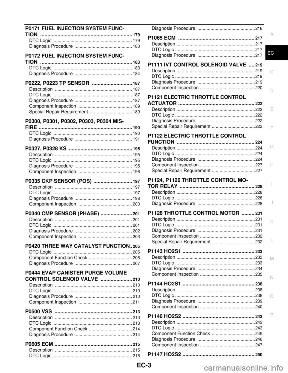
P0171 FUEL INJECTION SYSTEM FUNC-
TION .................................................................
179
DTC Logic .............................................................179
Diagnosis Procedure .............................................180
P0172 FUEL INJECTION SYSTEM FUNC-
TION .................................................................
183
DTC Logic .............................................................183
Diagnosis Procedure .............................................184
P0222, P0223 TP SENSOR .............................187
Description ............................................................187
DTC Logic .............................................................187
Diagnosis Procedure .............................................187
Component Inspection ..........................................189
Special Repair Requirement .................................189
P0300, P0301, P0302, P0303, P0304 MIS-
FIRE ..................................................................
190
DTC Logic .............................................................190
Diagnosis Procedure .............................................191
P0327, P0328 KS .............................................195
Description ............................................................195
DTC Logic .............................................................195
Diagnosis Procedure .............................................195
Component Inspection ..........................................196
P0335 CKP SENSOR (POS) ............................197
Description ............................................................197
DTC Logic .............................................................197
Diagnosis Procedure .............................................198
Component Inspection ..........................................200
P0340 CMP SENSOR (PHASE) .......................201
Description ............................................................201
DTC Logic .............................................................201
Diagnosis Procedure .............................................202
Component Inspection ..........................................203
P0420 THREE WAY CATALYST FUNCTION ..205
DTC Logic .............................................................205
Component Function Check ..................................206
Diagnosis Procedure .............................................207
P0444 EVAP CANISTER PURGE VOLUME
CONTROL SOLENOID VALVE .......................
210
Description ............................................................210
DTC Logic .............................................................210
Diagnosis Procedure .............................................210
Component Inspection ..........................................211
P0500 VSS .......................................................213
Description ............................................................213
DTC Logic .............................................................213
Component Function Check ..................................214
Diagnosis Procedure .............................................214
P0605 ECM .......................................................215
Description ............................................................215
DTC Logic .............................................................215
Diagnosis Procedure .............................................216
P1065 ECM .....................................................217
Description .............................................................217
DTC Logic ..............................................................217
Diagnosis Procedure .............................................217
P1111 IVT CONTROL SOLENOID VALVE ....219
Description .............................................................219
DTC Logic ..............................................................219
Diagnosis Procedure .............................................219
Component Inspection ...........................................220
P1121 ELECTRIC THROTTLE CONTROL
ACTUATOR .....................................................
222
Description .............................................................222
DTC Logic ..............................................................222
Diagnosis Procedure .............................................222
Special Repair Requirement ..................................223
P1122 ELECTRIC THROTTLE CONTROL
FUNCTION ......................................................
224
Description .............................................................224
DTC Logic ..............................................................224
Diagnosis Procedure .............................................224
Component Inspection ...........................................227
Special Repair Requirement ..................................227
P1124, P1126 THROTTLE CONTROL MO-
TOR RELAY ....................................................
228
Description .............................................................228
DTC Logic ..............................................................228
Diagnosis Procedure .............................................228
P1128 THROTTLE CONTROL MOTOR .........231
Description .............................................................231
DTC Logic ..............................................................231
Diagnosis Procedure .............................................231
Component Inspection ...........................................232
Special Repair Requirement ..................................232
P1143 HO2S1 ..................................................233
Description .............................................................233
DTC Logic ..............................................................233
Diagnosis Procedure .............................................234
Component Inspection ...........................................235
P1144 HO2S1 ..................................................238
Description .............................................................238
DTC Logic ..............................................................238
Diagnosis Procedure .............................................239
Component Inspection ...........................................240
P1146 HO2S2 ..................................................243
Description .............................................................243
DTC Logic ..............................................................243
Component Function Check ..................................245
Diagnosis Procedure .............................................246
Component Inspection ...........................................247
P1147 HO2S2 ..................................................250
Page 1353 of 5883

EC-4
Description .............................................................250
DTC Logic ..............................................................250
Component Function Check ..................................252
Diagnosis Procedure .............................................253
Component Inspection ...........................................254
P1212 TCS COMMUNICATION LINE .............256
Description .............................................................256
DTC Logic ..............................................................256
Diagnosis Procedure .............................................256
P1217 ENGINE OVER TEMPERATURE .........257
DTC Logic ..............................................................257
Component Function Check ..................................257
Diagnosis Procedure .............................................258
P1225 TP SENSOR .........................................261
Description .............................................................261
DTC Logic ..............................................................261
Diagnosis Procedure .............................................261
Special Repair Requirement ..................................262
P1226 TP SENSOR .........................................263
Description .............................................................263
DTC Logic ..............................................................263
Diagnosis Procedure .............................................263
Special Repair Requirement ..................................264
P1229 SENSOR POWER SUPPLY .................265
DTC Logic ..............................................................265
Diagnosis Procedure .............................................265
P1564 ASCD STEERING SWITCH .................267
Description .............................................................267
DTC Logic ..............................................................267
Diagnosis Procedure .............................................267
Component Inspection ...........................................269
P1572 ASCD BRAKE SWITCH .......................270
Description .............................................................270
DTC Logic ..............................................................270
Diagnosis Procedure .............................................271
Component Inspection (ASCD Brake Switch) .......275
Component Inspection (ASCD Clutch Switch) .......276
Component Inspection (Stop Lamp Switch) ..........276
P1574 ASCD VEHICLE SPEED SENSOR ......278
Description .............................................................278
DTC Logic ..............................................................278
Diagnosis Procedure .............................................278
P1706 PNP SWITCH .......................................280
Description .............................................................280
DTC Logic ..............................................................280
Component Function Check ..................................281
Diagnosis Procedure .............................................281
P1805 BRAKE SWITCH ..................................283
Description .............................................................283
DTC Logic ..............................................................283
Diagnosis Procedure .............................................283
Component Inspection (Stop Lamp Switch) ..........284
P2122, P2123 APP SENSOR ...........................286
Description ............................................................286
DTC Logic .............................................................286
Diagnosis Procedure .............................................286
Component Inspection ..........................................288
Special Repair Requirement .................................288
P2127, P2128 APP SENSOR ...........................290
Description ............................................................290
DTC Logic .............................................................290
Diagnosis Procedure .............................................290
Component Inspection ..........................................293
Special Repair Requirement .................................293
P2135 TP SENSOR ..........................................294
Description ............................................................294
DTC Logic .............................................................294
Diagnosis Procedure .............................................294
Component Inspection ..........................................296
Special Repair Requirement .................................296
P2138 APP SENSOR .......................................297
Description ............................................................297
DTC Logic .............................................................297
Diagnosis Procedure .............................................297
Component Inspection ..........................................300
Special Repair Requirement .................................300
ASCD BRAKE SWITCH ...................................302
Description ............................................................302
Component Function Check .................................302
Diagnosis Procedure .............................................302
Component Inspection (ASCD Brake Switch) .......305
Component Inspection (ASCD Clutch Switch) ......305
ASCD INDICATOR ...........................................306
Description ............................................................306
Component Function Check .................................306
Diagnosis Procedure .............................................306
COOLING FAN .................................................307
Description ............................................................307
Component Function Check .................................307
Diagnosis Procedure .............................................307
Component Inspection ..........................................309
ELECTRICAL LOAD SIGNAL ..........................311
Description ............................................................311
Component Function Check .................................311
Diagnosis Procedure .............................................311
FUEL INJECTOR ..............................................313
Description ............................................................313
Component Function Check .................................313
Diagnosis Procedure .............................................313
Component Inspection ..........................................314
FUEL PUMP .....................................................316
Description ............................................................316
Page 1354 of 5883

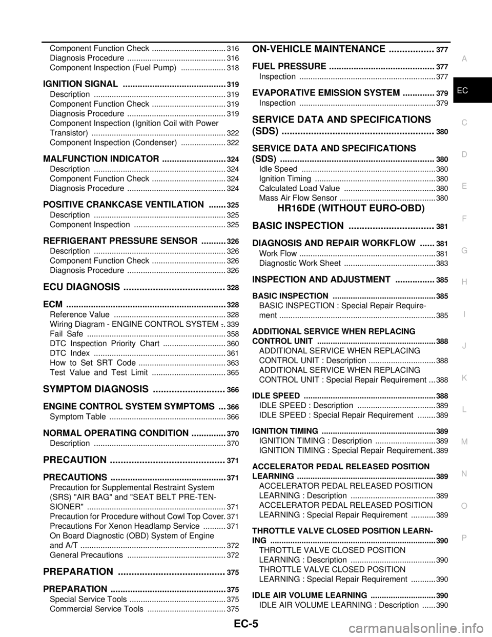
EC-5
C
D
E
F
G
H
I
J
K
L
M
ECA
N
O
P Component Function Check ..................................
316
Diagnosis Procedure .............................................316
Component Inspection (Fuel Pump) .....................318
IGNITION SIGNAL ...........................................319
Description ............................................................319
Component Function Check ..................................319
Diagnosis Procedure .............................................319
Component Inspection (Ignition Coil with Power
Transistor) .............................................................
322
Component Inspection (Condenser) .....................322
MALFUNCTION INDICATOR ...........................324
Description ............................................................324
Component Function Check ..................................324
Diagnosis Procedure .............................................324
POSITIVE CRANKCASE VENTILATION ........325
Description ............................................................325
Component Inspection ..........................................325
REFRIGERANT PRESSURE SENSOR ...........326
Description ............................................................326
Component Function Check ..................................326
Diagnosis Procedure .............................................326
ECU DIAGNOSIS .......................................328
ECM ..................................................................328
Reference Value ...................................................328
Wiring Diagram - ENGINE CONTROL SYSTEM - ..339
Fail Safe ...............................................................358
DTC Inspection Priority Chart .............................360
DTC Index ............................................................361
How to Set SRT Code ........................................363
Test Value and Test Limit ..................................365
SYMPTOM DIAGNOSIS ............................366
ENGINE CONTROL SYSTEM SYMPTOMS ....366
Symptom Table .....................................................366
NORMAL OPERATING CONDITION ...............370
Description ............................................................370
PRECAUTION ............................................371
PRECAUTIONS ................................................371
Precaution for Supplemental Restraint System
(SRS) "AIR BAG" and "SEAT BELT PRE-TEN-
SIONER" ...............................................................
371
Precaution for Procedure without Cowl Top Cover ..371
Precautions For Xenon Headlamp Service ...........371
On Board Diagnostic (OBD) System of Engine
and A/T ..................................................................
372
General Precautions .............................................372
PREPARATION .........................................375
PREPARATION ................................................375
Special Service Tools ............................................375
Commercial Service Tools ....................................375
ON-VEHICLE MAINTENANCE ..................377
FUEL PRESSURE ...........................................377
Inspection ..............................................................377
EVAPORATIVE EMISSION SYSTEM .............379
Inspection ..............................................................379
SERVICE DATA AND SPECIFICATIONS
(SDS) ..........................................................
380
SERVICE DATA AND SPECIFICATIONS
(SDS) ...............................................................
380
Idle Speed .............................................................380
Ignition Timing .......................................................380
Calculated Load Value ..........................................380
Mass Air Flow Sensor ............................................380
HR16DE (WITHOUT EURO-OBD)
BASIC INSPECTION .................................
381
DIAGNOSIS AND REPAIR WORKFLOW ......381
Work Flow ..............................................................381
Diagnostic Work Sheet ..........................................383
INSPECTION AND ADJUSTMENT ................385
BASIC INSPECTION ...............................................385
BASIC INSPECTION : Special Repair Require-
ment .......................................................................
385
ADDITIONAL SERVICE WHEN REPLACING
CONTROL UNIT ......................................................
388
ADDITIONAL SERVICE WHEN REPLACING
CONTROL UNIT : Description ...............................
388
ADDITIONAL SERVICE WHEN REPLACING
CONTROL UNIT : Special Repair Requirement ....
388
IDLE SPEED ............................................................388
IDLE SPEED : Description ....................................389
IDLE SPEED : Special Repair Requirement .........389
IGNITION TIMING ....................................................389
IGNITION TIMING : Description ............................389
IGNITION TIMING : Special Repair Requirement ..389
ACCELERATOR PEDAL RELEASED POSITION
LEARNING ...............................................................
389
ACCELERATOR PEDAL RELEASED POSITION
LEARNING : Description .......................................
389
ACCELERATOR PEDAL RELEASED POSITION
LEARNING : Special Repair Requirement ............
389
THROTTLE VALVE CLOSED POSITION LEARN-
ING ...........................................................................
390
THROTTLE VALVE CLOSED POSITION
LEARNING : Description .......................................
390
THROTTLE VALVE CLOSED POSITION
LEARNING : Special Repair Requirement ............
390
IDLE AIR VOLUME LEARNING ..............................390
IDLE AIR VOLUME LEARNING : Description .......390
Page 1355 of 5883

EC-6
IDLE AIR VOLUME LEARNING : Special Repair
Requirement ..........................................................
390
MIXTURE RATIO SELF-LEARNING VALUE
CLEAR .....................................................................
392
MIXTURE RATIO SELF-LEARNING VALUE
CLEAR : Description ..............................................
392
MIXTURE RATIO SELF-LEARNING VALUE
CLEAR : Special Repair Requirement ...................
392
FUNCTION DIAGNOSIS ............................393
ENGINE CONTROL SYSTEM .........................393
System Diagram ...................................................393
System Description ................................................394
Component Parts Location ..................................394
Component Description .........................................399
MULTIPORT FUEL INJECTION SYSTEM ......401
System Diagram ...................................................401
System Description ................................................401
Component Parts Location ..................................404
Component Description .........................................409
ELECTRIC IGNITION SYSTEM .......................410
System Diagram ...................................................410
System Description ................................................410
Component Parts Location ..................................411
Component Description .........................................416
AIR CONDITIONING CUT CONTROL ............417
System Diagram ....................................................417
System Description ................................................417
Component Parts Location ..................................418
Component Description .........................................423
AUTOMATIC SPEED CONTROL DEVICE
(ASCD) .............................................................
424
System Diagram ....................................................424
System Description ................................................424
Component Parts Location ..................................426
Component Description ........................................431
CAN COMMUNICATION .................................432
System Description ................................................432
COOLING FAN CONTROL .............................433
System Diagram ....................................................433
System Description ................................................433
Component Parts Location ..................................435
Component Description .........................................440
EVAPORATIVE EMISSION SYSTEM .............441
System Diagram ....................................................441
System Description ................................................443
Component Parts Location ..................................444
Component Description ........................................449
INTAKE VALVE TIMING CONTROL ...............450
System Diagram ....................................................450
System Description ................................................450
Component Parts Location ..................................451
Component Description ........................................456
DIAGNOSIS SYSTEM (ECM) ...........................457
Diagnosis Description ...........................................457
CONSULT-III Function ..........................................462
COMPONENT DIAGNOSIS ......................469
TROUBLE DIAGNOSIS - SPECIFICATION
VALUE ..............................................................
469
Description ............................................................469
Component Function Check .................................469
Diagnosis Procedure .............................................470
POWER SUPPLY AND GROUND CIRCUIT ....477
Diagnosis Procedure .............................................477
U1000, U1001 CAN COMM CIRCUIT ..............481
Description ............................................................481
DTC Logic .............................................................481
Diagnosis Procedure .............................................481
U1010 CONTROL UNIT (CAN) ........................482
Description ............................................................482
DTC Logic .............................................................482
Diagnosis Procedure .............................................482
P0011 IVT CONTROL ......................................483
DTC Logic .............................................................483
Component Function Check .................................484
Diagnosis Procedure .............................................484
Component Inspection ..........................................486
P0102, P0103 MAF SENSOR ..........................487
Description ............................................................487
DTC Logic .............................................................487
Diagnosis Procedure .............................................488
Component Inspection ..........................................489
P0117, P0118 ECT SENSOR ...........................492
Description ............................................................492
DTC Logic .............................................................492
Diagnosis Procedure .............................................493
Component Inspection ..........................................493
P0122, P0123 TP SENSOR ..............................495
Description ............................................................495
DTC Logic .............................................................495
Diagnosis Procedure .............................................495
Component Inspection ..........................................497
Special Repair Requirement .................................497
P0132 HO2S1 ...................................................498
Description ............................................................498
DTC Logic .............................................................498
Diagnosis Procedure .............................................499
Component Inspection ..........................................500
P0134 HO2S1 ...................................................502
Description ............................................................502
DTC Logic .............................................................502
Page 1356 of 5883

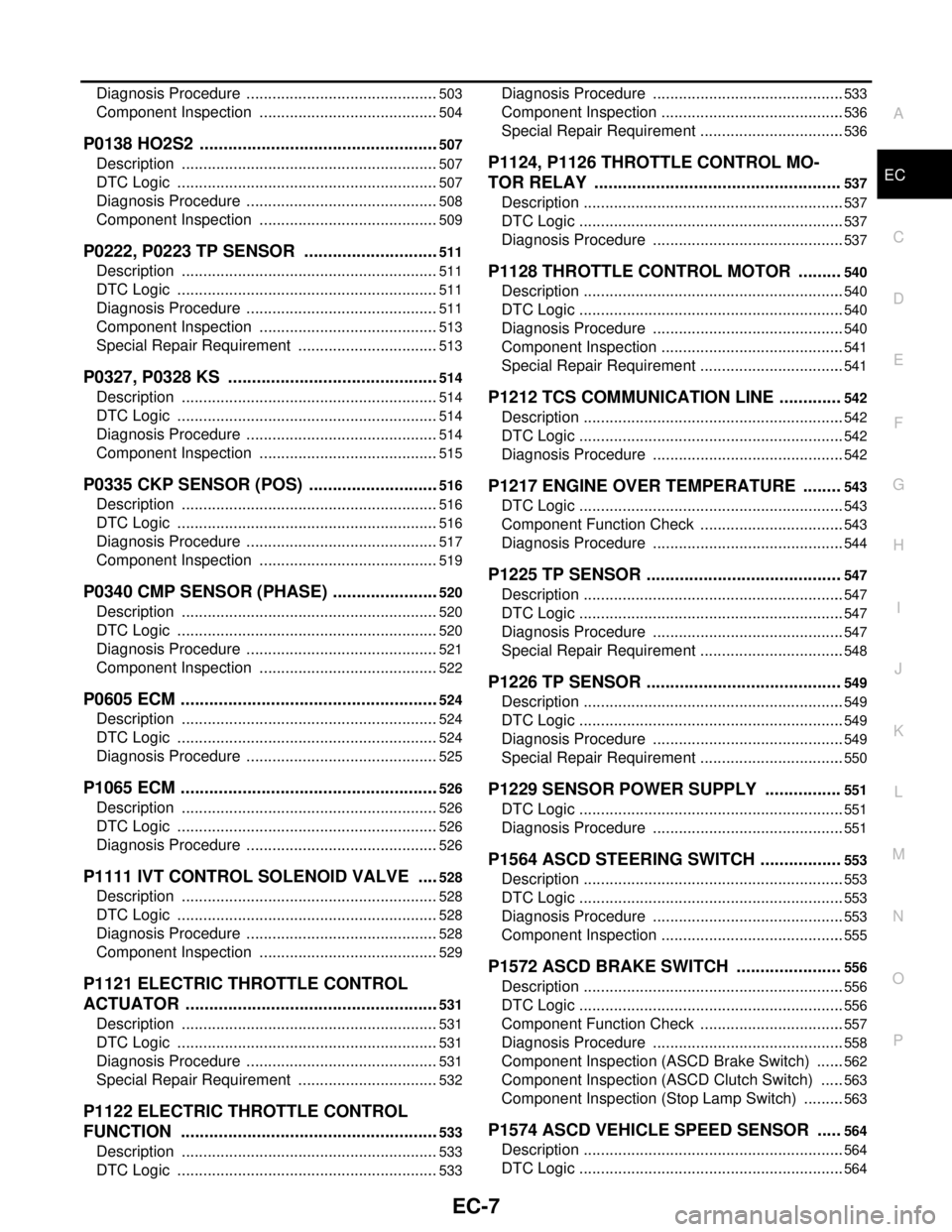
EC-7
C
D
E
F
G
H
I
J
K
L
M
ECA
N
O
P Diagnosis Procedure .............................................
503
Component Inspection ..........................................504
P0138 HO2S2 ...................................................507
Description ............................................................507
DTC Logic .............................................................507
Diagnosis Procedure .............................................508
Component Inspection ..........................................509
P0222, P0223 TP SENSOR .............................511
Description ............................................................511
DTC Logic .............................................................511
Diagnosis Procedure .............................................511
Component Inspection ..........................................513
Special Repair Requirement .................................513
P0327, P0328 KS .............................................514
Description ............................................................514
DTC Logic .............................................................514
Diagnosis Procedure .............................................514
Component Inspection ..........................................515
P0335 CKP SENSOR (POS) ............................516
Description ............................................................516
DTC Logic .............................................................516
Diagnosis Procedure .............................................517
Component Inspection ..........................................519
P0340 CMP SENSOR (PHASE) .......................520
Description ............................................................520
DTC Logic .............................................................520
Diagnosis Procedure .............................................521
Component Inspection ..........................................522
P0605 ECM .......................................................524
Description ............................................................524
DTC Logic .............................................................524
Diagnosis Procedure .............................................525
P1065 ECM .......................................................526
Description ............................................................526
DTC Logic .............................................................526
Diagnosis Procedure .............................................526
P1111 IVT CONTROL SOLENOID VALVE .....528
Description ............................................................528
DTC Logic .............................................................528
Diagnosis Procedure .............................................528
Component Inspection ..........................................529
P1121 ELECTRIC THROTTLE CONTROL
ACTUATOR ......................................................
531
Description ............................................................531
DTC Logic .............................................................531
Diagnosis Procedure .............................................531
Special Repair Requirement .................................532
P1122 ELECTRIC THROTTLE CONTROL
FUNCTION .......................................................
533
Description ............................................................533
DTC Logic .............................................................533
Diagnosis Procedure .............................................533
Component Inspection ...........................................536
Special Repair Requirement ..................................536
P1124, P1126 THROTTLE CONTROL MO-
TOR RELAY ....................................................
537
Description .............................................................537
DTC Logic ..............................................................537
Diagnosis Procedure .............................................537
P1128 THROTTLE CONTROL MOTOR .........540
Description .............................................................540
DTC Logic ..............................................................540
Diagnosis Procedure .............................................540
Component Inspection ...........................................541
Special Repair Requirement ..................................541
P1212 TCS COMMUNICATION LINE .............542
Description .............................................................542
DTC Logic ..............................................................542
Diagnosis Procedure .............................................542
P1217 ENGINE OVER TEMPERATURE ........543
DTC Logic ..............................................................543
Component Function Check ..................................543
Diagnosis Procedure .............................................544
P1225 TP SENSOR .........................................547
Description .............................................................547
DTC Logic ..............................................................547
Diagnosis Procedure .............................................547
Special Repair Requirement ..................................548
P1226 TP SENSOR .........................................549
Description .............................................................549
DTC Logic ..............................................................549
Diagnosis Procedure .............................................549
Special Repair Requirement ..................................550
P1229 SENSOR POWER SUPPLY ................551
DTC Logic ..............................................................551
Diagnosis Procedure .............................................551
P1564 ASCD STEERING SWITCH .................553
Description .............................................................553
DTC Logic ..............................................................553
Diagnosis Procedure .............................................553
Component Inspection ...........................................555
P1572 ASCD BRAKE SWITCH ......................556
Description .............................................................556
DTC Logic ..............................................................556
Component Function Check ..................................557
Diagnosis Procedure .............................................558
Component Inspection (ASCD Brake Switch) .......562
Component Inspection (ASCD Clutch Switch) ......563
Component Inspection (Stop Lamp Switch) ..........563
P1574 ASCD VEHICLE SPEED SENSOR .....564
Description .............................................................564
DTC Logic ..............................................................564