2007 NISSAN TIIDA torque
[x] Cancel search: torquePage 218 of 5883

BR-26
< ON-VEHICLE REPAIR >
FRONT DISC BRAKE
4. Remove union bolt, and then remove brake hose from caliper
assembly.
5. Remove torque member mounting bolts from torque member,
and remove caliper assembly from vehicle.
INSTALLATION
1. Install caliper assembly to vehicle, and tighten mounting bolts to the specified torque. Refer to BR-24,
"Component" .
CAUTION:
Before installing torque member to vehicle, wipe oil and grease on mounting surface of steering
knuckle and torque member.
2. Install brake hose to caliper assembly. Refer to BR-14, "
Hydraulic Circuit" .
3. Refill with new brake fluid and bleed air. Refer to BR-8, "
Bleeding Brake System" .
4. Check front disc brake for drag.
5. Install tires to the vehicle.
Brake BurnishingINFOID:0000000001717009
Burnish the new braking surfaces according to following procedure after refinishing or replacing disc rotors,
pads, or if a soft pedal occurs at very low mileage.
CAUTION:
Be careful of vehicle speed because brake does not operate easily until pad and disc rotor are
securely fitted.
Only perform this procedure under safe road and traffic conditions. Use extreme caution.
1. Drive vehicle on straight, flat road.
2. Depress brake pedal with the power to stop vehicle within 3 to 5 seconds until the vehicle stops.
3. Drive without depressing brake pedal for a few minutes to cool brake.
4. Repeat steps 1 to 3 until pad and disc rotor are securely fitted.
WFIA0524E
Page 219 of 5883

REAR DISC BRAKE
BR-27
< ON-VEHICLE REPAIR >
C
D
E
G
H
I
J
K
L
MA
B
BR
N
O
P
REAR DISC BRAKE
ComponentINFOID:0000000001724666
WARNING:
Clean dust on caliper and brake pad with a vacuum dust collector. Do not blow with compressed air.
CAUTION:
While removing cylinder body, never depress the brake pedal because the piston will pop out.
It is not necessary to remove bolts on torque member and brake hose except for disassembly or
replacement of the cylinder body. In this case, hang cylinder body with a wire so that brake hose is
not under tension.
Do not damage piston boot.
Always replace shims and shim covers as a set when replacing brake pads.
Keep the rotor clean of brake fluid.
Burnish the brake contact surfaces when refinishing or replacing brake rotors, after replacing pads
or linings, or if a soft pedal occurs at very low mileage. Refer to BR-29, "
Brake Burnishing".
1. Connecting bolt 2. Brake hose 3. Copper washer
4. Cap 5. Air bleeder 6. Sliding pin
7. Cylinder body 8. Piston seal 9. Piston
10. Piston boot 11. Retaining ring 12. Inner shim cover
13. Inner shim 14. Inner pad 15. Pad retainer
16. Outer pad 17. Outer shim 18. Outer shim cover
19. Sliding pin boot 20. Torque member bolts 21. Torque member
: Front : Brake fluid 1: M-77 grease
2: M7439 grease 3: Rubber grease
AWFIA0085GB
Page 220 of 5883

BR-28
< ON-VEHICLE REPAIR >
REAR DISC BRAKE
Removal and Installation of Brake Pad
INFOID:0000000001724667
REMOVAL
1. Remove master cylinder reservoir cap.
2. Remove tires from vehicle with power tool.
3. Remove bottom sliding pin bolt.
4. Hang cylinder body with a wire, and remove pads, pad retainers,
shims from torque member.
INSTALLATION
1. Apply M-77 grease or equivalent between pad plate and shim, shim and shim cover, and shim cover and
piston. Refer to MA-19, "
Fluids and Lubricants".
2. Attach the inner shim and shim cover to the inner pad, and the outer shim and outer shim cover to the
outer pad.
3. Apply M7439 grease or equivalent to pad contact surface of pad retainers.
4. Attach the pad retainers and pads to the torque member.
5. Push the piston in so that the pad is firmly attached and attach the cylinder body to the torque member.
NOTE:
Using a disc brake piston tool (commercial service tool), makes it easier to push in the piston.
CAUTION:
By pushing in the piston, the brake fluid returns to the master cylinder reservoir tank. Watch the
level of the surface of the reservoir tank.
6. Install the sliding pin bolt and tighten to the specification. Refer to BR-27, "
Component".
7. Inspect brake fluid level, then install master cylinder reservoir cap.
8. Check brake for drag.
9. Attach the tires to the vehicle. Refer to WT-6, "
Rotation".
CAUTION:
Burnish the brake contact surfaces when refinishing or replacing brake rotors, after replacing
pads or linings, or if a soft pedal occurs at very low mileage. Refer to BR-29, "
Brake Burnishing".
Removal and Installation of Brake Caliper AssemblyINFOID:0000000001724668
REMOVAL
1. Remove master cylinder reservoir cap.
2. Remove tires from vehicle using power tool.
SBR042C
Page 221 of 5883
REAR DISC BRAKE
BR-29
< ON-VEHICLE REPAIR >
C
D
E
G
H
I
J
K
L
MA
B
BR
N
O
P
3. Drain brake fluid. Refer to BR-8, "Bleeding Brake System".
4. Remove connecting bolt and torque member bolts using power tool, and remove cylinder body.
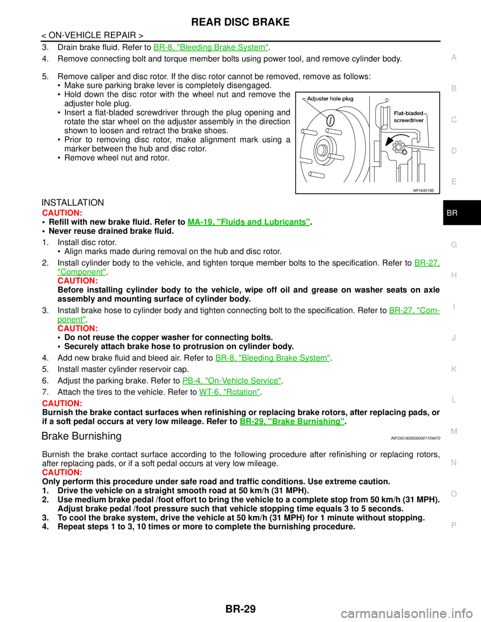
5. Remove caliper and disc rotor. If the disc rotor cannot be removed, remove as follows:
Make sure parking brake lever is completely disengaged.
Hold down the disc rotor with the wheel nut and remove the
adjuster hole plug.
Insert a flat-bladed screwdriver through the plug opening and
rotate the star wheel on the adjuster assembly in the direction
shown to loosen and retract the brake shoes.
Prior to removing disc rotor, make alignment mark using a
marker between the hub and disc rotor.
Remove wheel nut and rotor.
INSTALLATION
CAUTION:
Refill with new brake fluid. Refer to MA-19, "
Fluids and Lubricants".
Never reuse drained brake fluid.
1. Install disc rotor.
Align marks made during removal on the hub and disc rotor.
2. Install cylinder body to the vehicle, and tighten torque member bolts to the specification. Refer to BR-27,
"Component".
CAUTION:
Before installing cylinder body to the vehicle, wipe off oil and grease on washer seats on axle
assembly and mounting surface of cylinder body.
3. Install brake hose to cylinder body and tighten connecting bolt to the specification. Refer to BR-27, "
Com-
ponent".
CAUTION:
Do not reuse the copper washer for connecting bolts.
Securely attach brake hose to protrusion on cylinder body.
4. Add new brake fluid and bleed air. Refer to BR-8, "
Bleeding Brake System".
5. Install master cylinder reservoir cap.
6. Adjust the parking brake. Refer to PB-4, "
On-Vehicle Service".
7. Attach the tires to the vehicle. Refer to WT-6, "
Rotation".
CAUTION:
Burnish the brake contact surfaces when refinishing or replacing brake rotors, after replacing pads, or
if a soft pedal occurs at very low mileage. Refer to BR-29, "
Brake Burnishing".
Brake BurnishingINFOID:0000000001724670
Burnish the brake contact surface according to the following procedure after refinishing or replacing rotors,
after replacing pads, or if a soft pedal occurs at very low mileage.
CAUTION:
Only perform this procedure under safe road and traffic conditions. Use extreme caution.
1. Drive the vehicle on a straight smooth road at 50 km/h (31 MPH).
2. Use medium brake pedal /foot effort to bring the vehicle to a complete stop from 50 km/h (31 MPH).
Adjust brake pedal /foot pressure such that vehicle stopping time equals 3 to 5 seconds.
3. To cool the brake system, drive the vehicle at 50 km/h (31 MPH) for 1 minute without stopping.
4. Repeat steps 1 to 3, 10 times or more to complete the burnishing procedure.
WFIA0018E
Page 226 of 5883

BR-34
< DISASSEMBLY AND ASSEMBLY >
FRONT DISC BRAKE
FRONT DISC BRAKE
Disassembly and Assembly of Brake Caliper AssemblyINFOID:0000000001717023
NOTE:
Do not remove torque member, brake pads, shims and pad retainers, when disassembling or assembling cyl-
inder body.
DISASSEMBLY
1. Remove caliper assembly from vehicle. Refer to BR-25,
"Removal and Installation of Brake Caliper Assembly" .
2. Remove sliding pin bolts from cylinder body, and remove pads,
shims and pad retainers from torque member, if necessary.
CAUTION:
When removing pad retainer from torque member, lift the
pad retainer in the direction shown by arrow, so as not to
deform it.
3. Remove sliding pins and sliding pin boots from torque member.
4. Place a wooden block as shown, and blow air from union bolt
mounting hole to remove piston and piston boot.
CAUTION:
Do not get fingers caught in the piston.
5. Remove piston seal with a flat-bladed screwdriver.
CAUTION:
Be careful not to damage the inner wall of cylinder.
INSPECTION AFTER DISASSEMBLY
Cylinder Body
Check the inner wall of cylinder for corrosion, wear, and damage. Replace cylinder body as necessary.
CAUTION:
Clean cylinder body using new brake fluid. Never use mineral oils such as gasoline or kerosene.
Torque Member
Check for wear, cracks, and damage. Replace torque member as necessary..
Piston
Check piston surface for corrosion, wear, and damage. Replace piston as necessary.
CAUTION:
The piston sliding surface is plated. Do not polish with sandpaper.
Sliding Pin, Sliding Pin Bolt, and Sliding Pin Boot
SBR556E
WFIA0525E
SFIA2277E
Page 227 of 5883

FRONT DISC BRAKE
BR-35
< DISASSEMBLY AND ASSEMBLY >
C
D
E
G
H
I
J
K
L
MA
B
BR
N
O
P
Check sliding pins, sliding pin bolts and sliding pin boots for wear, damage, and cracks. Replace applicable
part as necessary.
ASSEMBLY
CAUTION:
When assembling, use only specified rubber lubricant.
1. Apply polyglycol ether based lubricant to new piston seal and
install them to cylinder body.
2. Apply rubber grease to piston boot and apply brake fluid to pis-
ton. Cover the piston end with piston boot, and install cylinder-
side lip on piston boot properly into groove on cylinder body.
3. Press piston into cylinder body by hand to assemble piston-side
lip on piston boot properly into a groove on piston.
CAUTION:
Press piston evenly and change pressing point to prevent
inner wall of cylinder from being rubbed.
4. Install sliding pins and sliding pin boots to the torque member.
5. If pads, shims and pad retainers were removed, install them to torque member. Refer to BR-24, "
Removal
and Installation of Brake Pad" .
6. Install cylinder body to torque member.
7. Install sliding pin bolts.
8. Install caliper assembly to vehicle. Refer to BR-25, "
Removal and Installation of Brake Caliper Assembly"
.
9. Tighten sliding pin bolts to specified torque. Refer to BR-24, "
Component" .
DISC ROTOR INSPECTION
Visual Inspection
Check surfaces of disc rotor for uneven wear, cracks, and serious damage. Replace applicable part as neces-
sary.
Runout Inspection
1. Using wheel nuts, secure disc rotor to wheels hub 2 or more positions.
SFIA2278E
SFIA3074E
SFIA2279E
Page 229 of 5883
REAR DISC BRAKE
BR-37
< DISASSEMBLY AND ASSEMBLY >
C
D
E
G
H
I
J
K
L
MA
B
BR
N
O
P
REAR DISC BRAKE
Disassembly and AssemblyINFOID:0000000001724669
DISASSEMBLY
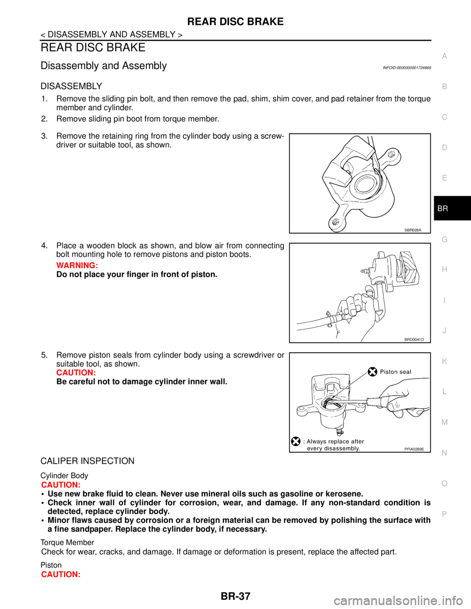
1. Remove the sliding pin bolt, and then remove the pad, shim, shim cover, and pad retainer from the torque
member and cylinder.
2. Remove sliding pin boot from torque member.
3. Remove the retaining ring from the cylinder body using a screw-
driver or suitable tool, as shown.
4. Place a wooden block as shown, and blow air from connecting
bolt mounting hole to remove pistons and piston boots.
WARNING:
Do not place your finger in front of piston.
5. Remove piston seals from cylinder body using a screwdriver or
suitable tool, as shown.
CAUTION:
Be careful not to damage cylinder inner wall.
CALIPER INSPECTION
Cylinder Body
CAUTION:
Use new brake fluid to clean. Never use mineral oils such as gasoline or kerosene.
Check inner wall of cylinder for corrosion, wear, and damage. If any non-standard condition is
detected, replace cylinder body.
Minor flaws caused by corrosion or a foreign material can be removed by polishing the surface with
a fine sandpaper. Replace the cylinder body, if necessary.
Torque Member
Check for wear, cracks, and damage. If damage or deformation is present, replace the affected part.
Piston
CAUTION:
SBR028A
BRD0041D
PFIA0269E
Page 231 of 5883
REAR DISC BRAKE
BR-39
< DISASSEMBLY AND ASSEMBLY >
C
D
E
G
H
I
J
K
L
MA
B
BR
N
O
P
5. Attach the sliding pin bolt and sliding pin boot to the torque member.
6. Apply PBC (Poly Butyl Cuprysil) grease or silicone-based grease to the rear of the pad and to both sides
of the shim, and attach the inner shim and shim cover to the inner pad, and the outer shim and outer shim
cover to the outer pad.
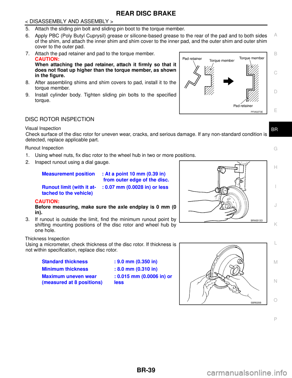
7. Attach the pad retainer and pad to the torque member.
CAUTION:
When attaching the pad retainer, attach it firmly so that it
does not float up higher than the torque member, as shown
in the figure.
8. After assembling shims and shim covers to pad, install it to the
torque member.
9. Install cylinder body. Tighten sliding pin bolts to the specified
torque.
DISC ROTOR INSPECTION
Visual Inspection
Check surface of the disc rotor for uneven wear, cracks, and serious damage. If any non-standard condition is
detected, replace applicable part.
Runout Inspection
1. Using wheel nuts, fix disc rotor to the wheel hub in two or more positions.
2. Inspect runout using a dial gauge.
CAUTION:
Before measuring, make sure the axle endplay is 0 mm (0
in).
3. If runout is outside the limit, find the minimum runout point by
shifting mounting positions of the disc rotor and wheel hub by
one hole.
Thickness Inspection
Using a micrometer, check thickness of the disc rotor. If thickness is
not within specification, replace disc rotor.
PFIA0273E
Measurement position : At a point 10 mm (0.39 in)
from outer edge of the disc.
Runout limit (with it at-
tached to the vehicle): 0.07 mm (0.0028 in) or less
BRA0013D
Standard thickness : 9.0 mm (0.350 in)
Minimum thickness : 8.0 mm (0.310 in)
Maximum uneven wear
(measured at 8 positions): 0.015 mm (0.0006 in) or
less
SBR020B