2007 NISSAN TIIDA brake rotor
[x] Cancel search: brake rotorPage 228 of 5883
BR-36
< DISASSEMBLY AND ASSEMBLY >
FRONT DISC BRAKE
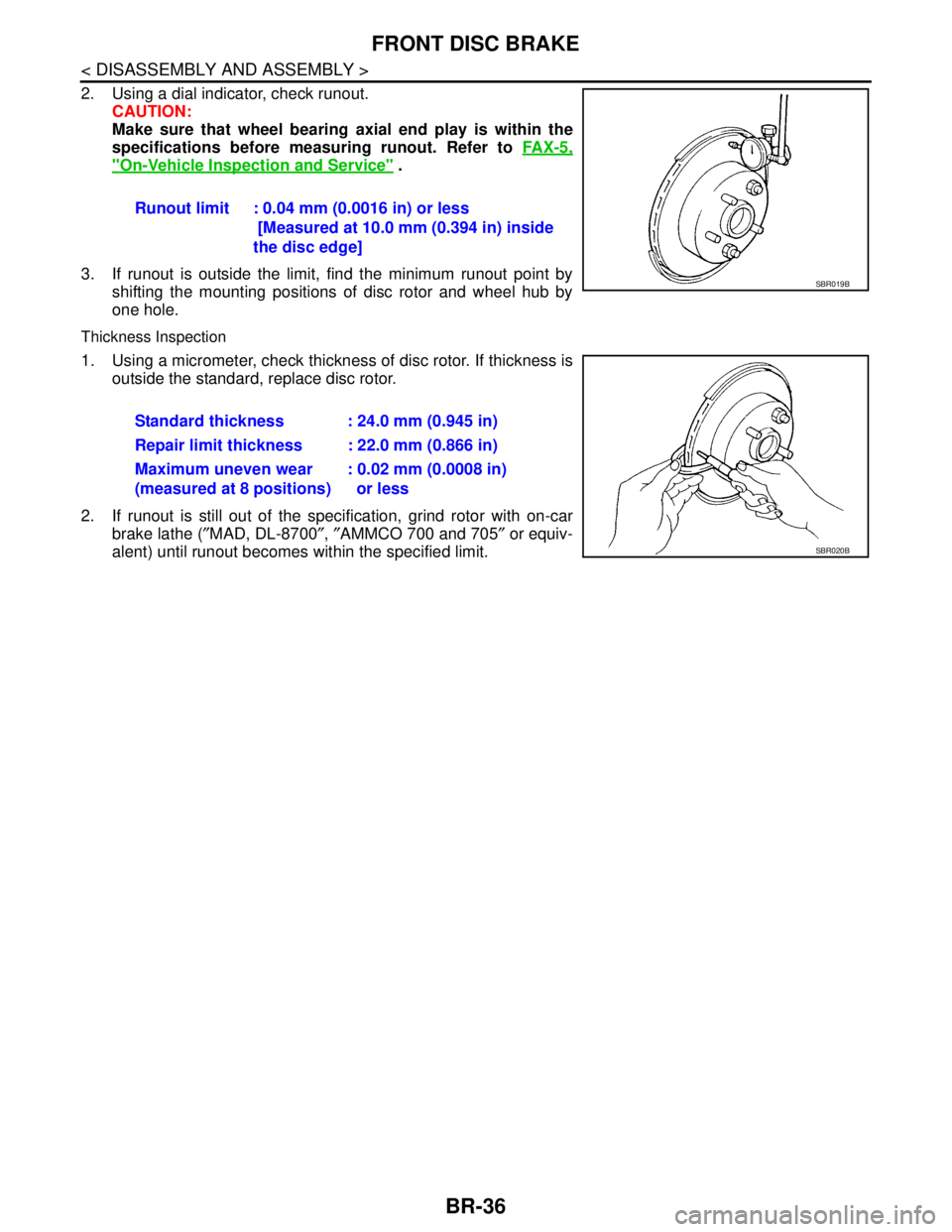
2. Using a dial indicator, check runout.
CAUTION:
Make sure that wheel bearing axial end play is within the
specifications before measuring runout. Refer to FA X - 5 ,
"On-Vehicle Inspection and Service" .
3. If runout is outside the limit, find the minimum runout point by
shifting the mounting positions of disc rotor and wheel hub by
one hole.
Thickness Inspection
1. Using a micrometer, check thickness of disc rotor. If thickness is
outside the standard, replace disc rotor.
2. If runout is still out of the specification, grind rotor with on-car
brake lathe (″MAD, DL-8700″, ″AMMCO 700 and 705″ or equiv-
alent) until runout becomes within the specified limit.Runout limit : 0.04 mm (0.0016 in) or less
[Measured at 10.0 mm (0.394 in) inside
the disc edge]
SBR019B
Standard thickness : 24.0 mm (0.945 in)
Repair limit thickness : 22.0 mm (0.866 in)
Maximum uneven wear
(measured at 8 positions): 0.02 mm (0.0008 in)
or less
SBR020B
Page 231 of 5883
REAR DISC BRAKE
BR-39
< DISASSEMBLY AND ASSEMBLY >
C
D
E
G
H
I
J
K
L
MA
B
BR
N
O
P
5. Attach the sliding pin bolt and sliding pin boot to the torque member.
6. Apply PBC (Poly Butyl Cuprysil) grease or silicone-based grease to the rear of the pad and to both sides
of the shim, and attach the inner shim and shim cover to the inner pad, and the outer shim and outer shim
cover to the outer pad.
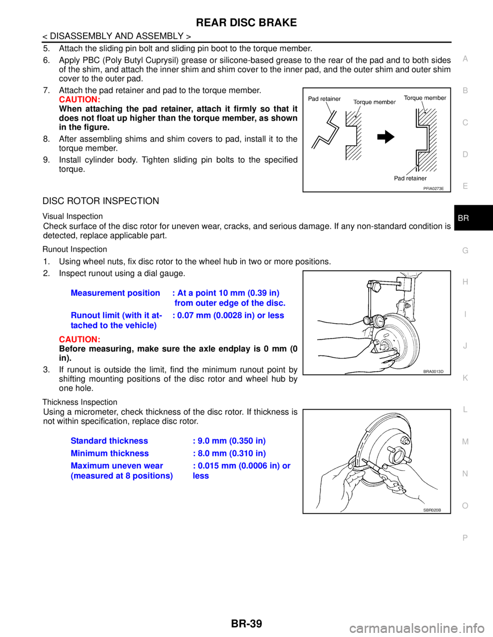
7. Attach the pad retainer and pad to the torque member.
CAUTION:
When attaching the pad retainer, attach it firmly so that it
does not float up higher than the torque member, as shown
in the figure.
8. After assembling shims and shim covers to pad, install it to the
torque member.
9. Install cylinder body. Tighten sliding pin bolts to the specified
torque.
DISC ROTOR INSPECTION
Visual Inspection
Check surface of the disc rotor for uneven wear, cracks, and serious damage. If any non-standard condition is
detected, replace applicable part.
Runout Inspection
1. Using wheel nuts, fix disc rotor to the wheel hub in two or more positions.
2. Inspect runout using a dial gauge.
CAUTION:
Before measuring, make sure the axle endplay is 0 mm (0
in).
3. If runout is outside the limit, find the minimum runout point by
shifting mounting positions of the disc rotor and wheel hub by
one hole.
Thickness Inspection
Using a micrometer, check thickness of the disc rotor. If thickness is
not within specification, replace disc rotor.
PFIA0273E
Measurement position : At a point 10 mm (0.39 in)
from outer edge of the disc.
Runout limit (with it at-
tached to the vehicle): 0.07 mm (0.0028 in) or less
BRA0013D
Standard thickness : 9.0 mm (0.350 in)
Minimum thickness : 8.0 mm (0.310 in)
Maximum uneven wear
(measured at 8 positions): 0.015 mm (0.0006 in) or
less
SBR020B
Page 232 of 5883

BR-40
< SERVICE DATA AND SPECIFICATIONS (SDS)
SERVICE DATA AND SPECIFICATIONS (SDS)
SERVICE DATA AND SPECIFICATIONS (SDS)
SERVICE DATA AND SPECIFICATIONS (SDS)
General SpecificationINFOID:0000000001716911
Brake PedalINFOID:0000000001716912
Unit: mm (in)
Check ValveINFOID:0000000001716913
Brake BoosterINFOID:0000000001716914
Vacuum type
Front Disc BrakeINFOID:0000000001716915
Unit: mm (in)
Front brake Brake model CLZ25VA
Cylinder bore diameter 57.2 mm (2.252 in)
Pad
Length × width × thickness125.6 mm × 46.0 mm × 9.5 mm
(4.945 in × 1.811 in × 0.374 in)
Rotor outer diameter × thickness 280 mm × 24.0 mm (11.02 in × 0.945 in)
Rear brake Brake model —
Cylinder bore diameter 34.93 mm (1.375 in)
Pad thickness 8.5 mm (0.335 in)
Rotor outer diameter × thickness292 mm × 9.0 mm
(11.50 in × 0.354 in)
Master cylinder Cylinder bore diameter 22.22 mm (0.875 in)
Control valve Valve model Electric brake force distribution
Brake booster Booster model C255
Diaphragm diameter 255 mm (10.04 in)
Recommended brake fluid Refer to MA-19
.
Brake pedal free height (from dash panel top surface)A/T model 172.4 - 182.4 (6.79 - 7.18)
M/T models 162.3 - 172.3 (6.39 - 6.78)
Brake pedal depressed height
[under a force of 490 N (50 kg-f, 110 lb-f) with the engine running]A/T model 98 (3.86) or more
M/T models 90 (3.54) or more
Clearance between brake pedal lever and the threaded end of stop lamp switch 0.74 - 1.96 (0.0291 - 0.0772)
Pedal play3 - 11 (0.12 - 0.43)
Vacuum leakage
[at vacuum of – 66.7 kPa (– 500 mmHg, – 19.69 inHg]Within 1.3 kPa (10 mmHg, 0.39 inHg) of vacuum for 15 seconds
Vacuum leakage
[at vacuum of – 66.7 kPa (– 500 mmHg, –19.69 inHg)]Within 3.3 kPa (25 mmHg, 0.98 inHg) of vacuum for 15 seconds
Input rod installation standard dimension 154 - 161 mm (6.06 - 6.34 in)
Brake modelCLZ25VA
Brake padStandard thickness (new) 9.5 (0.374)
Repair limit thickness 2.0 (0.079)
Page 233 of 5883

SERVICE DATA AND SPECIFICATIONS (SDS)
BR-41
< SERVICE DATA AND SPECIFICATIONS (SDS)
C
D
E
G
H
I
J
K
L
MA
B
BR
N
O
P
Rear Disc BrakeINFOID:0000000001716916
Unit: mm (in)
Disc rotorStandard thickness (new) 24.0 (0.945)
Repair limit thickness 22.0 (0.866)
Runout limit 0.04 (0.0016)
Maximum uneven wear (mea-
sured at 8 positions)0.02 mm (0.0008 in) or less
Brake model—
Brake padStandard thickness (new) 8.5 (0.335)
Repair limit thickness 2.0 (0.079)
DrumStandard thickness (new) 9.0 (0.354)
Repair limit inner diameter 8.0 (0.315)
Runout limit 0.07 (0.0028)
Maximum uneven wear (mea-
sured at 8 points)0.015 (0.00006)
Page 238 of 5883

BRC-5
C
D
E
G
H
I
J
K
L
MA
B
BRC
N
O
P Fail-Safe ................................................................
168
DTC No. Index ......................................................169
SYMPTOM DIAGNOSIS ............................171
VDC/TCS/ABS ..................................................171
Symptom Table .....................................................171
EXCESSIVE ABS FUNCTION OPERATION
FREQUENCY ...................................................
172
Diagnosis Procedure .............................................172
UNEXPECTED PEDAL REACTION ................173
Diagnosis Procedure .............................................173
THE BRAKING DISTANCE IS LONG ..............174
Diagnosis Procedure .............................................174
ABS FUNCTION DOES NOT OPERATE .........175
Diagnosis Procedure .............................................175
PEDAL VIBRATION OR ABS OPERATION
SOUND OCCURS ............................................
176
Diagnosis Procedure .............................................176
VEHICLE JERKS DURING VDC/TCS/ABS
CONTROL ........................................................
177
Diagnosis Procedure .............................................177
NORMAL OPERATING CONDITION ...............178
Description ............................................................178
PRECAUTION ............................................179
PRECAUTIONS ...............................................179
Precaution for Supplemental Restraint System
(SRS) "AIR BAG" and "SEAT BELT PRE-TEN-
SIONER" ...............................................................
179
Precaution for Brake System .................................179
Precaution for Brake Control .................................179
Diagnosis Precaution .............................................180
Precaution for Harness Repair ..............................180
PREPARATION .........................................181
PREPARATION ...............................................181
Special Service Tool ..............................................181
REMOVAL AND INSTALLATION .............182
WHEEL SENSORS .........................................182
Removal and Installation .......................................182
SENSOR ROTOR ............................................183
Removal and Installation .......................................183
ACTUATOR AND ELECTRIC UNIT (ASSEM-
BLY) ................................................................
184
Removal and Installation .......................................184
YAW RATE/SIDE G SENSOR ........................185
Removal and Installation .......................................185
STEERING ANGLE SENSOR .........................186
Removal and Installation .......................................186
Page 306 of 5883
![NISSAN TIIDA 2007 Service Repair Manual ABS
BRC-73
< SYMPTOM DIAGNOSIS >[ABS]
C
D
E
G
H
I
J
K
L
MA
B
BRC
N
O
P
SYMPTOM DIAGNOSIS
ABS
Symptom TableINFOID:0000000001731343
If ABS warning lamp, VDC OFF indicator lamp and SLIP indicator lamp tu](/manual-img/5/57395/w960_57395-305.png "NISSAN TIIDA 2007 Service Repair Manual ABS
BRC-73
< SYMPTOM DIAGNOSIS >[ABS]
C
D
E
G
H
I
J
K
L
MA
B
BRC
N
O
P
SYMPTOM DIAGNOSIS
ABS
Symptom TableINFOID:0000000001731343
If ABS warning lamp, VDC OFF indicator lamp and SLIP indicator lamp tu")
ABS
BRC-73
< SYMPTOM DIAGNOSIS >[ABS]
C
D
E
G
H
I
J
K
L
MA
B
BRC
N
O
P
SYMPTOM DIAGNOSIS
ABS
Symptom TableINFOID:0000000001731343
If ABS warning lamp, VDC OFF indicator lamp and SLIP indicator lamp turn ON, perform self-diagnosis.
NOTE:
1: The ABS does not operate when the speed is 10 km/h (6 MPH) or less.
2: Under the following conditions, ABS is activated and vibration is felt when brake pedal is lightly depressed. However, this is normal.
- When shifting gears
- When driving on slippery road
- During cornering at high speed
- When passing over bumps or grooves [at approximately 50 mm (1.97 in) or more]
- When pulling away just after starting engine [at approximately 10 km/h (6 MPH) or higher]Symptom Check item Reference
Excessive ABS function operation fre-
quencyBrake force distribution
BRC-74, "
Diagno-
sis Procedure"Looseness of front and rear axle
Wheel sensor and rotor system
Unexpected pedal reactionBrake pedal stroke
BRC-75, "
Diagno-
sis Procedure"Make sure the braking force is sufficient when the ABS is not operating.
The braking distance is long Check stopping distance when the ABS is not operating.BRC-76, "
Diagno-
sis Procedure"
ABS function does not operate (Note 1) ABS actuator and electric unit (control unit)BRC-77, "Diagno-
sis Procedure"
Pedal vibration or ABS operation sound
occurs (Note 2)Brake pedal
BRC-78, "Diagno-
sis Procedure"ABS actuator and electric unit (control unit)
Page 307 of 5883
![NISSAN TIIDA 2007 Service Repair Manual BRC-74
< SYMPTOM DIAGNOSIS >[ABS]
EXCESSIVE ABS FUNCTION OPERATION FREQUENCY
EXCESSIVE ABS FUNCTION OPERATION FREQUENCY
Diagnosis ProcedureINFOID:0000000001731344
1.CHECK START
Check front and rear br](/manual-img/5/57395/w960_57395-306.png "NISSAN TIIDA 2007 Service Repair Manual BRC-74
< SYMPTOM DIAGNOSIS >[ABS]
EXCESSIVE ABS FUNCTION OPERATION FREQUENCY
EXCESSIVE ABS FUNCTION OPERATION FREQUENCY
Diagnosis ProcedureINFOID:0000000001731344
1.CHECK START
Check front and rear br")
BRC-74
< SYMPTOM DIAGNOSIS >[ABS]
EXCESSIVE ABS FUNCTION OPERATION FREQUENCY
EXCESSIVE ABS FUNCTION OPERATION FREQUENCY
Diagnosis ProcedureINFOID:0000000001731344
1.CHECK START
Check front and rear brake force distribution using a brake tester.
Is the inspection result normal?
YES >> GO TO 2
NO >> Check brake system.
2.CHECK FRONT AND REAR AXLE
Make sure that there is no excessive play in the front and rear axles. Refer to front: FA X - 6 , "
On-Vehicle
Inspection and Service", Rear: RAX-5, "On-Vehicle Inspection and Service".
Is the inspection result normal?
YES >> GO TO 3
NO >> Repair or replace malfunctioning components.
3.CHECK WHEEL SENSOR AND SENSOR ROTOR
Check the following.
Wheel sensor installation for damage.
Sensor rotor installation for damage.
Wheel sensor connector connection.
Wheel sensor harness inspection.
Is the inspection result normal?
YES >> GO TO 4
NO >> Replace wheel sensor or sensor rotor. Refer to BRC-83, "
Removal and Installation".
Repair harness.
4.CHECK ABS WARNING LAMP DISPLAY
Make sure that the ABS warning lamp is turned off after the ignition switch is turned ON or when driving.
Is the ABS warning lamp illuminated?
YES >> Perform self-diagnosis. Refer to BRC-25, "CONSULT-III Function (ABS)".
NO >> Normal
Page 317 of 5883
![NISSAN TIIDA 2007 Service Repair Manual BRC-84
< REMOVAL AND INSTALLATION >[ABS]
SENSOR ROTOR
SENSOR ROTOR
Removal and InstallationINFOID:0000000001691409
FRONT
Because the sensor rotor is integrated with the wheel bearing, replace it tog](/manual-img/5/57395/w960_57395-316.png "NISSAN TIIDA 2007 Service Repair Manual BRC-84
< REMOVAL AND INSTALLATION >[ABS]
SENSOR ROTOR
SENSOR ROTOR
Removal and InstallationINFOID:0000000001691409
FRONT
Because the sensor rotor is integrated with the wheel bearing, replace it tog")
BRC-84
< REMOVAL AND INSTALLATION >[ABS]
SENSOR ROTOR
SENSOR ROTOR
Removal and InstallationINFOID:0000000001691409
FRONT
Because the sensor rotor is integrated with the wheel bearing, replace it together with the wheel bearing
assembly. Refer to FAX-7, "
Removal and Installation".
REAR
During removal and installation, remove the wheel hub (brake drum). Refer to RAX-6, "Removal and Instal-
lation".
CAUTION:
The sensor rotor is a non-reusable part, it must be replaced by an new part when removing it.