Page 4884 of 5883
![NISSAN TIIDA 2007 Service Repair Manual STC-10
< COMPONENT DIAGNOSIS >[EPS]
C1601 BATTERY POWER SUPPLY
NG >> Check the following. If any items are damaged, repair or replace damaged parts.
60 A fusible link (letter m, located in the fuse](/manual-img/5/57395/w960_57395-4883.png "NISSAN TIIDA 2007 Service Repair Manual STC-10
< COMPONENT DIAGNOSIS >[EPS]
C1601 BATTERY POWER SUPPLY
NG >> Check the following. If any items are damaged, repair or replace damaged parts.
60 A fusible link (letter m, located in the fuse")
STC-10
< COMPONENT DIAGNOSIS >[EPS]
C1601 BATTERY POWER SUPPLY
NG >> Check the following. If any items are damaged, repair or replace damaged parts.
60 A fusible link (letter m, located in the fuse and fusible link box).
10 A fuse [No. 2, located in the fuse block (J/B)].
Harness for short or open between battery and EPS control unit harness connector M54 termi-
nal 17.
Harness for short or open between ignition switch and EPS control unit harness connector M53
terminal 10.
2.CHECK EPS CONTROL UNIT GROUND CIRCUIT
1. Turn ignition switch OFF.
2. Disconnect EPS control unit harness connector.
3. Check continuity between EPS control unit harness connector
M54 terminal 18 and ground.
Also check harness for short to power.
4. Connect EPS control unit harness connector.
OK or NG
OK >> GO TO 3.
NG >> Repair open circuit, short to ground or short to power in
harness or connectors.
3.CHECK DTC
1. Start engine.
Does EPS warning lamp turn OFF?
YES >>INSPECTION END
NO >> Perform self-diagnosis, repair or replace damaged parts. Refer to STC-7, "
CONSULT-III Function
(EPS)".
Special Repair Requirement (Models with ESP)INFOID:0000000001716734
1.ADJUSTMENT OF STEERING ANGLE SENSOR NEUTRAL POSITION
Always perform the neutral position adjustment for the steering angle sensor, when replacing the EPS control
unit. Refer to BRC-90, "
ADJUSTMENT OF STEERING ANGLE SENSOR NEUTRAL POSITION : Descrip-
tion".
>> END
Connector Terminal Continuity
M54 18 Yes
AWGIA0029ZZ
Page 4905 of 5883
![NISSAN TIIDA 2007 Service Repair Manual EPS WARNING LAMP DOES NOT TURN OFF
STC-31
< SYMPTOM DIAGNOSIS >[EPS]
C
D
E
F
H
I
J
K
L
MA
B
STC
N
O
P
EPS WARNING LAMP DOES NOT TURN OFF
Diagnosis ProcedureINFOID:0000000001697734
SYMPTOM:
EPS warnin](/manual-img/5/57395/w960_57395-4904.png "NISSAN TIIDA 2007 Service Repair Manual EPS WARNING LAMP DOES NOT TURN OFF
STC-31
< SYMPTOM DIAGNOSIS >[EPS]
C
D
E
F
H
I
J
K
L
MA
B
STC
N
O
P
EPS WARNING LAMP DOES NOT TURN OFF
Diagnosis ProcedureINFOID:0000000001697734
SYMPTOM:
EPS warnin")
EPS WARNING LAMP DOES NOT TURN OFF
STC-31
< SYMPTOM DIAGNOSIS >[EPS]
C
D
E
F
H
I
J
K
L
MA
B
STC
N
O
P
EPS WARNING LAMP DOES NOT TURN OFF
Diagnosis ProcedureINFOID:0000000001697734
SYMPTOM:
EPS warning lamp does not turn OFF for several seconds after starting the engine.
DIAGNOSTIC PROCEDURE
1.CHECK SELF-DIAGNOSTIC RESULTS
Perform self-diagnosis. Refer to STC-7, "
CONSULT-III Function (EPS)".
Is any malfunction detected by self-diagnosis?
YES >> Check the malfunctioning system.
NO >> GO TO 2.
2.CHECK EPS CONTROL UNIT POWER SUPPLY CIRCUIT
1. Turn ignition switch OFF.
2. Disconnect EPS control unit harness connector.
3. Turn ignition switch ON. (Do not start engine.)
4. Check voltage between EPS control unit harness connector
M53 (A) terminal 10 and M54 (B) terminal 17 and ground.
5. Turn ignition switch OFF.
6. Check voltage between EPS control unit harness connector
M53 (A) terminal 10 and M54 (B) terminal 17 and ground.
7. Connect EPS control unit harness connector.
OK or NG
OK >> GO TO 3.
NG >> Check the following. If any items are damaged, repair
or replace damaged parts.
60 A fusible link (letter m , located in the fuse and fusible link box).
10 A fuse [No. 2, located in the fuse block (J/B)].
Harness for short or open between battery and EPS control unit harness connector M54 termi-
nal 17.
Harness for short or open between ignition switch and EPS control unit harness connector M53
terminal 10.
3.CHECK EPS CONTROL UNIT GROUND CIRCUIT
1. Turn ignition switch OFF.
2. Disconnect EPS control unit harness connector.
Connector Terminal Voltage
(A) M53 10 – Ground Battery voltage
(B) M54 17 – Ground Battery voltage
AWGIA0031ZZ
Connector Terminal Voltage
(A) M53 10 – Ground Approx. 0 V
(B) M54 17 – Ground Battery voltage
AWGIA0028ZZ
Page 5741 of 5883
WCS-26
< COMPONENT DIAGNOSIS >
KEY SWITCH SIGNAL CIRCUIT (WITH INTELLIGENT KEY)
KEY SWITCH SIGNAL CIRCUIT (WITH INTELLIGENT KEY)
DescriptionINFOID:0000000001722936
Transmits a key switch signal to the BCM.
Component Function CheckINFOID:0000000001722937
1.CHECK BCM INPUT SIGNAL
Select “DATA MONITOR” for “BCM” and check the “KEY IN SW” monitor value.
>> Inspection End.
Diagnosis ProcedureINFOID:0000000001722938
1.CHECK FUSE
Check if the key switch and ignition knob switch 10A fuse (No. 31, located in the fuse and relay box) is blown.
Is the fuse blown?
YES >> Be sure to repair the cause of malfunction before installing new fuse.
NO >> GO TO 2
2.CHECK BCM INPUT SIGNAL
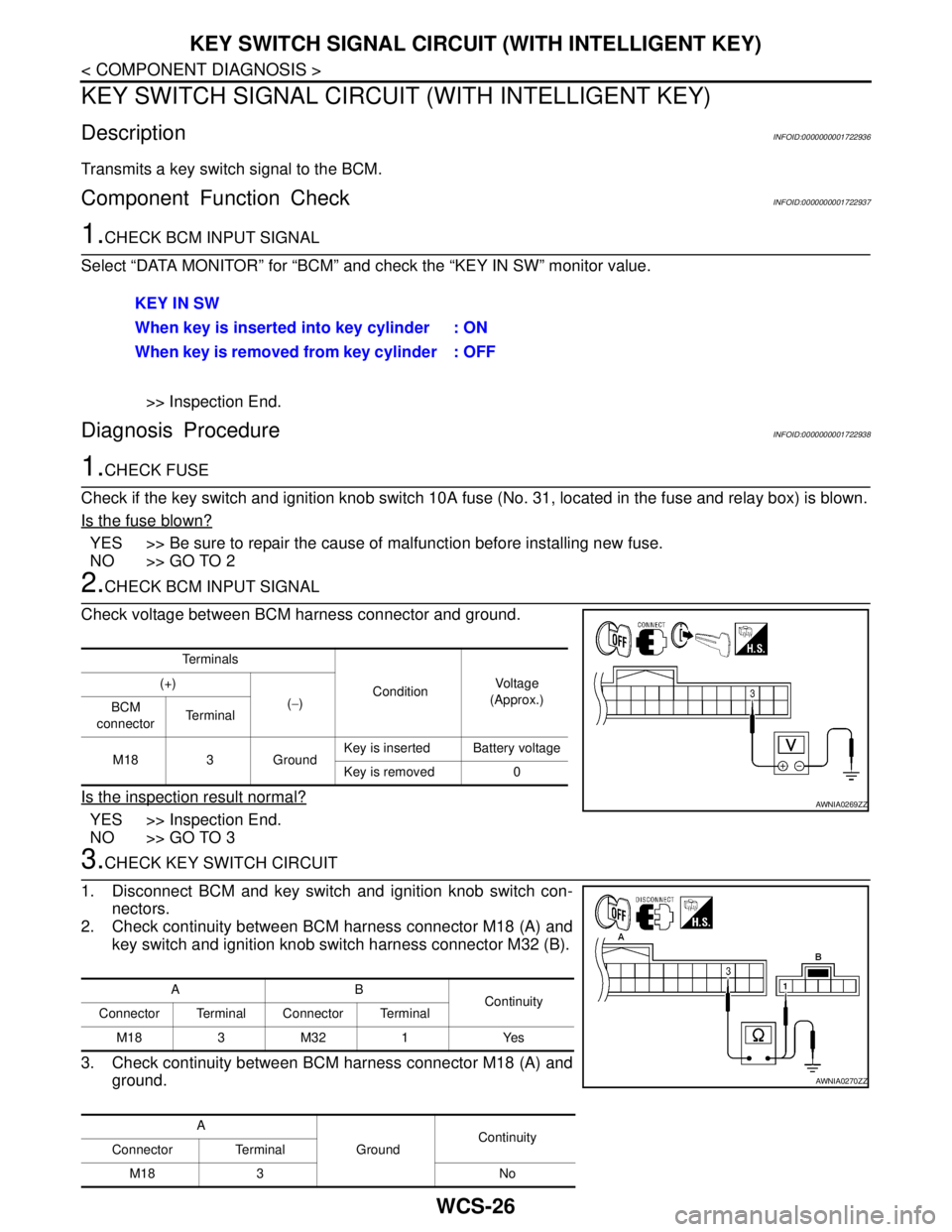
Check voltage between BCM harness connector and ground.
Is the inspection result normal?
YES >> Inspection End.
NO >> GO TO 3
3.CHECK KEY SWITCH CIRCUIT
1. Disconnect BCM and key switch and ignition knob switch con-
nectors.
2. Check continuity between BCM harness connector M18 (A) and
key switch and ignition knob switch harness connector M32 (B).
3. Check continuity between BCM harness connector M18 (A) and
ground.KEY IN SW
When key is inserted into key cylinder : ON
When key is removed from key cylinder : OFF
Te r m i n a l s
ConditionVo l ta g e
(Approx.) (+)
(−)
BCM
connectorTe r m i n a l
M18 3 GroundKey is inserted Battery voltage
Key is removed 0
AWNIA0269ZZ
AB
Continuity
Connector Terminal Connector Terminal
M183M321 Yes
A
GroundContinuity
Connector Terminal
M18 3 No
AWNIA0270ZZ
Page 5819 of 5883
WIPER AND WASHER FUSE, FUSIBLE LINK
WW-17
< COMPONENT DIAGNOSIS >
C
D
E
F
G
H
I
J
K
MA
B
WW
N
O
P
COMPONENT DIAGNOSIS
WIPER AND WASHER FUSE, FUSIBLE LINK
DescriptionINFOID:0000000001366608
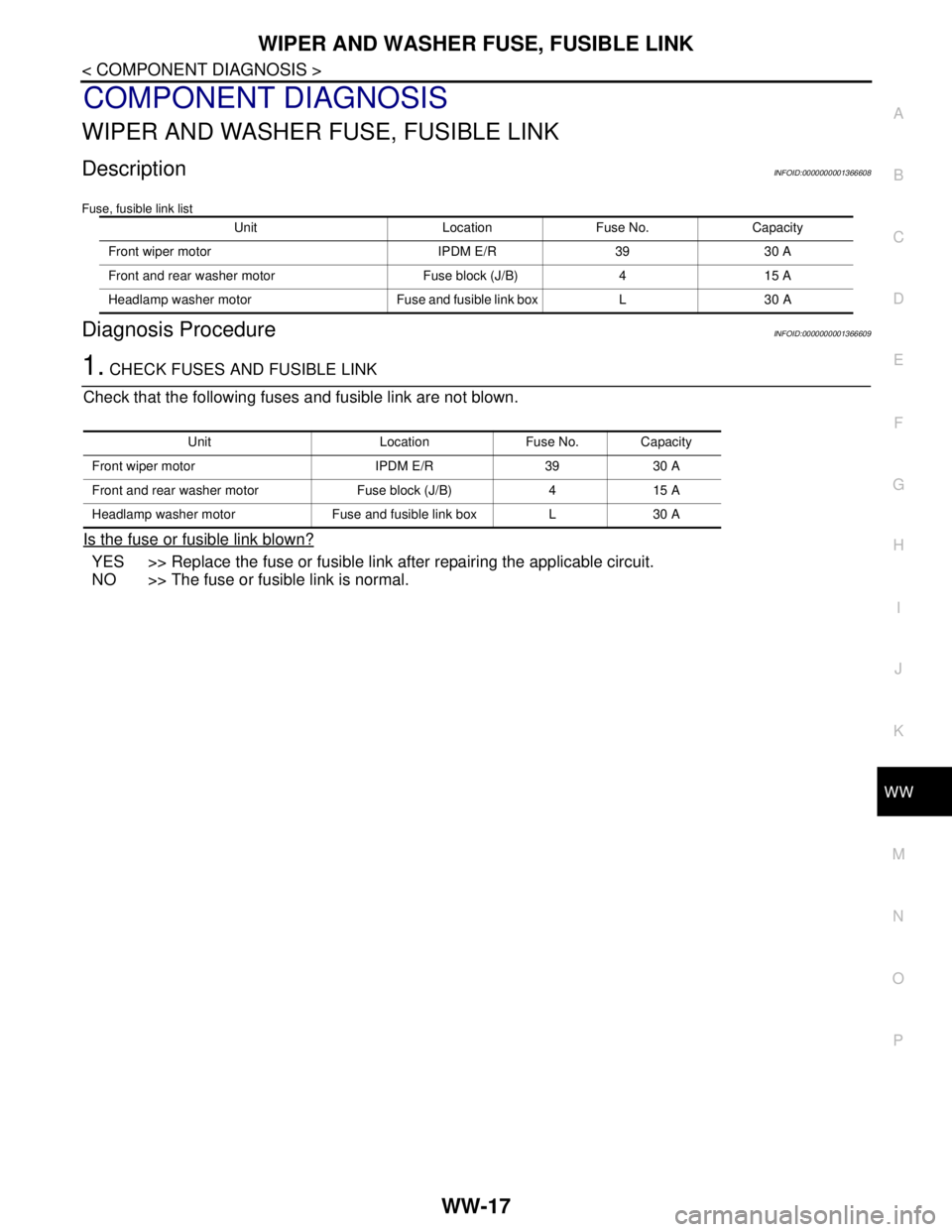
Fuse, fusible link list
Diagnosis ProcedureINFOID:0000000001366609
1. CHECK FUSES AND FUSIBLE LINK
Check that the following fuses and fusible link are not blown.
Is the fuse or fusible link blown?
YES >> Replace the fuse or fusible link after repairing the applicable circuit.
NO >> The fuse or fusible link is normal.
Unit Location Fuse No. Capacity
Front wiper motor IPDM E/R 39 30 A
Front and rear washer motor Fuse block (J/B) 4 15 A
Headlamp washer motor Fuse and fusible link box L 30 A
Unit Location Fuse No. Capacity
Front wiper motor IPDM E/R 39 30 A
Front and rear washer motor Fuse block (J/B) 4 15 A
Headlamp washer motor Fuse and fusible link box L 30 A
Page 5835 of 5883
HEADLAMP WASHER CIRCUIT
WW-33
< COMPONENT DIAGNOSIS >
C
D
E
F
G
H
I
J
K
MA
B
WW
N
O
P
HEADLAMP WASHER CIRCUIT
Component Function CheckINFOID:0000000001366626
1. CHECK HEADLAMP WASHER OPERATION
CONSULT-III ACTIVE TEST
1. Select "HEAD LAMP WASHER" of IPDM E/R active test item.
2. While operating the test item, check headlamp washer operation.
Is the headlamp washer operation normally?
YES >> Headlamp washer circuit is normal.
NO >> Refer to WW-33, "
Diagnosis Procedure".
Diagnosis ProcedureINFOID:0000000001366627
1. CHECK HEADLAMP WASHER FUSIBLE LINK
1. Turn the ignition switch OFF.
2. Check that the following fusible link is not blown.
Is the fusible link blown?
YES >> Replace the fusible link after repairing the applicable circuit.
NO >> GO TO 2
2. CHECK HEADLAMP WASHER RELAY POWER SUPPLY
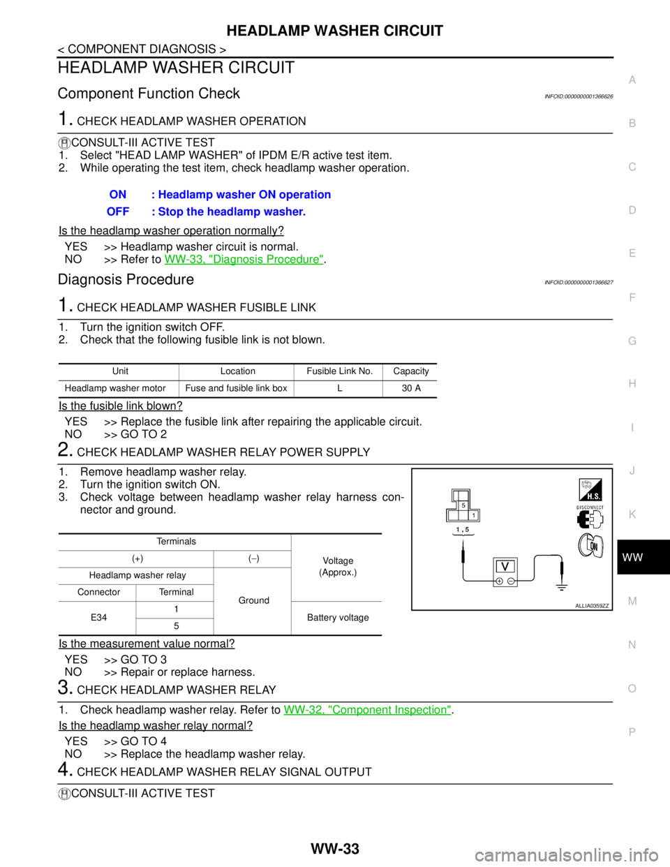
1. Remove headlamp washer relay.
2. Turn the ignition switch ON.
3. Check voltage between headlamp washer relay harness con-
nector and ground.
Is the measurement value normal?
YES >> GO TO 3
NO >> Repair or replace harness.
3. CHECK HEADLAMP WASHER RELAY
1. Check headlamp washer relay. Refer to WW-32, "
Component Inspection".
Is the headlamp washer relay normal?
YES >> GO TO 4
NO >> Replace the headlamp washer relay.
4. CHECK HEADLAMP WASHER RELAY SIGNAL OUTPUT
CONSULT-III ACTIVE TESTON : Headlamp washer ON operation
OFF : Stop the headlamp washer.
Unit Location Fusible Link No. Capacity
Headlamp washer motor Fuse and fusible link box L 30 A
Te r m i n a l s
Vo l ta g e
(Approx.) (+) (−)
Headlamp washer relay
Ground Connector Terminal
E341
Battery voltage
5
ALLIA0359ZZ