2007 NISSAN TIIDA Evaporator
[x] Cancel search: EvaporatorPage 3308 of 5883
HA-26
< ON-VEHICLE MAINTENANCE >
ELECTRICAL LEAK DETECTOR
2. Connect a suitable A/C manifold gauge set to the A/C service ports.
3. Check if the A/C refrigerant pressure is at least 345 kPa (3.45 bar, 3.52 kg/cm
2, 50 psi) above 16°C. If less
than specification, recover/evacuate and recharge the system with the specified amount of refrigerant.
NOTE:
At temperatures below 16°C, leaks may not be detected since the system may not reach 345 kPa (3.45
bar, 3.52 kg/cm
2, 50 psi).
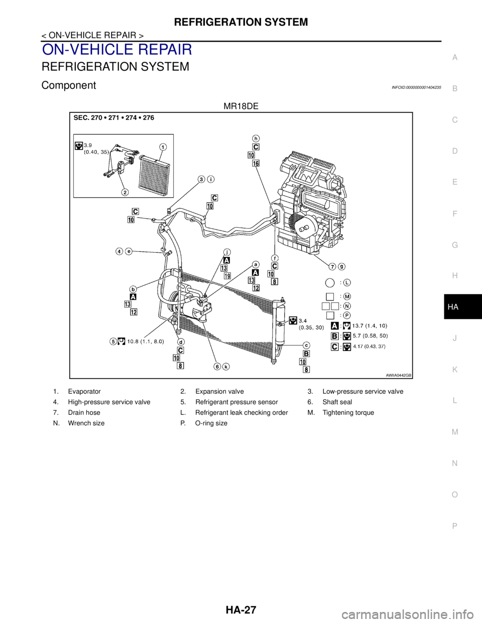
4. Perform the leak test from the high-pressure side (compressor discharge a to evaporator inlet f) to the
low-pressure side (evaporator drain hose g to shaft seal k). Refer to HA-27, "
Component". Perform a leak
check for the following areas carefully. Clean the component to be checked and move the leak detected
probe completely around the connection/component.
Compressor
Check the fitting of high- and low-pressure flexible hoses, relief valve and shaft seal.
Condenser
Check the fitting of high-pressure flexible hose and pipe, refrigerant pressure sensor.
Liquid tank
Check the refrigerant connection.
Service valves
Check all around the service valves. Ensure service valve caps are secured on the service valves (to
prevent leaks).
NOTE:
After removing A/C manifold gauge set from service valves, wipe any residue from valves to prevent any
false readings by leak detector.
Cooling unit (Evaporator)
With engine OFF, turn blower fan on “High” for at least 15 seconds to dissipate any refrigerant trace in
the cooling unit. Wait a minimum of 10 minutes accumulation time (refer to the manufacturer’s recom-
mended procedure for actual wait time) before inserting the leak detector probe into the drain hose.
Keep the probe inserted for at least 10 seconds. Use caution not to contaminate the probe tip with water
or dirt that may be in the drain hose.
5. If a leak detector detects a leak, verify at least once by blowing compressed air into area of suspected
leak, then repeat check as outlined above.
6. Do not stop when one leak is found. Continue to check for additional leaks at all system components.
If no leaks are found, perform steps 7-10.
7. Start engine.
8. Set the heater A/C control as follows;
a. A/C switch: ON
b. Mode control dial position: VENT (Ventilation)
c. Intake door lever position: Recirculation
d. Max. cold temperature
e. Fan speed: High
9. Run engine at 1,500 rpm for at least 2 minutes.
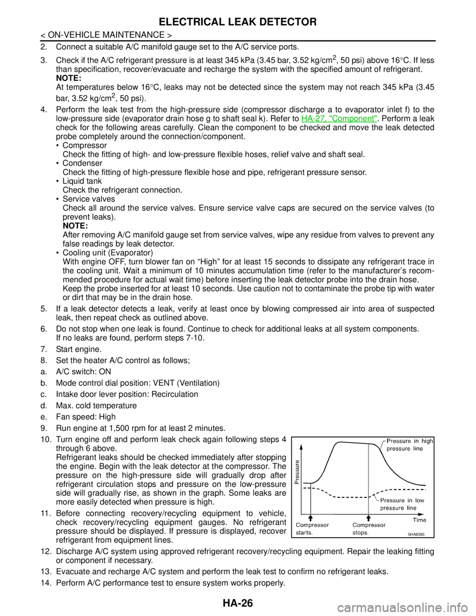
10. Turn engine off and perform leak check again following steps 4
through 6 above.
Refrigerant leaks should be checked immediately after stopping
the engine. Begin with the leak detector at the compressor. The
pressure on the high-pressure side will gradually drop after
refrigerant circulation stops and pressure on the low-pressure
side will gradually rise, as shown in the graph. Some leaks are
more easily detected when pressure is high.
11. Before connecting recovery/recycling equipment to vehicle,
check recovery/recycling equipment gauges. No refrigerant
pressure should be displayed. If pressure is displayed, recover
refrigerant from equipment lines.
12. Discharge A/C system using approved refrigerant recovery/recycling equipment. Repair the leaking fitting
or component if necessary.
13. Evacuate and recharge A/C system and perform the leak test to confirm no refrigerant leaks.
14. Perform A/C performance test to ensure system works properly.
SHA839E
Page 3309 of 5883
REFRIGERATION SYSTEM
HA-27
< ON-VEHICLE REPAIR >
C
D
E
F
G
H
J
K
L
MA
B
HA
N
O
P
ON-VEHICLE REPAIR
REFRIGERATION SYSTEM
ComponentINFOID:0000000001404235
MR18DE
AWIIA0442GB
1. Evaporator 2. Expansion valve 3. Low-pressure service valve
4. High-pressure service valve 5. Refrigerant pressure sensor 6. Shaft seal
7. Drain hose L. Refrigerant leak checking order M. Tightening torque
N. Wrench size P. O-ring size
Page 3310 of 5883
HA-28
< ON-VEHICLE REPAIR >
REFRIGERATION SYSTEM
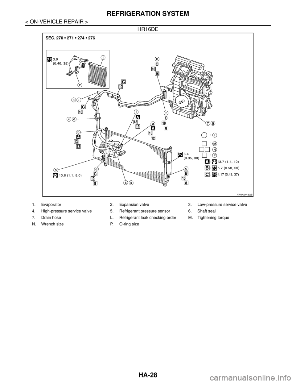
HR16DE
AWIIA0443GB
1. Evaporator 2. Expansion valve 3. Low-pressure service valve
4. High-pressure service valve 5. Refrigerant pressure sensor 6. Shaft seal
7. Drain hose L. Refrigerant leak checking order M. Tightening torque
N. Wrench size P. O-ring size
Page 3311 of 5883
REFRIGERATION SYSTEM
HA-29
< ON-VEHICLE REPAIR >
C
D
E
F
G
H
J
K
L
MA
B
HA
N
O
P
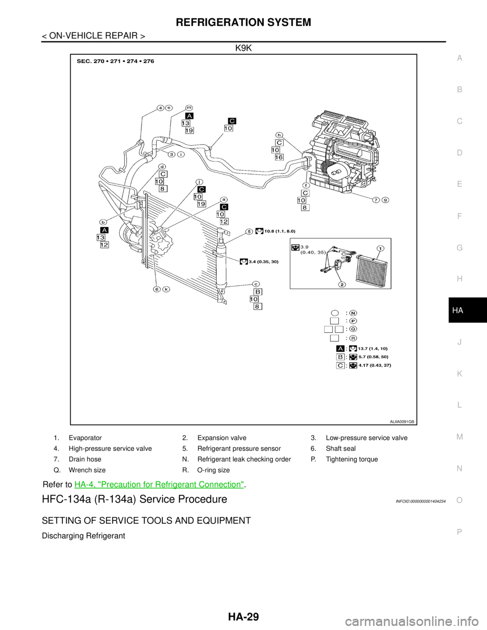
K9K
Refer to HA-4, "Precaution for Refrigerant Connection".
HFC-134a (R-134a) Service ProcedureINFOID:0000000001404234
SETTING OF SERVICE TOOLS AND EQUIPMENT
Discharging Refrigerant
ALIIA0091GB
1. Evaporator 2. Expansion valve 3. Low-pressure service valve
4. High-pressure service valve 5. Refrigerant pressure sensor 6. Shaft seal
7. Drain hose N. Refrigerant leak checking order P. Tightening torque
Q. Wrench size R. O-ring size
Page 3331 of 5883
EXPANSION VALVE
HA-49
< ON-VEHICLE REPAIR >
C
D
E
F
G
H
J
K
L
MA
B
HA
N
O
P
EXPANSION VALVE
Removal and Installation of Expansion Valve - MR18DE, HR16DE and K9K
INFOID:0000000001527645
REMOVAL
1. Use the recovery/recycling equipment to evacuate the refrigerant. Refer to HA-21, "HFC-134a (R-134a)
Service Procedure".
2. Remove cowl top cover. Refer to EXT-20, "
Removal and Installation".
3. Remove lower dash insulator.
4. Disconnect low-pressure flexible hose and high-pressure pipe from evaporator. Refer to HA-27, "
Compo-
nent".
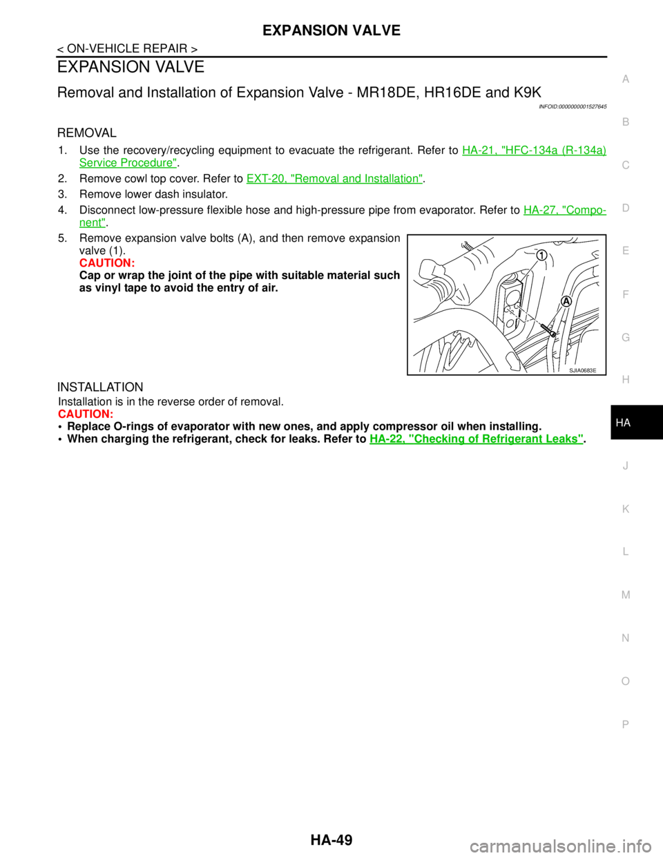
5. Remove expansion valve bolts (A), and then remove expansion
valve (1).
CAUTION:
Cap or wrap the joint of the pipe with suitable material such
as vinyl tape to avoid the entry of air.
INSTALLATION
Installation is in the reverse order of removal.
CAUTION:
Replace O-rings of evaporator with new ones, and apply compressor oil when installing.
When charging the refrigerant, check for leaks. Refer to HA-22, "
Checking of Refrigerant Leaks".
SJIA0683E
Page 3363 of 5883
![NISSAN TIIDA 2007 Service Repair Manual HAC-30
< COMPONENT DIAGNOSIS >[MANUAL AIR CONDITIONER]
INTAKE SENSOR
INTAKE SENSOR
Component InspectionINFOID:0000000001675415
COMPONENT DESCRIPTION
Intake Sensor
The intake sensor (1) is located on t NISSAN TIIDA 2007 Service Repair Manual HAC-30
< COMPONENT DIAGNOSIS >[MANUAL AIR CONDITIONER]
INTAKE SENSOR
INTAKE SENSOR
Component InspectionINFOID:0000000001675415
COMPONENT DESCRIPTION
Intake Sensor
The intake sensor (1) is located on t](/manual-img/5/57395/w960_57395-3362.png)
HAC-30
< COMPONENT DIAGNOSIS >[MANUAL AIR CONDITIONER]
INTAKE SENSOR
INTAKE SENSOR
Component InspectionINFOID:0000000001675415
COMPONENT DESCRIPTION
Intake Sensor
The intake sensor (1) is located on the A/C unit. It converts tempera-
ture of air after it passes through the evaporator (2) into a resistance
value which is then input to the BCM.
Intake Sensor Diagnosis ProcedureINFOID:0000000001675416
DIAGNOSTIC PROCEDURE FOR INTAKE SENSOR
SYMPTOM: Intake sensor circuit is open or shorted.
1.CHECK VOLTAGE BETWEEN INTAKE SENSOR AND GROUND
1. Turn ignition switch OFF.
2. Disconnect intake sensor connector.
3. Turn ignition switch ON.
4. Check voltage between intake sensor harness connector M42
terminal 1 and ground.
OK or NG
OK >> GO TO 2.
NG >> GO TO 4.
2.CHECK CIRCUIT CONTINUITY BETWEEN INTAKE SENSOR AND BCM
ZJIA0798J
AWIIA0452GB
Te r m i n a l s
Vo l ta g e
(Approx.) (+) (−)
Connector Terminal
Ground
Intake sensor: M42 1 5V
SJIA0825E
Page 3406 of 5883
![NISSAN TIIDA 2007 Service Repair Manual INSUFFICIENT COOLING
HAC-73
< SYMPTOM DIAGNOSIS >[MANUAL AIR CONDITIONER]
C
D
E
F
G
H
J
K
L
MA
B
HAC
N
O
P
INSUFFICIENT COOLING
Component Function CheckINFOID:0000000001547073
SYMPTOM: Insufficient co NISSAN TIIDA 2007 Service Repair Manual INSUFFICIENT COOLING
HAC-73
< SYMPTOM DIAGNOSIS >[MANUAL AIR CONDITIONER]
C
D
E
F
G
H
J
K
L
MA
B
HAC
N
O
P
INSUFFICIENT COOLING
Component Function CheckINFOID:0000000001547073
SYMPTOM: Insufficient co](/manual-img/5/57395/w960_57395-3405.png)
INSUFFICIENT COOLING
HAC-73
< SYMPTOM DIAGNOSIS >[MANUAL AIR CONDITIONER]
C
D
E
F
G
H
J
K
L
MA
B
HAC
N
O
P
INSUFFICIENT COOLING
Component Function CheckINFOID:0000000001547073
SYMPTOM: Insufficient cooling
INSPECTION FLOW
1.CONFIRM SYMPTOM BY PERFORMING OPERATIONAL CHECK - TEMPERATURE DECREASE
1. Turn temperature control dial counterclockwise to maximum cold position.
2. Check for cold air at discharge air outlets.
Can the symptom be duplicated?
YES >> GO TO 3.
NO >> GO TO 2.
2.CHECK FOR ANY SYMPTOMS
Perform a complete operational check for any symptoms. Refer to HAC-6, "
Operational Check".
Does another symptom exist?
YES >> Refer to HAC-5, "How to Perform Trouble Diagnosis For Quick and Accurate Repair".
NO >> System OK.
3.CHECK FOR SERVICE BULLETINS
Check for any service bulletins.
>> GO TO 4.
4.CHECK COMPRESSOR DRIVE BELT TENSION
Check compressor belt tension. Refer to EM-15, "
Checking" (HR16DE) or EM-142, "Checking Drive Belts"
(MR18DE), or EM-263, "Inspection and Adjustment" (K9K).
OK or NG
OK >> GO TO 5.
NG >> Adjust or replace compressor belt. Refer to EM-15, "
Checking" (HR16DE) or EM-142, "Checking
Drive Belts" (MR18DE), or EM-263, "Inspection and Adjustment" (K9K)
5.CHECK AIR MIX DOOR CABLE
Check and verify air mix door cable operation. Refer to XXXX AIR MIX DOOR CABLE ADJUST.
Does air mix door operate correctly?
YES >> GO TO 6.
NO >> Repair or replace as necessary.
6.CHECK COOLING FAN MOTOR OPERATION
Check and verify cooling fan motor for smooth operation. Refer to XX-XX, "*****".
Does cooling fan motor operate correctly?
YES >> GO TO 7.
NO >> Check cooling fan motor. Refer to XX-XX, "*****".
7.CHECK FOR EVAPORATOR FREEZE UP
Start engine and run A/C. Check for evaporator freeze up.
Does evaporator freeze up?
YES >> Perform performance test diagnoses. Refer to "PERFORMANCE TEST DIAGNOSIS".
NO >> GO TO 8.
8.CHECK REFRIGERANT PRESSURE
Check refrigerant pressure with manifold gauge connected. Refer to "Test Reading".
OK or NG
OK >> GO TO 9.
NG >> Perform performance test diagnoses. Refer to "PERFORMANCE TEST DIAGNOSIS".
Page 3411 of 5883
![NISSAN TIIDA 2007 Service Repair Manual HAC-78
< SYMPTOM DIAGNOSIS >[MANUAL AIR CONDITIONER]
INSUFFICIENT COOLING
High-pressure Side is Too High and Low-pressure Side is Too Low
High-pressure Side is Too Low and Low-pressure Side is Too Hig NISSAN TIIDA 2007 Service Repair Manual HAC-78
< SYMPTOM DIAGNOSIS >[MANUAL AIR CONDITIONER]
INSUFFICIENT COOLING
High-pressure Side is Too High and Low-pressure Side is Too Low
High-pressure Side is Too Low and Low-pressure Side is Too Hig](/manual-img/5/57395/w960_57395-3410.png)
HAC-78
< SYMPTOM DIAGNOSIS >[MANUAL AIR CONDITIONER]
INSUFFICIENT COOLING
High-pressure Side is Too High and Low-pressure Side is Too Low
High-pressure Side is Too Low and Low-pressure Side is Too High
Both High- and Low-pressure Sides are Too Low
Gauge indication Refrigerant cycle Probable cause Corrective action
Both high- and low-pressure
sides are too high.Pressure is reduced soon af-
ter water is splashed on con-
denser.Excessive refrigerant charge in refrig-
eration cycle.Reduce refrigerant until
specified pressure is ob-
tained.
Air suction by cooling fan is in-
sufficient.Insufficient condenser cooling perfor-
mance.
↓
1. Condenser fins are clogged.
2. Improper fan rotation of cooling
fan. Clean condenser.
Check and repair cooling
fan if necessary.
Low-pressure pipe is not
cold.
When compressor is
stopped high-pressure val-
ue quickly drops by approx-
imately 196 kPa (1.96 bar, 2
kg/cm
2 , 28 psi). It then de-
creases gradually thereaf-
ter.Poor heat exchange in condenser
(After compressor operation stops,
high-pressure decreases too slowly.).
↓
Air in refrigeration cycle.Evacuate repeatedly and
recharge system.
Engine tends to overheat. Engine cooling systems malfunction.Check and repair each en-
gine cooling system.
An area of the low-pressure
pipe is colder than areas
near the evaporator outlet.
Plates are sometimes cov-
ered with frost. Excessive liquid refrigerant on low-
pressure side.
Excessive refrigerant discharge
flow.
Expansion valve is open a little
compared with the specification.
↓
Improper expansion valve adjust-
ment.Replace expansion valve.
AC359A
Gauge indication Refrigerant cycle Probable cause Corrective action
High-pressure side is too high
and low-pressure side is too low.
Upper side of condenser and
high-pressure side are hot,
however, liquid tank is not so
hot.High-pressure tube or parts located
between compressor and condenser
are clogged or crushed. Check and repair or re-
place malfunctioning
parts.
Check oil for contami-
nation.
AC360A
Gauge indication Refrigerant cycle Probable cause Corrective action
High-pressure side is too low
and low-pressure side is too
high.High- and low-pressure sides
become equal soon after com-
pressor operation stops.Compressor pressure operation
is improper.
↓
Damaged inside compressor
packings.Replace compressor.
No temperature difference be-
tween high- and low-pressure
sides.Compressor pressure operation
is improper.
↓
Damaged inside compressor
packings.Replace compressor.
AC356A