2007 NISSAN TIIDA ecu work
[x] Cancel search: ecu workPage 5294 of 5883

TM-348
< FUNCTION DIAGNOSIS >[TYPE 2 (4AT: RE4F03B)]
DIAGNOSIS SYSTEM (TCM)
DIAGNOSIS SYSTEM (TCM)
CONSULT-III Function (TRANSMISSION)INFOID:0000000001714329
CONSULT-III can display each diagnostic item using the diagnostic test models shown following.
SELF-DIAGNOSTIC RESULT MODE
Operation Procedure
After performing TM-38, "Diagnosis Procedure without CONSULT-III", place check marks for results on the
XX-XX, "*****"
. Reference pages are provided following the items.
Display Items List
TCM diagnostic mode Description
WORK SUPPORTSupports inspections and adjustments. Commands are transmitted to the TCM for setting the status
suitable for required operation, input/output signals are received from the TCM and received data is
displayed.
SELF-DIAG RESULTS Displays TCM self-diagnosis results.
DATA MONITOR Displays TCM input/output data in real time.
CAN DIAG SUPPORT MNTR The result of transmit/receive diagnosis of CAN communication can be read.
ACTIVE TEST Operation of electrical loads can be checked by sending drive signal to them.
FUNCTION TEST Conducted by CONSULT-III instead of a technician to determine whether each system is “OK” or “NG”.
ECU PART NUMBER TCM part number can be read.
Items (CONSULT-III screen terms) Malfunction is detected when... Reference page
VHCL SPEED SEN-A/T TCM does not receive the proper voltage signal from the sensor.XX-XX, "*****"
VHCL SPEED SEN-MTR TCM does not receive the proper voltage signal from the sensor.XX-XX, "*****"
SHIFT SOLENOID/V A TCM detects an improper voltage drop when it tries to operate the sole-
noid valve.XX-XX, "*****"
SHIFT SOLENOID/V B TCM detects an improper voltage drop when it tries to operate the sole-
noid valve.XX-XX, "*****"
OVERRUN CLUTCH S/V TCM detects an improper voltage drop when it tries to operate the sole-
noid valve.XX-XX, "*****"
T/C CLUTCH SOL/V TCM detects an improper voltage drop when it tries to operate the sole-
noid valve.XX-XX, "*****"
BATT/FLUID TEMP SEN TCM receives an excessively low or high voltage from the sensor.XX-XX, "*****"
ENGINE SPEED SIG TCM does not receive the proper voltage signal from the ECM.XX-XX, "*****"
TURBINE SENSOR TCM does not receive proper voltage signal from sensor.XX-XX, "*****"
LINE PRESSURE S/V TCM detects an improper voltage drop when it tries to operate the sole-
noid valve.XX-XX, "*****"
CAN COMM CIRCUIT When malfunction is detected in CAN communication line.XX-XX, "*****"
A/T 1ST GR FNCTN A/T cannot be shifted to the 1st gear position even if electrical circuit is
good.XX-XX, "*****"
A/T 2ND GR FNCTN A/T cannot be shifted to the 2nd gear position even if electrical circuit is
good.XX-XX, "*****"
A/T 3RD GR FNCTN A/T cannot be shifted to the 3rd gear position even if electrical circuit is
good.XX-XX, "*****"
A/T 4TH GR FNCTN A/T cannot be shifted to the 4th gear position even if electrical circuit is
good.XX-XX, "*****"
A/T TCC S/V FNCTN A/T cannot perform lock-up even if electrical circuit is good.XX-XX, "*****"
CONTROL UNIT (RAM) TCM memory (RAM) is malfunctioning.XX-XX, "*****"
CONTROL UNIT (ROM) TCM memory (ROM) is malfunctioning.XX-XX, "*****"
Page 5372 of 5883

TM-426
< ECU DIAGNOSIS >[TYPE 2 (4AT: RE4F03B)]
TCM
Wiring Diagram - A/T CONTROL SYSTEM -
INFOID:0000000001714340
Fail-SafeINFOID:0000000001714341
The TCM has an electronic Fail-safe mode. This allows the vehicle to be driven even if a major electrical input/
output device circuit is damaged.
Under Fail-Safe, the vehicle always runs in third gear, even with a shift lever position of “1”, “2” or “D”. The cus-
tomer may complain of sluggish or poor acceleration.
Always follow TM-10, "
Work Flow".
ALDWA0057GB
Page 5412 of 5883

TM-466
< PRECAUTION >[TYPE 2 (4AT: RE4F03B)]
PRECAUTIONS
Be sure to turn the ignition switch OFF and disconnect battery negative cable from battery negative
terminal before any repair or inspection work. The open/short circuit of related switches, sensors,
solenoid valves, etc. will cause the MIL to light up.
Be sure to connect and lock the connectors securely after work. A loose (unlocked) connector will
cause the MIL to light up due to an open circuit. (Be sure the connectors are free from water, grease,
dirt, bent terminals, etc.)
Be sure to route and secure the harnesses properly after work. Interference of the harness with a
bracket, etc. may cause the MIL to light up due to a short circuit.
Be sure to erase the unnecessary malfunction information (repairs completed) from the TCM and
ECM before returning the vehicle to the customer.
PrecautionINFOID:0000000001723047
Before connecting or disconnecting the TCM harness connec-
tor, turn ignition switch OFF and disconnect the battery cable
from the negative terminal. Failure to do so may damage the
TCM. Because battery voltage is applied to TCM even if igni-
tion switch is turned off.
When connecting or disconnecting pin connectors into or
from TCM, take care not to damage pin terminals (bend or
break).
Make sure that there are not any bends or breaks on TCM pin
terminal, when connecting pin connectors.
Before replacing TCM, perform TCM input/output signal
inspection and make sure whether TCM functions properly or
not. (See page XX-XX, "*****"
.)
After performing each TROUBLE DIAGNOSIS, perform “DTC
(Diagnostic Trouble Code) Confirmation Procedure”.
The DTC should not be displayed in the “DTC Confirmation
Procedure” if the repair is completed.
Before proceeding with disassembly, thoroughly clean the outside
of the transaxle. It is important to prevent the internal parts from
becoming contaminated by dirt or other foreign matter.
Disassembly should be done in a clean work area.
Use lint-free cloth or towels for wiping parts clean. Common shop
rags can leave fibers that could interfere with the operation of the A/T.
Place disassembled parts in order for easier and proper assembly.
All parts should be carefully cleaned with a general purpose, non-flammable solvent before inspection or
reassembly.
Gaskets, seals and O-rings should be replaced any time the A/T is disassembled.
It is very important to perform functional tests whenever they are indicated.
The valve body contains precision parts and requires extreme care when parts are removed and serviced.
Place disassembled valve body parts in order for easier and proper assembly. Care will also prevent springs
and small parts from becoming scattered or lost.
Properly installed valves, sleeves, plugs, etc. will slide along bores in valve body under their own weight.
SEF289H
AAT470A
MEF040DA
Page 5622 of 5883

TM-676
< ON-VEHICLE REPAIR >[6MT: RS6F94R]
CONTROL LINKAGE
18. Remove the grommet and then remove the shift cable and select cable from the vehicle.
INSTALLATION
Installation is in the reverse order of removal.
Shift the control lever to the neutral position.
Securely assemble each cable and the selector lever and shifter lever.
Securely assemble each cable and the cable mounting bracket.
Securely assemble each cable and the control device assembly.
Make sure that the claws of grommet are in contact with the floor.
Be careful about the installation direction and push the control lever knob into the control lever.
CAUTION:
Never reuse control lever knob.
Tapping work for tapping bolt is not applied to new clutch housing. Do not perform tapping by other than
screwing tapping bolt because tapping is formed by screwing tapping bolt into clutch housing.
CAUTION:
Never reuse tapping bolt.
Install the select cable (the control device assembly side) with the following procedure.
1. While pulling the lock of the select cable in the direction of the
arrow shown, install the select cable to the control device
assembly.
2. Slide the lock (1) of the select cable in the direction of the arrow
as shown to pull up the stopper (2) of the select cable.
3. Install the end of the select cable to the pin of the control device
assembly.
4. Install the lever stopper pin (1) or a pin [3 mm (0.12 in) dia.] to
the control device assembly.
CAUTION:
Select cable cannot be adjusted accurately without a use of
a lever stopper pin or a pin [3 mm (0.12 in) dia.].
NOTE:
A lever stopper pin is not included in control device assembly.
Therefore, if the control device assembly is not replaced, pre-
pare a pin [3 mm (0.12 in) dia.].
5. Check that the control lever does not move in the direction of the
select. If it moves, repeat step 3.
6. Shift the control lever to 4th gear position.
JPDIC0067ZZ
JPDIC0064ZZ
JPDIC0069ZZ
Page 5816 of 5883
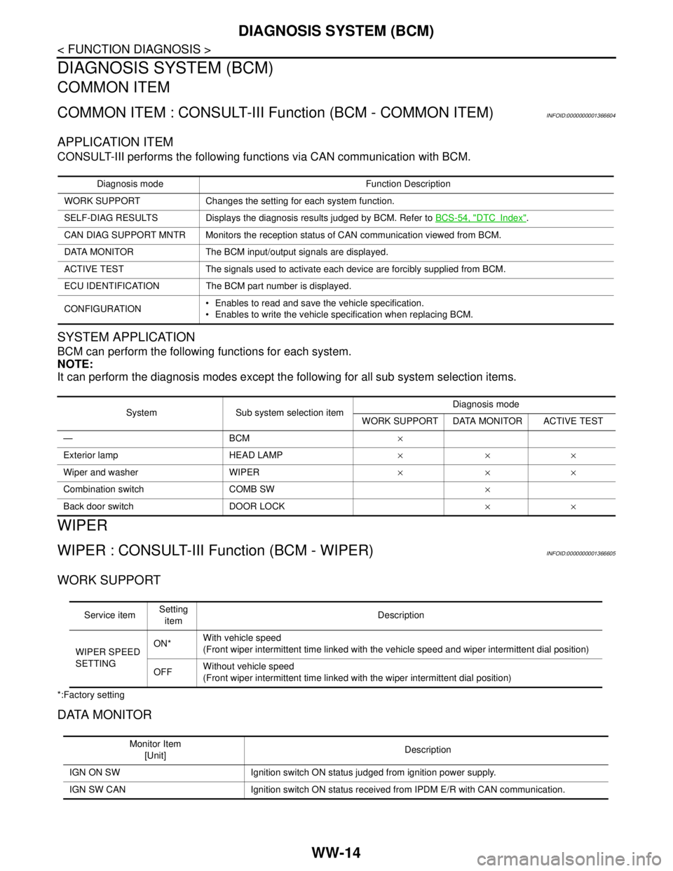
WW-14
< FUNCTION DIAGNOSIS >
DIAGNOSIS SYSTEM (BCM)
DIAGNOSIS SYSTEM (BCM)
COMMON ITEM
COMMON ITEM : CONSULT-III Function (BCM - COMMON ITEM)INFOID:0000000001366604
APPLICATION ITEM
CONSULT-III performs the following functions via CAN communication with BCM.
SYSTEM APPLICATION
BCM can perform the following functions for each system.
NOTE:
It can perform the diagnosis modes except the following for all sub system selection items.
WIPER
WIPER : CONSULT-III Function (BCM - WIPER)INFOID:0000000001366605
WORK SUPPORT
*:Factory setting
DATA MONITOR
Diagnosis mode Function Description
WORK SUPPORT Changes the setting for each system function.
SELF-DIAG RESULTS Displays the diagnosis results judged by BCM. Refer to BCS-54, "
DTCIndex".
CAN DIAG SUPPORT MNTR Monitors the reception status of CAN communication viewed from BCM.
DATA MONITOR The BCM input/output signals are displayed.
ACTIVE TEST The signals used to activate each device are forcibly supplied from BCM.
ECU IDENTIFICATION The BCM part number is displayed.
CONFIGURATION Enables to read and save the vehicle specification.
Enables to write the vehicle specification when replacing BCM.
System Sub system selection itemDiagnosis mode
WORK SUPPORT DATA MONITOR ACTIVE TEST
—BCM×
Exterior lamp HEAD LAMP×××
Wiper and washer WIPER×××
Combination switch COMB SW×
Back door switch DOOR LOCK××
Service itemSetting
itemDescription
WIPER SPEED
SETTINGON*With vehicle speed
(Front wiper intermittent time linked with the vehicle speed and wiper intermittent dial position)
OFFWithout vehicle speed
(Front wiper intermittent time linked with the wiper intermittent dial position)
Monitor Item
[Unit]Description
IGN ON SW Ignition switch ON status judged from ignition power supply.
IGN SW CAN Ignition switch ON status received from IPDM E/R with CAN communication.