2007 NISSAN QUEST ABS
[x] Cancel search: ABSPage 24 of 384
cDo not attach anything to the head re-
straint stalks. Doing so could impair
active head restraint function.
The head restraint moves forward utilizing the
force that the seatback receives from the occu-
pant in a rear-end collision. The movement of the
head restraint helps support the occupant’s head
by reducing its backward movement and helping
absorb some of the forces that may lead to whip-
lash type injuries.
Active head restraints are effective for collisions
at low to medium speeds in which it is said that
whiplash injury occurs most.
Active head restraints operate only in certain
rear-end collisions. After the collision, the head
restraints return to their original positions.
Properly adjust the active head restraints as de-
scribed in this section.
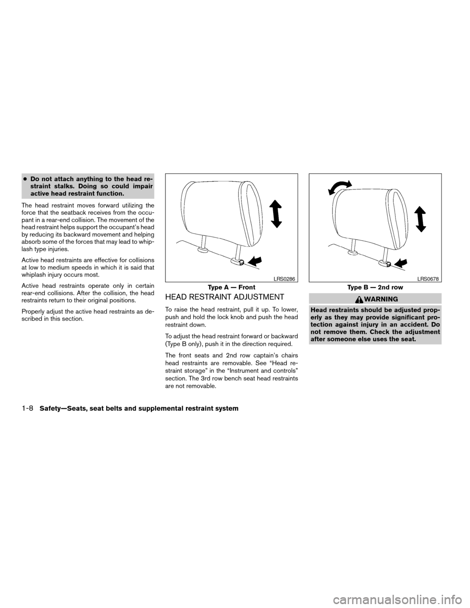
HEAD RESTRAINT ADJUSTMENT
To raise the head restraint, pull it up. To lower,
push and hold the lock knob and push the head
restraint down.
To adjust the head restraint forward or backward
(Type B only) , push it in the direction required.
The front seats and 2nd row captain’s chairs
head restraints are removable. See “Head re-
straint storage” in the “Instrument and controls”
section. The 3rd row bench seat head restraints
are not removable.
WARNING
Head restraints should be adjusted prop-
erly as they may provide significant pro-
tection against injury in an accident. Do
not remove them. Check the adjustment
after someone else uses the seat.
Type A — Front
LRS0286
Type B — 2nd row
LRS0678
1-8Safety—Seats, seat belts and supplemental restraint system
ZREVIEW COPYÐ2007 Quest(van)
Owners ManualÐUSA_English(nna)
02/24/06Ðdebbie
X
Page 251 of 384

5 Starting and driving
Precautions when starting and driving................5-2
Exhaust gas (carbon monoxide)..................5-2
Three-way catalyst..............................5-2
Tire pressure monitoring system (TPMS)
(for models without MichelinTPAXTtires
only)..........................................5-3
Tire pressure monitoring system (TPMS)
(for models with MichelinTPAXTtires only)........5-5
Avoiding collision and rollover....................5-7
Drinking alcohol/drugs and driving................5-7
Ignition switch.....................................5-8
Automatic transmission..........................5-8
Key positions..................................5-9
Nissan vehicle immobilizer system................5-9
Before starting the engine..........................5-9
Starting the engine...............................5-10
Driving the vehicle................................5-10
Automatic transmission.........................5-10
Parking brake....................................5-14
Cruise control....................................5-15
Precautions on cruise control...................5-15Cruise control operations.......................5-15
Break-in schedule................................5-16
Increasing fuel economy...........................5-17
Parking/parking on hills............................5-18
Power steering...................................5-19
Brake system....................................5-19
Brake precautions.............................5-19
Anti-lock braking system (ABS).................5-20
Traction control system (TCS)......................5-22
Vehicle dynamic control (VDC) system
(if so equipped)..................................5-23
Rear sonar system (if so equipped).................5-24
Cold weather driving..............................5-25
Freeing a frozen door lock......................5-25
Anti-freeze....................................5-25
Battery.......................................5-25
Draining of coolant water.......................5-25
Tire equipment................................5-25
Tire equipment................................5-26
Special winter equipment.......................5-26
Driving on snow or ice.........................5-26
ZREVIEW COPYÐ2007 Quest(van)
Owners ManualÐUSA_English(nna)
02/27/06Ðdebbie
X
Page 270 of 384
This procedure is described in the vehicle service
manual and can be performed by a NISSAN
dealer.
ANTI-LOCK BRAKING SYSTEM
(ABS)
The anti-lock braking system controls the brakes
so the wheels do not lock when braking abruptly
or when braking on slippery surfaces. The system
detects the rotation speed at each wheel and
varies the brake fluid pressure to prevent each
wheel from locking and sliding. By preventing
wheel lockup, the system helps the driver main-
tain steering control and helps to minimize swerv-
ing and spinning on slippery surfaces.
Using the system
Depress the brake pedal and hold it down.
WARNING
Do not pump the brake pedal. Doing so
may result in increased stopping
distances.
Normal operation
The anti-lock braking system does not operate at
speeds below3-6MPH(5-10km/h) . (The
speeds vary according to road conditions.)When driving, the anti-lock braking system con-
trols the wheels so they will not lock when brak-
ing abruptly or when braking on a slippery road.
Thus, steering control is increased and swerving
of the vehicle is decreased during emergency
braking. The system detects the wheel rotation
rate and electronically controls the pressure ap-
plied to each brake. Slight vibration on the brake
pedal accompanied by noise usually occurs while
the ABS system is operating. Such vibration and
noise encountered during abrupt braking is not a
problem, but indicates that the system is func-
tioning properly. However, the pulsation may in-
dicate that road conditions are hazardous and
extra care is required while driving.
Self-test feature
The anti-lock braking system consists of elec-
tronic sensors and hydraulic solenoids controlled
by a computer. The computer has a built-in diag-
nostic feature that tests the system each time you
start the engine and move the vehicle at a low
speed in forward or reverse. When the self-test
occurs, you may hear a “clunk” noise and/or feel a
pulsation in the brake pedal. This is normal and is
not an indication of any malfunction. If the com-
puter senses any malfunction, it switches the
anti-lock braking system off and turns on the ABS
brake warning light on the instrument panel. The
braking system then operates normally, but with-
out anti-lock assistance.If the light comes on during the self-test or while
driving, take the vehicle to a NISSAN dealer for
repair.
WARNING
cThe anti-lock braking system is a so-
phisticated device, but it cannot pre-
vent accidents resulting from careless
or dangerous driving techniques. It can
help maintain vehicle control during
braking on slippery surfaces, but re-
member that the stopping distance on
slippery surfaces will be longer than on
normal surfaces even with the anti-lock
braking system. Stopping distances
may also be longer on rough, gravel or
snow covered roads, or if you are using
tire chains. Tire type and condition may
also affect braking effectiveness. Al-
ways maintain a safe distance from the
vehicle in front of you. Ultimately, the
responsibility for safety of self and oth-
ers rests in the hands of the driver.
cTire type and condition of tires may also
affect braking effectiveness.
cWhen replacing tires, install the speci-
fied size of tires on all four wheels.
5-20Starting and driving
ZREVIEW COPYÐ2007 Quest(van)
Owners ManualÐUSA_English(nna)
02/27/06Ðdebbie
X
Page 271 of 384
cWhen installing a spare tire, make sure
it is the proper size and type as speci-
fied on the Tire and Loading Informa-
tion label. For tire placard location in-
formation, refer to “Tire and Loading
Information label” in the “Technical and
consumer information” section of this
manual.
cRefer to “Wheels and tires” in the
“Maintenance and do-it-yourself” sec-
tion of this manual.
Self-test feature
The anti-lock braking system consists of elec-
tronic sensors and hydraulic solenoids controlled
by a computer. The computer has a built-in diag-
nostic feature that tests the system each time you
start the engine and move the vehicle at a low
speed in forward or reverse. When the self-test
occurs, you may hear a “clunk” noise and/or feel a
pulsation in the brake pedal. This is normal and is
not an indication of any malfunction. If the com-
puter senses any malfunction, it switches the
anti-lock braking system off and turns on the ABS
brake warning light on the instrument panel. The
braking system then operates normally, but with-
out anti-lock assistance.If the light comes on during the self-test or while
driving, take the vehicle to a NISSAN dealer for
repair.
WARNING
cThe anti-lock braking system is a so-
phisticated device, but it cannot pre-
vent accidents resulting from careless
or dangerous driving techniques. It can
help maintain vehicle control during
braking on slippery surfaces, but re-
member that the stopping distance on
slippery surfaces will be longer than on
normal surfaces even with the anti-lock
braking system. Stopping distances
may also be longer on rough, gravel or
snow covered roads, or if you are using
tire chains. Tire type and condition may
also affect braking effectiveness. Al-
ways maintain a safe distance from the
vehicle in front of you. Ultimately, the
responsibility for safety of self and oth-
ers rests in the hands of the driver.
cTire type and condition of tires may also
affect braking effectiveness.
cWhen replacing tires, install the speci-
fied size of tires on all four wheels.cWhen installing a spare tire, make sure
it is the proper size and type as speci-
fied on the Tire and Loading Informa-
tion label. For tire placard location in-
formation, refer to “Tire and Loading
Information label” in the “Technical and
consumer information” section of this
manual.
cRefer to “Wheels and tires” in the
“Maintenance and do-it-yourself” sec-
tion of this manual.
Starting and driving5-21
ZREVIEW COPYÐ2007 Quest(van)
Owners ManualÐUSA_English(nna)
02/27/06Ðdebbie
X
Page 273 of 384
When accelerating or driving on slippery sur-
faces, the tires may spin or slide. With the Vehicle
Dynamic Control (VDC) system, sensors detect
these movements and control the braking and
engine output to help improve vehicle stability.
cWhen the vehicle dynamic control (VDC)
system is operating, the slip indicator in the
instrument panel blinks.
cIf the slip indicator blinks, the road condi-
tions are slippery. Be sure to adjust your
speed and driving to these conditions. See
“Slip indicator light”, and “Vehicle dynamic
control (VDC) off indicator light” in the “In-
struments and controls” section.
cIndicator light
If malfunction occurs in the system,
the
andindicator lights come
on in the instrument panel.
As long as these indicator lights are on, the
traction control function is canceled.
If the vehicle is operated with the vehicle dynamic
control system OFF using the VDC OFF switch,
VDC functions will be turned off. The VDC sys-
tem will still try to transfer power from a slipping
drive wheel to one with more traction when the
VDC system switch is OFF. The Slip indicator will
flash if wheel spin is detected. The ABS will still
operate with the VDC system off.When the VDC system is operating, you may feel
a pulsation in the brake pedal and hear a noise or
vibration from under the hood. This is normal and
indicates that the VDC system is working prop-
erly.
The computer has a built in diagnostic feature
that tests the system each time you start the
engine and move the vehicle forward or in reverse
at a slow speed. When the self-test occurs, you
may hear a clunk noise and/or feel a pulsation in
the brake pedal. This is normal and is not an
indication of a malfunction.
WARNING
cThe vehicle dynamic control system is
designed to help improve driving stabil-
ity but does not prevent accidents due
to abrupt steering operation at high
speeds or by careless or dangerous
driving techniques. Reduce vehicle
speed and be especially careful when
driving and cornering on slippery sur-
faces and always drive carefully.cIf brake related parts such as brake
pads, rotors and calipers are not stan-
dard equipment or are extremely dete-
riorated, the vehicle dynamic control
system may not operate properly and
the vehicle dynamic control off indica-
tor light may come on.
cDo not modify the vehicle’s suspension.
If suspension parts such as shock ab-
sorbers, struts, springs, stabilizer bars
and bushings are not NISSAN approved
for your vehicle or are extremely dete-
riorated the vehicle dynamic control
system may not operate properly. This
could adversely affect vehicle handling
performance, and the VDC OFF indica-
tor light may come on.
cWhen driving on extremely inclined sur-
faces such as higher banked corners,
the vehicle dynamic control system may
not operate properly and the VDC OFF
indicator light may come on. Do not
drive on these types of roads.
cWhen driving on an unstable surface
such as a turntable, ferry, elevator or
ramp, the vehicle dynamic control off
indicator light may illuminate. This is
not a malfunction. Restart the engine
after driving onto a stable surface
VEHICLE DYNAMIC CONTROL (VDC)
SYSTEM (if so equipped)
Starting and driving5-23
ZREVIEW COPYÐ2007 Quest(van)
Owners ManualÐUSA_English(nna)
02/27/06Ðdebbie
X
Page 359 of 384
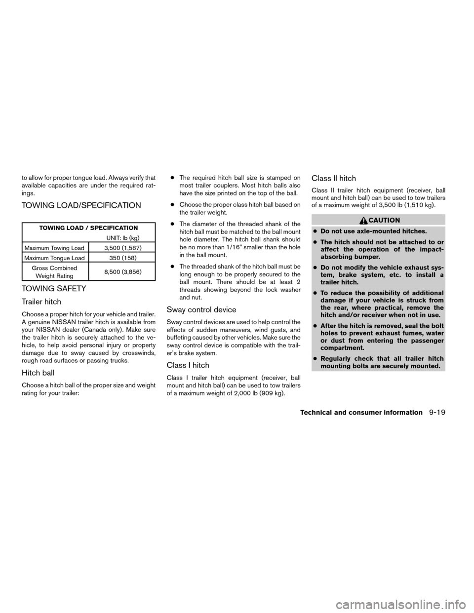
to allow for proper tongue load. Always verify that
available capacities are under the required rat-
ings.
TOWING LOAD/SPECIFICATION
TOWING LOAD / SPECIFICATION
UNIT: lb (kg)
Maximum Towing Load 3,500 (1,587)
Maximum Tongue Load 350 (158)
Gross Combined
Weight Rating8,500 (3,856)
TOWING SAFETY
Trailer hitch
Choose a proper hitch for your vehicle and trailer.
A genuine NISSAN trailer hitch is available from
your NISSAN dealer (Canada only) . Make sure
the trailer hitch is securely attached to the ve-
hicle, to help avoid personal injury or property
damage due to sway caused by crosswinds,
rough road surfaces or passing trucks.
Hitch ball
Choose a hitch ball of the proper size and weight
rating for your trailer:cThe required hitch ball size is stamped on
most trailer couplers. Most hitch balls also
have the size printed on the top of the ball.
cChoose the proper class hitch ball based on
the trailer weight.
cThe diameter of the threaded shank of the
hitch ball must be matched to the ball mount
hole diameter. The hitch ball shank should
be no more than 1/16” smaller than the hole
in the ball mount.
cThe threaded shank of the hitch ball must be
long enough to be properly secured to the
ball mount. There should be at least 2
threads showing beyond the lock washer
and nut.
Sway control device
Sway control devices are used to help control the
effects of sudden maneuvers, wind gusts, and
buffeting caused by other vehicles. Make sure the
sway control device is compatible with the trail-
er’s brake system.
Class I hitch
Class I trailer hitch equipment (receiver, ball
mount and hitch ball) can be used to tow trailers
of a maximum weight of 2,000 lb (909 kg) .
Class II hitch
Class II trailer hitch equipment (receiver, ball
mount and hitch ball) can be used to tow trailers
of a maximum weight of 3,500 lb (1,510 kg) .
CAUTION
cDo not use axle-mounted hitches.
cThe hitch should not be attached to or
affect the operation of the impact-
absorbing bumper.
cDo not modify the vehicle exhaust sys-
tem, brake system, etc. to install a
trailer hitch.
cTo reduce the possibility of additional
damage if your vehicle is struck from
the rear, where practical, remove the
hitch and/or receiver when not in use.
cAfter the hitch is removed, seal the bolt
holes to prevent exhaust fumes, water
or dust from entering the passenger
compartment.
cRegularly check that all trailer hitch
mounting bolts are securely mounted.
Technical and consumer information9-19
ZREVIEW COPYÐ2007 Quest(van)
Owners ManualÐUSA_English(nna)
02/27/06Ðdebbie
X
Page 369 of 384

10 Index
A
Active head restraint...............1-7
Adjusting pedal position............3-21
Air bag (See supplemental restraint
system).....................1-51
Air bag system
Front (See supplemental front impact
air bag system)...............1-58
Side and curtain (See supplemental side
air bag and curtain side-impact air bag
system)...................1-62
Air bag warning labels.............1-65
Air bag warning light...........1-65, 2-11
Air cleaner housing filter............8-16
Air conditioner
Air conditioner operation..........4-34
Air conditioner service...........4-43
Air conditioner specification label.....9-11
Air conditioner system refrigerant and
oil recommendations.............9-6
Heater and air conditioner
controls................4-31, 4-40
Rear seat air conditioner..........4-42
Servicing air conditioner..........4-43
Air flow charts..................4-35
Alarm system
(See vehicle security system).........2-14
Anchor point locations.............1-30
Antenna.....................4-61
Anti-lock brake warning light..........2-8Anti-lock braking system (ABS)........5-20
Audible reminders................2-14
Audio system..................4-43
AM-FM-SAT radio with compact disc
(CD) changer................4-51
AM-FM-SAT radio with compact disc
(CD) player.................4-51
Compact Disc (CD) changer.......4-56
Compact disc (CD) player.........4-55
MP3 display..................4-6
Radio....................4-43
Rear audio controls.............4-60
Steering wheel audio control switch. . . .4-59
Autolight switch.................2-20
Automatic
Automatic drive positioner.........3-25
Automatic power window switch.....2-40
Automatic transmission position indicator
light.....................2-11
Driving with automatic transmission. . . .5-10
Transmission selector lever lock
release....................5-12
Automatic anti-glare inside mirror.......3-23
Average speed..................4-4
B
Back button................4-7, 4-18
Battery......................8-13
Charge warning light.............2-8
Before starting the engine............5-9Belts (See drive belts).............8-15
Bench seat adjustment (3rd row). . . .1-7, 1-12
BluetoothThands-free phone system.....4-72
Booster seats..................1-47
Brake
Anti-lock braking system (ABS)......5-20
Brake fluid..................8-12
Brake light (See stop light).........8-25
Brake system................5-19
Brake warning light..............2-8
Brake wear indicators........2-14, 8-20
Parking brake check............8-20
Parking brake operation..........5-14
Self-adjusting brakes............8-20
Brake pedal...................8-20
Break-in schedule................5-16
Brightness control
Instrument panel..............2-22
Brightness/contrast button. . . .4-6, 4-16, 4-28
Bulb check/instrument panel..........2-7
Bulb replacement................8-25
C
Capacities and recommended
fuel/lubricants...................9-2
Captain’s chair adjustment (2nd row)......1-6
Car phone or CB radio.............4-72
Cargo (See vehicle loading information) . . .9-12
CD care and cleaning.............4-58
CD changer (See audio system)........4-56
ZREVIEW COPYÐ2007 Quest(van)
Owners ManualÐUSA_English(nna)
02/27/06Ðdebbie
X