2007 NISSAN QUEST key
[x] Cancel search: keyPage 151 of 384

Reverse:
The power lift gate will reverse direction immedi-
ately during power open or power close if the
keyfob, overhead console or rear pillar switch is
pressed. A chime will sound to announce the
reversal.
Auto Reverse:
If an obstacle is detected during power open or
power close, a warning chime will sound and the
lift gate will reverse direction and return to the full
open or full close position. If a second obstacle is
detected, the lift gate motion will stop and the
drive motor will disengage. The lift gate will enter
manual mode.
A pinch strip is mounted on each side of the lift
gate. If an obstacle is detected by a pinch strip
during power close, the lift gate will reverse di-
rection and return to the full open position.
NOTE:
If the pinch strip is damaged or removed,
the power close function will not operate.WARNING
There are some small distances immedi-
ately before the closed position which
cannot be detected. Make sure that all
passengers have their hands, etc., inside
the vehicle before closing the lift gate.
Manual Mode:
If power operation is not available, the lift gate
may be operated manually. Power operation may
not be available if the main ON/OFF switch is in
the OFF position, if multiple obstacles have been
detected in a single power cycle, or if battery
voltage is low.
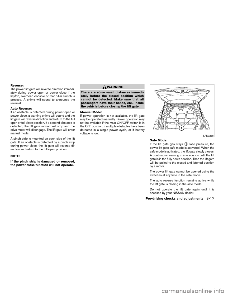
Safe Mode:
If the lift gate gas stays
s1lose pressure, the
power lift gate safe mode is activated. When the
safe mode is activated, the lift gate slowly closes.
A continuous warning chime sounds until the lift
gate is in the fully down position. Then the lift gate
will be pulled to the closed and latched position
by a motor.
The power lift gate cannot be opened using the
switches at any time in the safe mode.
The auto reverse function remains active while
the lift gate is closing in the safe mode.
Do not operate the lift gate again until it is
checked by your NISSAN dealer.
LPD0238
Pre-driving checks and adjustments3-17
ZREVIEW COPYÐ2007 Quest(van)
Owners ManualÐUSA_English(nna)
02/27/06Ðdebbie
X
Page 152 of 384

CAUTION
cIf the power lift gate does not stay open
or if the lift gate unexpectedly closes at
any time while a continuous warning
chime sounds, do not operate the lift
gate. There may be a pressure loss in
one or both of the lift gate gas stays.
Have the lift gate inspected by a
NISSAN dealer.
cDo not activate the power lift gate if one
or both of the lift gate gas stays are
removed. Damage to the lift gate or
power lift gate mechanisms may occur.
LIFT GATE RELEASE
WARNING
cAlways be sure the lift gate has been
closed securely to prevent it from open-
ing while driving.
cDo not drive with the lift gate open. This
could allow dangerous exhaust gases
to be drawn into the vehicle. See “Ex-
haust gas” in the “Starting and driving”
section of this manual.
CAUTION
cIf the power lift gate does not stay open
or if the lift gate unexpectedly closes at
any time while a continuous warning
chime sounds, do not operate the lift
gate. There may be a pressure loss in
one or both of the lift gate gas stays.
Have the lift gate inspected by a
NISSAN dealer.
cDo not activate the power lift gate if one
or both of the lift gate gas stays are
removed. Damage to the lift gate or
power lift gate mechanisms may occur.
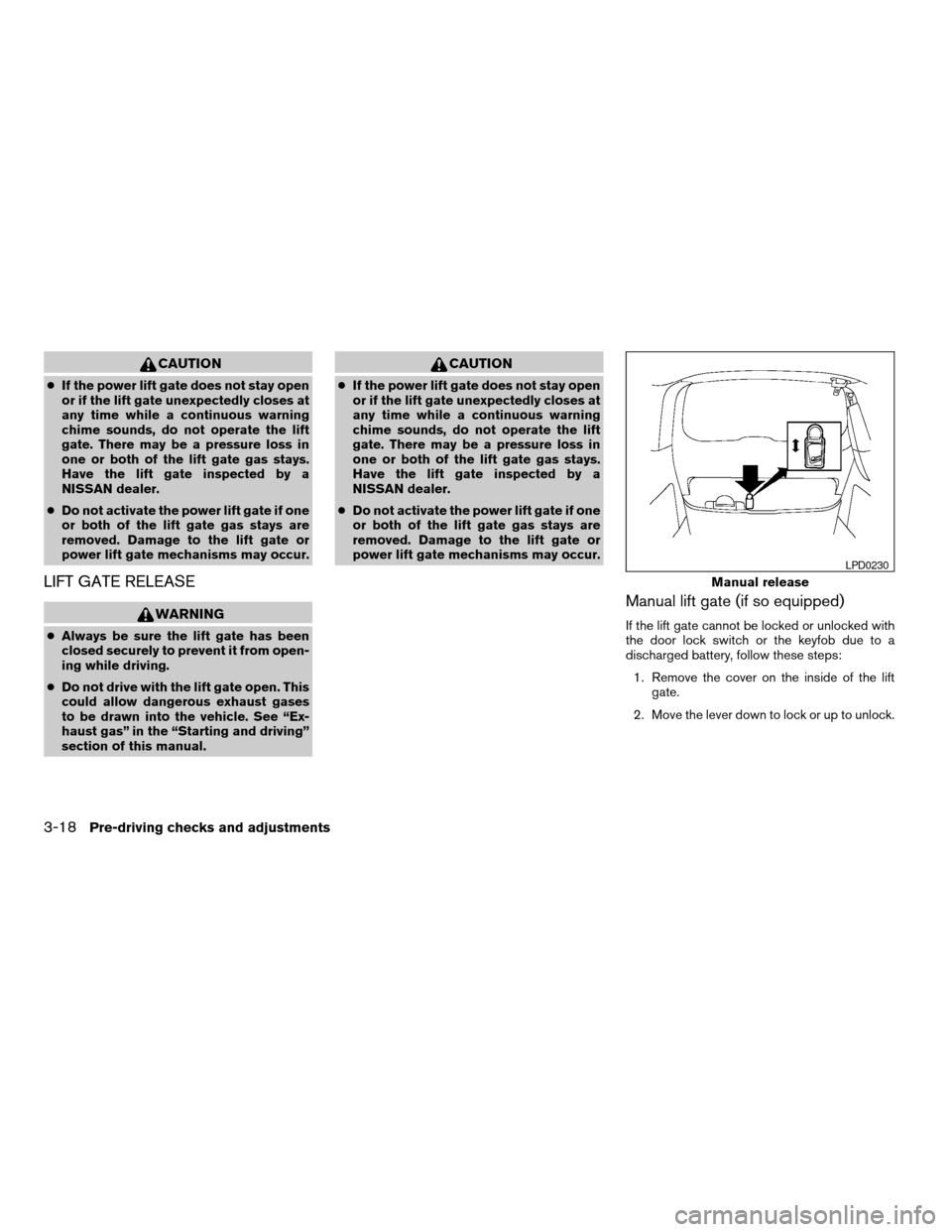
Manual lift gate (if so equipped)
If the lift gate cannot be locked or unlocked with
the door lock switch or the keyfob due to a
discharged battery, follow these steps:
1. Remove the cover on the inside of the lift
gate.
2. Move the lever down to lock or up to unlock.
Manual release
LPD0230
3-18Pre-driving checks and adjustments
ZREVIEW COPYÐ2007 Quest(van)
Owners ManualÐUSA_English(nna)
02/27/06Ðdebbie
X
Page 153 of 384

Power lift gate (if so equipped)
If the lift gate cannot be opened with the door
lock switch or keyfob due to a discharged battery,
follow these steps:
1. Remove the cover on the inside of the lift
gate.
2. Move the lever up to open the lift gate.
OPENER OPERATION
The fuel-filler door release is located on the driv-
er’s door. To open the fuel-filler door, push the
release. To lock, close the fuel-filler door se-
curely.
FUEL-FILLER CAP
The fuel-filler cap is a ratcheting type. Turn the
cap counterclockwise to remove. To tighten, turn
the cap clockwise until ratcheting clicks are
heard.
Put the fuel-filler cap on the cap holder
s1while
refueling.
Power release
LPD0236WPD0341LPD0232
FUEL-FILLER DOOR
Pre-driving checks and adjustments3-19
ZREVIEW COPYÐ2007 Quest(van)
Owners ManualÐUSA_English(nna)
02/27/06Ðdebbie
X
Page 160 of 384

MEMORY STORAGE FUNCTION
Two positions for the driver’s seat, accelerator
and brake pedals, and outside mirrors can be
stored in the automatic drive positioner memory.
Follow these procedures to use the memory sys-
tem.
1. Set the automatic transmission selector le-
ver to the P (Park) position.
2. Turn the ignition ON.3. Adjust the driver’s seat, accelerator and
brake pedals, and outside mirrors to the
desired positions by manually operating
each adjusting switch. For additional infor-
mation, see “Seats” in the “Safety—Seats,
seat belts and supplemental restraint sys-
tem” section and “Pedal position adjust-
ment” and “Outside mirrors” earlier in this
section.
During this step, do not turn the ignition to
any position other than ON.
4. Push the SET switch and, within 5 seconds,
push the memory switch (1 or 2) fully for at
least 1 second.
The indicator light for the pushed memory
switch will come on and stay on for approxi-
mately 5 seconds after pushing the switch.
After the indicator light goes off, the se-
lected positions are stored in the selected
memory (1 or 2) .
If a new memory is stored in the same memory
switch, the previous memory will be deleted.
Linking a keyfob to a stored memory
position
Each keyfob can be linked to a stored memory
position (memory switch 1 or 2) with the follow-
ing procedure.1. Follow the steps for storing a memory posi-
tion.
2. While the indicator light for the memory
switch being set is illuminated for 5 sec-
onds, press the
button on the keyfob.
The indicator light will blink. After the indica-
tor light goes off, the keyfob is linked to that
memory setting.
With the key removed from the ignition switch,
press the
button on the keyfob. The driv-
er’s seat, accelerator and brake pedals, and out-
side mirrors will move to the memorized position.
NOTE:
If a new memory position is saved to the
memory switch, the keyfob automatically
re-links.
Procedure for storing the outside
mirror positions for best visibility when
backing up
An outside mirror position for backing up can be
stored for each memory switch (1 and 2) .
1. Set the parking brake.
2. Turn the ignition ON. (Do not start the en-
gine.)
WPD0347
3-26Pre-driving checks and adjustments
ZREVIEW COPYÐ2007 Quest(van)
Owners ManualÐUSA_English(nna)
02/27/06Ðdebbie
X
Page 161 of 384

3. Push the memory switch 1 or 2 fully for at
least 1 second to operate the automatic
drive positioner.
4. Turn the outside mirror control switch to L
(left) .
5. Depress the brake pedal.
6. Move the automatic transmission shift lever
to R (Reverse) .
7. Adjust the mirror to the desired viewing po-
sition for backing up by operating the out-
side mirror control switch.
8. Push the SET switch and, within 5 seconds,
push the memory switch 1 or 2 selected in
step 3 fully for at least 1 second.
cThe indicator light for the pushed memory
switch will come on and stay on for approxi-
mately 5 seconds after pushing the switch.
After the indicator light goes off, the se-
lected mirror position is stored in the se-
lected memory (1 or 2) .
9. Turn the outside mirror control switch to R
(right) . Repeat the above procedure to ad-
just the right mirror position and store in the
selected memory.
cWhen the driver’s seat, accelerator and
brake pedals, and outside mirrors are not in
the memorized position, the outside mirror
will move with the initial tilt-down angle.Confirming memory storage
cTurn the ignition ON and push the SET
switch. If the main memory has not been
stored, the indicator light will come on for
approximately 0.5 seconds. When the
memory has stored the position, the indica-
tor light will stay on for approximately 5 sec-
onds.
cIf the battery cable is disconnected, or if the
fuse opens, the memory storage function will
be canceled and must be restarted before a
stored memory position can be set again.
Drive the vehicle over 25 MPH (40 km/h) to
restart the memory storage function. You
can also restart the memory storage function
using the following procedure.
1. Connect the battery cable or replace the
fuse.
2. Open and close the driver’s door more than
two times with the ignition key in the LOCK
position.
Once the memory storage function has been
restarted, you can store a memory position.
See “Memory storage function” earlier in this
section.
Selecting the memorized position
Set the automatic transmission selector lever to
the P (Park) position, then:
cWithin 45 seconds of opening the driver’s
door, push the memory switch (1 or 2) fully
for at least 1 second, or
cTurn the ignition switch to the ON position
and push the memory switch (1 or 2) fully for
at least 1 second.
The driver’s seat, accelerator and brake pedals,
and outside mirrors will move to the memorized
position with the indicator light blinking, and then
the light will stay on for approximately 5 seconds.
ENTRY/EXIT FUNCTION
This system is designed so that the driver’s seat
will automatically move when the automatic
transmission selector lever is in the P (Park)
position. This allows the driver to get into and out
of the driver’s seat more easily.
The driver’s seat will slide backward:
cWhen the key is removed from the ignition
switch and the driver’s door is opened.
cWhen the driver’s door is opened with the
key turned to LOCK.
Pre-driving checks and adjustments3-27
ZREVIEW COPYÐ2007 Quest(van)
Owners ManualÐUSA_English(nna)
02/27/06Ðdebbie
X
Page 162 of 384

cWhen the key is turned from ACC to LOCK
with the driver’s door open.
The driver’s seat will return to previous position:
cWhen the key is inserted into the ignition
switch and the driver’s door is closed.
cWhen the driver’s door is closed with the key
turned to LOCK.
cWhen the key is turned from ACC to ON
while the automatic transmission selector
lever is in the P (Park) position.
The entry/exit function can be adjusted or can-
celed. See “Vehicle electronic systems” in the
“Display screen, heater, air conditioner, audio
and phone systems” section of this manual.
Restarting the entry/exit function
If the battery cable is disconnected or if the fuse
opens, the entry/exit function will be disabled.
Drive the vehicle over 25 MPH (40 km/h) to
restart the entry/exit function. You can also restart
the entry/exit function using the following proce-
dure.
1. Connect the battery cable or replace the
fuse.
2. Open and close the driver’s door more than
two times with the ignition key in the LOCK
position.The entry/exit function should now work properly.
SYSTEM OPERATION
The automatic drive positioner system will not
work or will stop operating under the following
conditions:
cWhen the vehicle speed is above 4 MPH (7
km/h) .
cWhen any of the memory switches are
pushed while the automatic drive positioner
is operating.
cWhen the adjusting switch for the driver’s
seat is turned on while the automatic drive
positioner is operating.
cWhen the memory switch (1 or 2) is not
pushed and held for at least 1 second.
cWhen the seat has been already moved to
the memorized position.
cWhen no seat position is stored in the
memory switch.
cWhen the automatic transmission selector
lever is moved from P (Park) to any other
position.
cWhen the driver’s door remains open more
than 45 seconds and the ignition switch is
not in the ON position.The automatic drive positioner system can be
adjusted and canceled. See “Vehicle electronic
systems” in the “Display screen, heater, air con-
ditioner, audio and phone systems” section of
this manual.
3-28Pre-driving checks and adjustments
ZREVIEW COPYÐ2007 Quest(van)
Owners ManualÐUSA_English(nna)
02/27/06Ðdebbie
X
Page 169 of 384

In case of low tire pressure, a message “LOW
PRESSURE” or “CHECK ALL TIRES” is dis-
played on the screen:
LOW PRESSURE — CHECK ALL TIRES.
WARNING
cWhen a spare tire is mounted or a wheel
is replaced, tire pressure will not be
indicated, the Tire Pressure Monitoring
System (TPMS) will not function and
the low tire pressure warning light will
flash. Contact your NISSAN dealer as
soon as possible for tire replacement
and/or system resetting.
cReplacing tires with those not originally
specified by NISSAN could affect the
proper operation of the TPMS.
HOW TO USE THE SETTING
BUTTON
Pressing the SETTING button will change the
settings menu as follows:
Backlight!Day Mode Brightness!Night
Mode Brightness!Clock Adjust HOURS!
Clock Adjust MINUTES!Units!Lang!MP3
Disp Type (if so equipped)!Audio or OFF!
Backlight
Backlight
To turn off the screen, select “OFF” of the Back-
light mode by pressing the TUNE button.
The message “Press SETTINGS to resume” will
display for approximately 5 seconds then the
screen will turn off.
To turn on the screen, press the SETTING button
and select “ON” by pressing the TUNE button.
When any button besides SETTING is pressed
with the screen off, the screen turns on for further
operation. The screen will turn off automatically
after the operation is finished.
Day mode brightness
The brightness of the screen during the day can
be changed by pressing the TUNE button.
For additional information, see “
button”
later in this section.
Night mode brightness
The brightness of the screen during the night can
be changed by pressing the TUNE button.
For additional information, see “
button”
later in this section.
Clock operation
The digital clock displays time when the ignition
key is in ACC or ON.
If the power supply is disconnected, the
clock will not indicate the correct time.
Readjust the time.
Clock adjust hours
Press the SETTING button until Clock Adjust
HOURS is shown in the display. Press the TUNE
button up or down to adjust the hour.
Clock adjust minutes
Press the SETTING button again Clock Adjust
Minutes is shown in the display. Press the TUNE
button up or down to adjust the minutes.
To exit the clock adjustment, press the SETTING
button repeatedly. The screen will return to the
audio display if the audio is on. If the audio is not
on, the screen will return to a blank display.
Units
To change the units press the TUNE button to
select “ENGLISH” or “METRIC”.
Unit: US — MI, °F, MPG
Metric — km, °C, L/100 km
Display screen, heater, air conditioner, audio and phone systems4-5
ZREVIEW COPYÐ2007 Quest(van)
Owners ManualÐUSA_English(nna)
02/27/06Ðdebbie
X
Page 171 of 384

1. TRIP button (P. 4-8)
2. BACK (previous) button (P. 4-7)
3. Joystick and ENTER button (P. 4-7)
4.
brightness control button (P.
4-16)5. SETTING button (P. 4-11)
If you use the system with the engine not
running (ignition ON or ACC) for a long
time, it will use up all the battery power,
and the engine will not start.Reference symbols:
ENTER button — This is a button on the control
panel. By pressing this button you can select the
item or perform this action.
“Display” key — This is a select key on the screen.
By selecting this key you can proceed to the next
function.
HOW TO USE THE JOYSTICK AND
ENTER BUTTON
Use the joystick to choose an item on the display
screen. Move the joystick up, down, left or right to
highlight an item. Then press the ENTER button
to select the item or perform the action.
HOW TO USE THE BACK BUTTON
This button has two functions.
cGo back to the previous display (cancel) .
If you press the BACK button during setup, the
setup will be canceled and/or the display will
return to the previous screen.
cFinish setup.
In some screens pressing the BACK button ac-
cepts the changes made during setup.
Display screen without navigation
LHA0621
CONTROL PANEL BUTTONS —
COLOR SCREEN WITHOUT
NAVIGATION SYSTEM
Display screen, heater, air conditioner, audio and phone systems4-7
ZREVIEW COPYÐ2007 Quest(van)
Owners ManualÐUSA_English(nna)
02/27/06Ðdebbie
X