2007 NISSAN NOTE panel
[x] Cancel search: panelPage 62 of 235

5. When the vehicle’s interior has warmed-up, or
before you leave the vehicle, be sure to turn the
seat heater system off.
CAUTION
•Do not use the seat heater system for a long
period of time when the engine is not running,
otherwise the battery could run down.
•Do not put anything on the seat that insulates
the heat, such as a blanket, cushion, seat
cover, etc. Otherwise, the seat may overheat.
•Do not place anything hard or heavy on the
seat or pierce it with a pin or similar object.
This may damage the heater.
•Any liquid spilled on a heated seat should be
removed immediately with a dry cloth.
•When cleaning the seat, never use benzine,
thinner or any similar materials.
•If any abnormalities are found or the heating
does not operate, turn off the switch and have
the system checked by a NISSAN dealer or
qualified workshop.1.Power outlet
A.Front of the vehicle
The 12V (120 W) power outlet
j1 provides a high
output electrical power supply to operate devices
such as:
•pocket computer games
•personal stereo
•fans
CAUTION
•This power outlet is not designed for use with
a cigarette lighter unit.
•Use this power outlet with the engine running
(do not use for extended period of time with
the engine stopped or idling).
•When not in use, ensure that the cap is in-
serted. Do not allow water to contact the out-
let.
NIC1060Z
Front centre console
NIC1061Z
Rear centre console (where fitted)
NIC1485
Luggage compartment side panel (where fitted)
POWER OUTLET
2-20Instruments and controls
Page 63 of 235

•Before inserting or disconnecting a plug, be
sure to turn off the power switch of the elec-
trical accessory being used or the Acc power
of the vehicle.
•Fully push the plug in. If insufficient contact is
made, the plug may overheat or the respec-
tive fuse may blow.
WARNING
Take care as the power outlet and plug may be
hot during or immediately after use.
GLOVE BOX
WARNING
•The glove box storage should not be used
while driving so that full attention may be given
to the driving operation.
•Keep the glove box lid closed while driving to
prevent injury in an accident or a sudden stop.
The under side storage pocket
jA provides an eas-
ily accessible storage space. To access the glove
box, press the lock release button
j1.
Glove box air flow control dial
(where fitted)
CAUTION
•Do not put any objects that can melt in the
glove box compartment as it may damage the
compartment inner side.
•Do not leave any plastic objects in the glove
box compartment. They may be deformed.
•Do not put jewellery such as rings, earrings,
etc. in the glove box compartment, as the heat
may deform them.
The glove box compartment provides an adjustable
air flow control dial in order to keep beverages
chilled or warm. Turn the vent anticlockwise
j2to
provide full heating/cooling and turn clockwisej1
to close the outlet. The heating/cooling function set-
ting is monitored by the heater and air conditioning
control panel. See “Heater and air conditioner
operation” in the “4. Heater and air conditioner, and
audio system” section for further details on passen-
ger compartment air control setting.
NIC1066Z
NIC1072Z
Glove box compartment
STORAGE
Instruments and controls2-21
Page 66 of 235
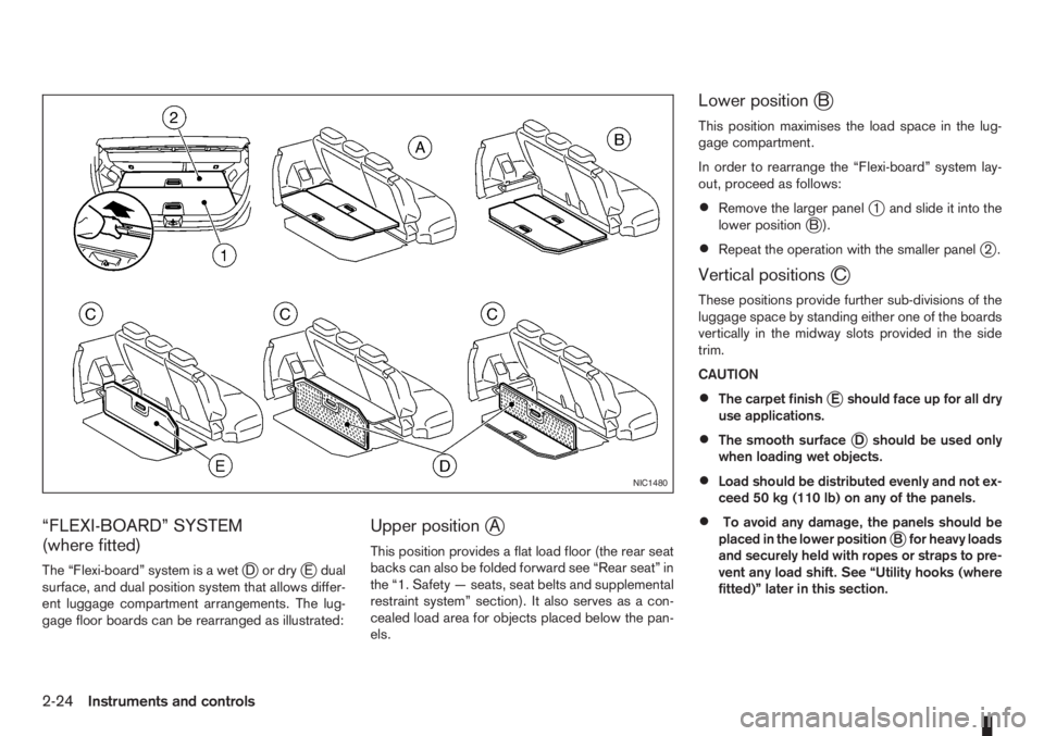
“FLEXI-BOARD” SYSTEM
(where fitted)
The “Flexi-board” system is a wetjDordryjE dual
surface, and dual position system that allows differ-
ent luggage compartment arrangements. The lug-
gage floor boards can be rearranged as illustrated:
Upper positionjA
This position provides a flat load floor (the rear seat
backs can also be folded forward see “Rear seat” in
the “1. Safety — seats, seat belts and supplemental
restraint system” section). It also serves as a con-
cealed load area for objects placed below the pan-
els.
Lower positionjB
This position maximises the load space in the lug-
gage compartment.
In order to rearrange the “Flexi-board” system lay-
out, proceed as follows:
•Remove the larger panelj1 and slide it into the
lower positionjB).
•Repeat the operation with the smaller panelj2.
Vertical positionsjC
These positions provide further sub-divisions of the
luggage space by standing either one of the boards
vertically in the midway slots provided in the side
trim.
CAUTION
•The carpet finishjE should face up for all dry
use applications.
•The smooth surfacejD should be used only
when loading wet objects.
•Load should be distributed evenly and not ex-
ceed 50 kg (110 lb) on any of the panels.
•To avoid any damage, the panels should be
placed in the lower positionjB for heavy loads
and securely held with ropes or straps to pre-
vent any load shift. See “Utility hooks (where
fitted)” later in this section.
NIC1480
2-24Instruments and controls
Page 67 of 235
WARNING
Always secure cargo with ropes or straps to help
prevent it from sliding or shifting. Do not place
cargo higher than the seatbacks. In a sudden
stop or collision, unsecured cargo could cause
personal injury.
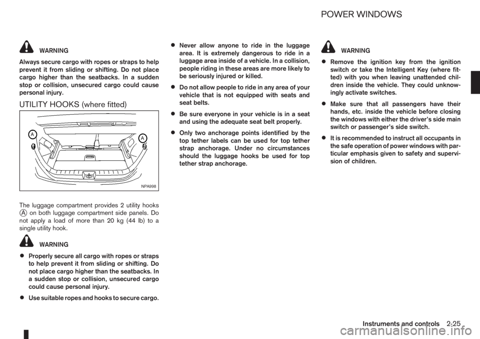
UTILITY HOOKS (where fitted)
The luggage compartment provides 2 utility hooksjA on both luggage compartment side panels. Do
notapplyaloadofmorethan20kg(44lb)toa
single utility hook.
WARNING
•Properly secure all cargo with ropes or straps
to help prevent it from sliding or shifting. Do
not place cargo higher than the seatbacks. In
a sudden stop or collision, unsecured cargo
could cause personal injury.
•Use suitable ropes and hooks to secure cargo.
•Never allow anyone to ride in the luggage
area. It is extremely dangerous to ride in a
luggage area inside of a vehicle. In a collision,
people riding in these areas are more likely to
be seriously injured or killed.
•Do not allow people to ride in any area of your
vehicle that is not equipped with seats and
seat belts.
•Be sure everyone in your vehicle is in a seat
and using the adequate seat belt properly.
•Only two anchorage points identified by the
top tether labels can be used for top tether
strap anchorage. Under no circumstances
should the luggage hooks be used for top
tether strap anchorage.
WARNING
•Remove the ignition key from the ignition
switch or take the Intelligent Key (where fit-
ted) with you when leaving unattended chil-
dren inside the vehicle. They could unknow-
ingly activate switches.
•Make sure that all passengers have their
hands, etc. inside the vehicle before closing
the windows with either the driver’s side main
switch or passenger’s side switch.
•It is recommended to instruct all occupants in
the safe operation of power windows with par-
ticular emphasis given to safety and supervi-
sion of children.
NPA998
POWER WINDOWS
Instruments and controls2-25
Page 68 of 235

1.Driver’s side window switch
2.Front passenger side window switch
3.Rear right passenger side window switch
(where fitted)
4.Rear left passenger side window switch
(where fitted)
5.Rear window lock switchNote that these illustrations are for LHD models.
DRIVER’S SIDE MAIN SWITCH
The driver’s side control panel is equipped with the
switchj2,j3andj4 to open or close the passen-
gers’ windows.
To open a window, push the switch and hold it
down. To close a window, pull the switch and hold
it up. To stop the opening or closing function at any
time, simply release the switch.
Locking passenger’s windows
Dependant on the vehicle specifications, when the
window lock buttonj5 is depressed either:
•the rear passenger window switches are dis-
abled; or
•the front and rear passenger window switches
are disabled.
Push it again to cancel the window lock function.
PASSENGER’S SIDE SWITCH
To open a window, push the switch and hold it
down. To close a window, pull the switch and hold
it up. To stop the opening or closing function at any
time, simply release the switch.
AUTOMATIC OPERATION
To fully open the driver’s side window, press the
window switchj1 down to the second detent and
release; it does not need to be held. The window
automatically opens all the way. To stop the win-
dow, lift the switch up while the window is opening.To fully close the driver’s side window, pull the
switch
j1 up to the second detent (where fitted)
and release it; it does not need to be held. The win-
dow automatically closes all the way. To stop the
window, press the switch
j1 down while the win-
dow is closing.
WARNING
Make sure that no passenger is obstructing the
driver’s side window opening when closing with
the driver’s side auto (A) power window switch.
See “Battery” in the “8. Maintenance and
do-it-yourself” section for reinitialisation procedure
after battery reconnection.
Auto reverse function (for driver’s
window equipped with automatic closing
function)
If the control unit detects something caught in the
driver’s window as it moves up, the window will be
immediately lowered.
The auto reverse function can be activated when the
driver’s window is closed by automatic operation
when the ignition key is in the ON position.
CAUTION
Depending on the environment or driving condi-
tions, the auto reverse function may be activated
if an impact or load similar to something being
caught in the window occurs.
NIC1067Z
Driver’s side main switch
NIC1068Z
Passenger’s side switch
2-26Instruments and controls
Page 78 of 235

lock button (central door lock equipped mod-
els), the indicator lightj3 remains illuminated
and the door unlocks.
•When the power door lock switch is moved to
the lock positionj1 while the driver’s door is
open and the integrated Intelligent Keyfob
(where fitted) is left inside the vehicle, all
doors unlock as the driver’s door is closed
and the buzzer sounds (central door lock
equipped models and Super Lock equipped
models). This is to prevent from locking the
vehicle while the Intelligent Key has been left
inside the vehicle.
Super Lock equipped models
Operating the power door lock switch located on
the centre console will lockj1 or unlockj2all
doors (the indicator lightj3 comes on when all
doors are locked). However, when the Super Lock
is set, it is not possible to unlock the doors with the
power door lock switch
j2 . Note that a chime will
sound and the doors will not lock if the power door
lock switch is pressed when a passenger door is
open, even if the driver’s door is closed.
In order to lock all doors without activating the Su-
per Lock system, open the driver’s door, move the
power door lock switch to the lock position
j1and
close the door.
CAUTION
Note that the above operation will not be pos-sible with a key in the ignition switch or when the
Intelligent Key is left inside the vehicle; a chime
will then sound in order to draw your attention
and the vehicle unlocks.
1.Lock position
2.Unlock position
A.Front of the vehicle
CHILD SAFETY REAR DOOR LOCK
Child safety locking helps prevent doors from being
opened accidentally. This mechanism is especially
handy when small children are in the vehicle.
When the lever is in the lock position
j1 , the rear
door can only be opened from the outside.
Set the lock lever in position
j2 in order to disable
the child safety rear door lock mechanism.
BACK DOOR LOCK
The power door lock system allows you to lock or
unlock all doors including the back door.
The back door can be manually released from the
outside when the vehicle is not locked by operating
the microswitch located on the back door under-
side.
NOTE
The back door cannot be opened from the out-
side when the power door lock switch is acti-
vated. An audible warning is heard when the
microswitch located on the back door underside
is operated.
To close, lower and push down the back door se-
curely.NPA735Z
Rear door side panel
NPA725Z
3-8Pre-driving checks and adjustments
Page 80 of 235
there is a 10 second time slot to start the engine
after the ignition is turned off. See your NISSAN
dealer for NATS service as soon as possible.
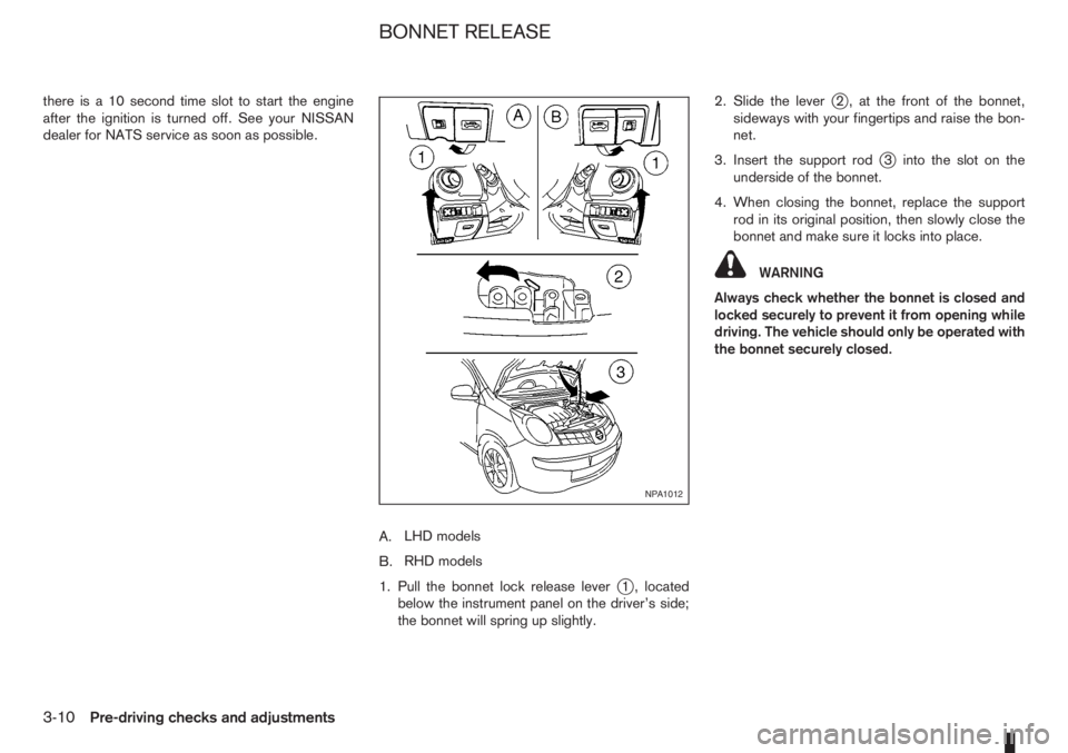
A.LHD models
B.RHD models
1. Pull the bonnet lock release lever
j1 , located
below the instrument panel on the driver’s side;
the bonnet will spring up slightly.2. Slide the lever
j2 , at the front of the bonnet,
sideways with your fingertips and raise the bon-
net.
3. Insert the support rod
j3 into the slot on the
underside of the bonnet.
4. When closing the bonnet, replace the support
rod in its original position, then slowly close the
bonnet and make sure it locks into place.
WARNING
Always check whether the bonnet is closed and
locked securely to prevent it from opening while
driving. The vehicle should only be operated with
the bonnet securely closed.
NPA1012
BONNET RELEASE
3-10Pre-driving checks and adjustments
Page 138 of 235

Accelerator downshift – In the D (Drive)
position
For rapid passing or driving uphill, fully depress the
accelerator pedal to the floor. This shifts the trans-
mission down into a lower gear, depending on the
vehicle speed.
A.RHD models
B.LHD models
Overdrive switch
ON: For normal driving, push the overdrive
switchto“ON
” with the selector lever in
the D (Drive) position. The transmission is
shifted up into OVERDRIVE as the vehicle
speed increases.
The overdrive will not engage until the engine
has warmed up.
OFF: For driving up and down long slopes where
engine braking is necessary, push the over-
drive switch “OFF
”. The overdrive off in-dicator light
in the instrument panel
illuminates.
When cruising at low speeds or climbing a
gentle slope, you may feel an uncomfortable
shift shock as the transmission shifts in and
out of the overdrive position repeatedly. In
this case, push the overdrive switch to turn
the Overdrive “OFF”.
When driving conditions change, push the overdrive
switch to turn the overdrive “ON”. The overdrive off
indicator light
in the instrument panel will turn
off.
Remember not to drive at high speeds for extended
periods of time with the overdrive “OFF”. This re-
duces fuel economy.
A.RHD models
B.LHD models
Shift lock release
If the battery is discharged, the selector lever can-
not be moved from the P (Park) position even with
the brake pedal depressed and the ignition switch in
the ON position.
To move the selector lever, push the shift lock re-
lease button
j1 (as illustrated) and press the selec-
tor lever buttonj2 . It is now possible to move the
selector lever to the N (Neutral) position.
For your safety, make sure the handbrake is applied
and the brake pedal is depressed during the opera-
tion.
If there is any problem moving the lever out of the P
(Park) position, have a NISSAN dealer or qualified
workshop to check the automatic transmission sys-
tem as soon as possible.
Fail-safe
When the Fail-safe operation occurs, the automatic
transmission will be locked in the third gear.
If the vehicle is driven under extreme conditions,
such as excessive wheel spinning and subse-
quent hard braking, the Fail-safe system may be
activated. This will occur even if all electrical cir-
cuits are functioning properly. In this case, turn
the ignition switch “OFF” and wait for 3 seconds.
Then turn the key back to the ON position. The
vehicle should return to its normal operating con-
dition. If it does not return to its normal operating
condition have your NISSAN dealer or qualified
NSD309Z
NSD310Z
5-14Starting and driving