Page 4 of 345
Table of
Contents
Illustrated table of contentsSafety — seats, seat belts and supplemental
restraint systemInstruments and controlsPre-driving checks and adjustmentsDisplay screen, heater, air conditioner and audio
systemsStarting and drivingIn case of emergencyAppearance and careMaintenance and do-it-yourselfTechnical and consumer informationIndex
�
06.7.5/Z50-D/V5.0
�
Page 10 of 345

1. Headlight, fog light* and turn signal switch
(P.2-22)
2. Trip odometer reset button (P.2-4)
3. Instrument brightness control switch
(P.2-26)
4. Meters/gauges (P.2-3)
5. Windshield (P.2-20)/rear window (P.2-21)
wiper and washer switch
6. Hazard warning flasher switch (P.2-27)
7. Center ventilator (P.4-21)
8. Audio control (P.4-27)
9. Display (P.4-2, P.4-11)/clock (P.4-4, P4-18)
10. Rear window defroster and Heated outside
mirror* switch (P.2-22)
11. Display screen control (P.4-2, P4-11)
and/or Navigation system*1
12. Passenger supplemental air bag (P.1-41)
13. Side ventilator (P.4-21)
14. Headlight aiming control switch* (P.2-25)
15. Vehicle Dynamic Control (VDC) OFF
switch* (P.2-29) or Headlight aiming con-
trol* (P.2-25)
16. Steering switch for audio control* (P.4-43)
17. Fuse box cover (P.8-21)
18. Tilting steering wheel lock lever (P.3-28)
19. Driver supplemental air bag (P.1-41)/Horn
(P.2-28)
20. Cruise control main/set switch (P.5-22)
21. Ignition switch/steering lock (P.5-9)
(P.5-10)
22. Heater/air conditioner control (P.4-23)
SSI0176
INSTRUMENT PANEL
Illustrated table of contents
0-5
�
06.7.5/Z50-D/V5.0
�
Page 75 of 345

1. Headlight, fog light* and turn signal switch
2. Trip odometer reset button
3. Instrument brightness control switch
4. Meters/gauges
5. Windshield/rear window wiper and washer
switch
6. Hazard warning flasher switch
7. Center ventilator
8. Audio control
9. Display/clock
10. Rear window defroster and Heated outside
mirror* switch
11. Display screen control and/or Navigation
system*1
12. Passenger supplemental air bag
13. Side ventilator
14. Headlight aiming control switch*
15. Vehicle Dynamic Control (VDC) OFF
switch* or Headlight aiming control*
16. Steering switch for audio control*
17. Fuse box cover
18. Tilting steering wheel lock lever
19. Driver supplemental air bag/Horn
20. Cruise control main/set switch
21. Ignition switch/steering lock
22. Heater/air conditioner control
23. Coin box
24. Outside mirror remote control
25. Cellular phone holder
26. AWD lock switch (AWD models)
27. Heated seat switch*
28. Power outlet cover
29. Glove box
*: if so equipped
SSI0176
INSTRUMENT PANEL2-2
Instruments and controls
�
06.7.5/Z50-D/V5.0
�
Page 77 of 345

SPEEDOMETER AND ODOMETER
SpeedometerThe speedometer indicates vehicle speed.Odometer/Twin trip odometerThe odometer
�1/twin trip odometer
�2
are
displayed when the ignition switch is in the ON
position.
The odometer records the total distance the
vehicle has been driven.
The twin trip odometer records the distance of
individual trips.Changing the display:
Pushing the reset button
�3
located on the left
side of the meter panel changes the display as
follows:
TRIP A→TRIP B→TRIP A
Resetting the trip odometer:
Pushing the reset button for more than 1 second
resets the trip odometer to zero.
Elapsed time, driving distance and average
speed information is also available. Refer to
“How to use the TRIP button” in the “4. Display
screen, heater, air conditioner and audio sys-
tems” section later in this manual.
TACHOMETERThe tachometer indicates engine speed in revo-
lutions per minute (rpm).
Do not rev engine into red zone
�A.
CAUTION
When engine speed approaches the red
zone, shift to a higher gear. Operating
the engine in the red zone may cause
serious engine damage.
SIC3032
SIC3033
2-4
Instruments and controls
�
06.7.5/Z50-D/V5.0
�
Page 97 of 345

The autolight system can turn on the headlights
automatically when it is dark and turn off the
headlights when it is light, and keep the head-
lights on for up to 45 seconds after you turn the
ignition switch to the OFF position and open any
door then close all the doors. The headlight off
time can be adjusted on the system setting
display. See the “4. Display screen, heater, air
conditioner and audio system” section.
If the ignition switch is turned OFF and one of
the doors is opened and this condition is con-
tinued, the headlights remain ON for 5 minutes.
Be sure not to put anything on top of the
photo sensor
�A
located on the top left-
hand side of the instrument panel. The
photo sensor controls the autolight; if it is
covered, the photo sensor reacts as if it is
dark and the headlights will illuminate.
Headlight beam select
�1To select the low beam, put the lever in the
neutral position as shown.
�2To select the high beam, push the lever
forward while the switch is in the
po-
sition. Pull it back to select the low beam.
�3Pulling the lever toward you will flash the
headlight high beam.
SIC2052
SIC3293
2-24
Instruments and controls
�
06.7.5/Z50-D/V5.0
�
Page 101 of 345

�Do not use the hazard warning flash-
ers while moving on the highway un-
less unusual circumstances force you
to drive so slowly that your vehicle
might become a hazard to other traf-
fic.
�Turn signals do not work when the
hazard warning flasher lights are on.
The flasher will operate with the ignition switch in
any position.
To sound the horn, push the center pad upper
area of the steering wheel.
WARNING
Do not disassemble the horn. Doing so
could affect proper operation of the
supplemental front air bag system. Tam-
pering with the supplemental front air
bag system may result in serious per-
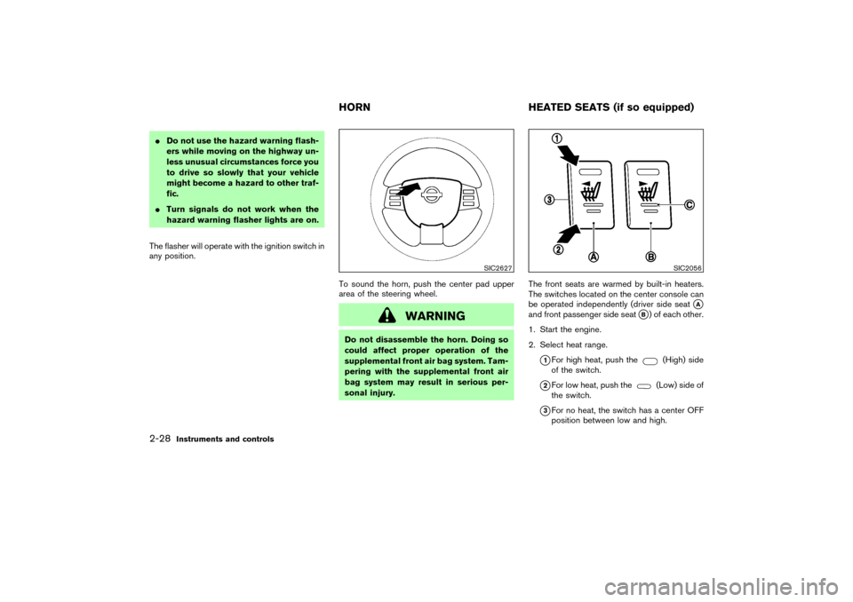
sonal injury.The front seats are warmed by built-in heaters.
The switches located on the center console can
be operated independently (driver side seat
�A
and front passenger side seat
�B) of each other.
1. Start the engine.
2. Select heat range.
�1For high heat, push the
(High) side
of the switch.
�2For low heat, push the
(Low) side of
the switch.
�3For no heat, the switch has a center OFF
position between low and high.
SIC2627
SIC2056
HORNHEATED SEATS (if so equipped)
2-28
Instruments and controls
�
06.7.5/Z50-D/V5.0
�
Page 102 of 345

The indicator light in the switch
�C
will
illuminate when low or high is selected.
The heater is controlled by a thermostat,
automatically turning the heater on and off.
The indicator light will remain on as long as
the switch is on.
3. When the vehicle’s interior is warmed, or
before you leave the vehicle, be sure to turn
the switch to the off position (center)
�3.
CAUTION
�The battery could run down if the
seat heater is operated while the en-
gine is not running.
�Do not use the seat heater for ex-
tended periods or when no one is
using the seat.
�Do not put anything on the seat
which insulates heat, such as a blan-
ket, cushion, seat cover, etc. Other-
wise, the seat may become over-
heated.
�Do not place anything hard or heavy
on the seat or pierce it with a pin orsimilar object. This may result in
damage to the heater.
�Any liquid spilled on the heated seat
should be removed immediately with
a dry cloth.
�When cleaning the seat, never use
gasoline, benzine, thinner, or any
similar materials.
�If any abnormalities are found or the
heated seat does not operate, turn
the switch off and have the system
checked by a NISSAN dealer.
The vehicle should be driven with the Vehicle
Dynamic Control (VDC) system ON for most
driving conditions.
If the vehicle is stuck in mud or snow, the VDC
system reduces the engine output to reduce
wheel spin. The engine speed will be reduced
even if the accelerator is depressed to the floor.
If maximum engine power is needed to free a
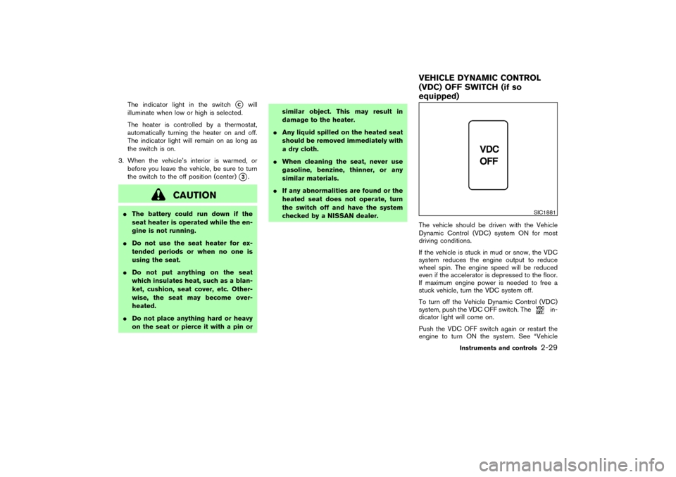
stuck vehicle, turn the VDC system off.
To turn off the Vehicle Dynamic Control (VDC)
system, push the VDC OFF switch. The
in-
dicator light will come on.
Push the VDC OFF switch again or restart the
engine to turn ON the system. See “Vehicle
SIC1881
VEHICLE DYNAMIC CONTROL
(VDC) OFF SWITCH (if so
equipped)
Instruments and controls
2-29
�
06.7.5/Z50-D/V5.0
�
Page 127 of 345

fuel-filler door. Unlock simulation can be
changed. See the “4. Display screen, heater,
air conditioner and audio system” section.
Opening and closing front windowsTurn the driver’s door key to the unlock position
and hold for about 1 second, the front windows
will begin to lower.
To stop opening, turn the key to the neutral
position.
To close the front windows with the door key
cylinder, turn the key to the lock position and
hold for about 1 second.
To stop closing, turn the key to the neutral
position.
LOCKING WITH INSIDE LOCK
KNOBTo individually lock the doors, move the inside
lock knobto the LOCK position
�1, then close
the door.
To unlock, move the inside lock knobup to the
UNLOCK position
�2.
When locking the door without a key, be
sure not to leave the key inside the vehicle.
LOCKING WITH POWER DOOR
LOCK SWITCHOperating the lock-unlock switch will lock or
unlock all doors. (driver and front passenger
sides)
To lock the doors, push the power door lock
switch located on the driver’s or front passen-
ger’s armrest to the lock position
�1
with the
driver’s or front passenger’s door open, then
close the door.
When locking the door this way, be certain
not to leave the key inside the vehicle.
SPA1814
SPA2320
3-4
Pre-driving checks and adjustments
�
06.7.5/Z50-D/V5.0
�