Page 2428 of 2896

MTC-16
REFRIGERATION SYSTEM
Revision: June 20062007 Versa
REFRIGERATION SYSTEMPFP:KA990
Refrigerant CycleEJS00576
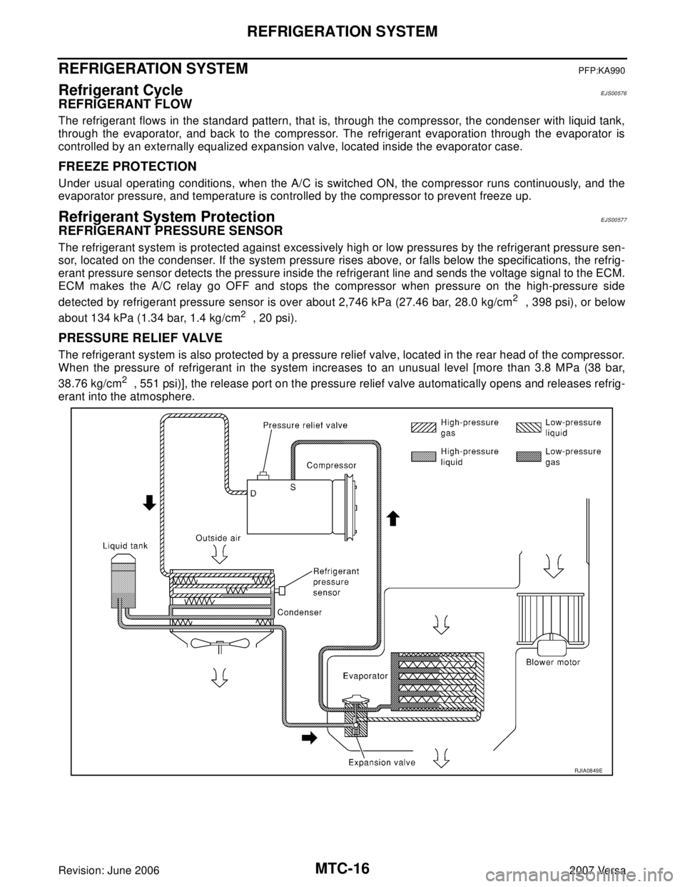
REFRIGERANT FLOW
The refrigerant flows in the standard pattern, that is, through the compressor, the condenser with liquid tank,
through the evaporator, and back to the compressor. The refrigerant evaporation through the evaporator is
controlled by an externally equalized expansion valve, located inside the evaporator case.
FREEZE PROTECTION
Under usual operating conditions, when the A/C is switched ON, the compressor runs continuously, and the
evaporator pressure, and temperature is controlled by the compressor to prevent freeze up.
Refrigerant System ProtectionEJS00577
REFRIGERANT PRESSURE SENSOR
The refrigerant system is protected against excessively high or low pressures by the refrigerant pressure sen-
sor, located on the condenser. If the system pressure rises above, or falls below the specifications, the refrig-
erant pressure sensor detects the pressure inside the refrigerant line and sends the voltage signal to the ECM.
ECM makes the A/C relay go OFF and stops the compressor when pressure on the high-pressure side
detected by refrigerant pressure sensor is over about 2,746 kPa (27.46 bar, 28.0 kg/cm
2 , 398 psi), or below
about 134 kPa (1.34 bar, 1.4 kg/cm
2 , 20 psi).
PRESSURE RELIEF VALVE
The refrigerant system is also protected by a pressure relief valve, located in the rear head of the compressor.
When the pressure of refrigerant in the system increases to an unusual level [more than 3.8 MPa (38 bar,
38.76 kg/cm
2 , 551 psi)], the release port on the pressure relief valve automatically opens and releases refrig-
erant into the atmosphere.
RJIA0849E
Page 2437 of 2896
TROUBLE DIAGNOSIS
MTC-25
C
D
E
F
G
H
I
K
L
MA
B
MTC
Revision: June 20062007 Versa
Component Parts and Harness Connector LocationEJS0057G
ENGINE COMPARTMENT
Insufficient cooling Go to Trouble Diagnosis Procedure for Insufficient Cooling.MTC-50
Insufficient heating Go to Trouble Diagnosis Procedure for Insufficient Heating.MTC-58
Noise Go to Trouble Diagnosis Procedure for Noise.MTC-60
Symptom Reference Page
1. Refrigerant pressure sensor E17 2. A/C compressor F3
WJIA2235E
Page 2456 of 2896
MTC-44
TROUBLE DIAGNOSIS
Revision: June 20062007 Versa
7. CHECK CIRCUIT CONTINUITY BETWEEN FRONT AIR CONTROL AND BCM
1. Turn ignition switch OFF.
2. Disconnect front air control and BCM connector.
3. Check continuity between front air control harness connector
M33 (A) terminal 1and BCM harness connector M18 (B) termi-
nal 27.
OK or NG
OK >> GO TO 8.
NG >> Repair harness or connector.
8. CHECK REFRIGERANT PRESSURE SENSOR
1. Reconnect front air control connector and BCM connector.
2. Check refrigerant pressure sensor. Refer to EC-586, "
REFRIGERANT PRESSURE SENSOR" .
.OK or NG
OK >>�WITH CONSULT-II
GO TO 9.
�WITHOUT CONSULT-II
GO TO 10.
NG >> Replace as necessary.
9. CHECK BCM INPUT (FAN ON) SIGNAL
Check FAN ON/OFF signal. Refer to MTC-24, "
CONSULT-II Func-
tion (BCM)" .
OK or NG
OK >> GO TO 12.
NG >> GO TO 10.1 - 27 :Continuity should exist
SJIA0759E
FAN CONTROL DIAL ON : FAN ON SIG ON
FAN CONTROL DIAL OFF : FAN ON SIG OFF
R J I A 1111E
Page 2471 of 2896
TROUBLE DIAGNOSIS
MTC-59
C
D
E
F
G
H
I
K
L
MA
B
MTC
Revision: June 20062007 Versa
8. CHECK ENGINE COOLANT TEMPERATURE SENSOR
Check engine control temperature sensor. Refer to EC-200, "
DTC P0117, P0118 ECT SENSOR" .
OK or NG
OK >> System OK.
NG >> Repair or replace as necessary. Retest.
9. CHECK HEATER HOSES
Check heater hoses for proper installation.
OK or NG
OK >> GO TO 10.
NG >> Repair /replace as necessary. Retest GO TO 7.
10. BACK FLUSH HEATER CORE
1. Back flush heater core.
2. Drain the water from the system.
3. Refill system with new engine coolant. Refer to CO-8, "
Changing Engine Coolant" .
4. Start engine and warm it up to normal operating temperature.
5. Touch both the inlet and outlet heater hoses.
Is the inlet hose hot and the outlet hose warm? YES or NO
YES >> System OK.
NO >> Replace heater core and refill engine coolant. Refer to MTC-73, "
HEATER CORE" .
Page 2494 of 2896
MTC-82
REFRIGERANT LINES
Revision: June 20062007 Versa
ComponentsEJS0058E
Type 1 A/C System
WJIA2200E
1. Evaporator 2. Expansion valve 3. Low-pressure service valve
4. High-pressure service valve 5. Refrigerant pressure sensor 6. Shaft seal
7. Drain hose
Page 2495 of 2896
REFRIGERANT LINES
MTC-83
C
D
E
F
G
H
I
K
L
MA
B
MTC
Revision: June 20062007 Versa
Type 2 A/C System
WJIA2202E
1. Evaporator 2. Expansion valve 3. Low-pressure service valve
4. High-pressure service valve 5. Refrigerant pressure sensor 6. Shaft seal
7. Drain hose
Page 2500 of 2896

MTC-88
REFRIGERANT LINES
Revision: June 20062007 Versa
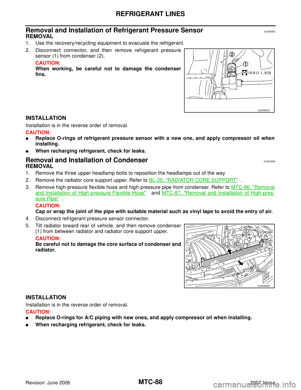
Removal and Installation of Refrigerant Pressure SensorEJS0058J
REMOVAL
1. Use the recovery/recycling equipment to evacuate the refrigerant.
2. Disconnect connector, and then remove refrigerant pressure
sensor (1) from condenser (2).
CAUTION:
When working, be careful not to damage the condenser
fins.
INSTALLATION
Installation is in the reverse order of removal.
CAUTION:
�Replace O-rings of refrigerant pressure sensor with a new one, and apply compressor oil when
installing.
�When recharging refrigerant, check for leaks.
Removal and Installation of CondenserEJS0058K
REMOVAL
1. Remove the three upper headlamp bolts to reposition the headlamps out of the way
2. Remove the radiator core support upper. Refer to BL-20, "
RADIATOR CORE SUPPORT" .
3. Remove high-pressure flexible hose and high-pressure pipe from condenser. Refer to MTC-86, "
Removal
and Installation of High-pressure Flexible Hose" and MTC-87, "Removal and Installation of High-pres-
sure Pipe" .
CAUTION:
Cap or wrap the joint of the pipe with suitable material such as vinyl tape to avoid the entry of air.
4. Disconnect refrigerant pressure sensor connector.
5. Tilt radiator toward rear of vehicle, and then remove condenser
(1) from between radiator and radiator core support upper.
CAUTION:
Be careful not to damage the core surface of condenser and
radiator.
INSTALLATION
Installation is in the reverse order of removal.
CAUTION:
�Replace O-rings for A/C piping with new ones, and apply compressor oil when installing.
�When recharging refrigerant, check for leaks.
SJIA0681E
SJIA0682E
Page 2504 of 2896

MTC-92
REFRIGERANT LINES
Revision: June 20062007 Versa
Checking for Refrigerant LeaksEJS0058O
Perform a visual inspection of all refrigeration parts, fittings, hoses and components for signs of A/C oil leak-
age, damage and corrosion. A/C oil leakage may indicate an area of refrigerant leakage. Allow extra inspec-
tion time in these areas when using either an electronic refrigerant leak detector or fluorescent dye leak
detector.
If dye is observed, confirm the leak with an electronic refrigerant leak detector. It is possible a prior leak was
repaired and not properly cleaned.
When searching for leaks, do not stop when one leak is found but continue to check for additional leaks at all
system components and connections.
When searching for refrigerant leaks using an electronic leak detector, move the probe along the suspected
leak area at 25 to 50 mm (1 to 2 in) per second and no further than 1/4 inch from the component.
CAUTION:
Moving the electronic leak detector probe slower and closer to the suspected leak area will improve
the chances of finding a leak.
Checking System for Leaks Using the Fluorescent Leak DetectorEJS0058P
1. Check A/C system for leaks using the UV lamp and safety goggles J-42220 in a low sunlight area (area
without windows preferable). Illuminate all components, fittings and lines. The dye will appear as a bright
green/yellow area at the point of leakage. Fluorescent dye observed at the evaporator drain opening indi-
cates an evaporator core assembly (tubes, core or expansion valve) leak.
2. If the suspected area is difficult to see, use an adjustable mirror or wipe the area with a clean shop rag or
cloth, with the UV lamp for dye residue.
3. After the leak is repaired, remove any residual dye using dye cleaner J-43872 to prevent future misdiag-
nosis.
4. Perform a system performance check and verify the leak repair with an approved electronic refrigerant
leak detector.
NOTE:
Other gases in the work area or substances on the A/C components, for example, anti-freeze, windshield
washer fluid, solvents and oils, may falsely trigger the leak detector. Make sure the surfaces to be checked are
clean.
Clean with a dry cloth or blow off with shop air.
Do not allow the sensor tip of the detector to contact with any substance. This can also cause false readings
and may damage the detector.
Dye InjectionEJS0058Q
(This procedure is only necessary when recharging the system or when the compressor has seized and was
replaced.)
1. Check A/C system static (at rest) pressure. Pressure must be at least 345 kPa (3.45 bar, 3.52 kg/cm
2 , 50
psi).
2. Pour one bottle (1/4 ounce / 7.4 cc) of the A/C refrigerant dye into the injector tool J-41459.
3. Connect the injector tool to the A/C low-pressure side service fitting.
4. Start engine and switch A/C ON.
5. When the A/C operating (compressor running), inject one bottle (1/4 ounce / 7.4 cc) of fluorescent dye
through the low-pressure service valve using dye injector tool J-41459 (refer to the manufacture’s operat-
ing instructions).
6. With the engine still running, disconnect the injector tool from the service fitting.
CAUTION:
Be careful the A/C system or replacing a component, pour the dye directly into the open system
connection and proceed with the service procedures.
7. Operate the A/C system for a minimum of 20 minutes to mix the dye with the system oil. Depending on the
leak size, operating conditions and location of the leak, it may take from minutes to days for the dye to
penetrate a leak and become visible.