Page 1823 of 2896
 of drive belt auto-tensioner (1) with
a box wrench securely. Then move the wrench handle in the
direction of")
EM-14Revision: June 2006
DRIVE BELTS
2007 Versa
INSTALLATION
1. Hold the hexagonal part (A) of drive belt auto-tensioner (1) with
a box wrench securely. Then move the wrench handle in the
direction of arrow (loosening direction of tensioner).
CAUTION:
Never place hand in a location where pinching may occur if
the holding tool accidentally comes off.
2. Insert a rod such as short-length screwdriver approximately 6
mm (0.24 in) in diameter into the hole (B) of retaining boss to fix
drive belt auto-tensioner.
3. Install drive belt.
CAUTION:
�Confirm drive belt is completely set to pulleys.
�Check for engine oil, working fluid and engine coolant are not adhered to drive belt and each
pulley groove.
4. Release drive belt auto-tensioner, and apply tension to drive belt.
5. Turn crankshaft pulley clockwise several times to equalize tension between each pulley.
6. Confirm tension of drive belt at indicator (notch on fixed side) is within the possible use range. Refer to
EM-13, "
Checking Drive Belts" .
ComponentsEBS00U73
Removal and Installation of Drive Belt Auto-TensionerEBS00U74
REMOVAL
1. Remove drive belt. Refer to EM-13, "Removal and Installation" .
2. Release the fixed drive belt auto-tensioner pulley.
3. Loosen bolt and remove drive belt auto-tensioner.
PBIC3936E
1. Front cover 2. Drive belt auto–tensioner 3. Idler pulley (models without A/C)
4. Bracket (models without A/C) 5. Shaft (models without A/C)
PBIC4698E
Page 1829 of 2896
EM-20Revision: June 2006
INTAKE MANIFOLD
2007 Versa
3. Tighten intake manifold bolt (A). Then tighten intake manifold
bolt (B).
4. Install electronic throttle control actuator
5. Install water hoses (3), (5) to electronic throttle control actuator
as shown.
6. Installation of the remaining components is in the reverse order of removal.
INSPECTION AFTER INSTALLATION
�Check for leaks of engine coolant. Refer to CO-8, "CHECKING COOLING SYSTEM FOR LEAKS" .
�Start and warm up the engine. Visually check for engine coolant leaks.
1 : Intake manifold
: Engine front
PBIC3939E
1 : Electric throttle control actuator
2: Clamp
4 : Water outlet
A: Paint Mark
B : The clamp shall not interfere with the bulged section.
PBIC4703E
Page 1831 of 2896
EM-22Revision: June 2006
EXHAUST MANIFOLD
2007 Versa
5. Loosen nuts in reverse order as shown and remove exhaust
manifold.
CAUTION:
Cover engine openings to avoid entry of foreign materials.
INSPECTION AFTER REMOVAL
Surface Distortion
�Using straightedge (B) and feeler gauge (A), check the surface
distortion of exhaust manifold mating surface in each exhaust
port and entire part.
�If it exceeds the limit, replace exhaust manifold.
INSTALLATION
1. Install exhaust manifold gasket to cylinder head as shown.
2. Tighten exhaust manifold nuts to specification in two stages in
the numerical order as shown.
: Engine front
PBIC3529J
Limit:
Each exhaust port : 0.3 mm (0.012 in)
Entire part : 0.7 mm (0.028 in)
PBIC3530J
: Engine front
PBIC3943E
: Engine front
PBIC3529J
Page 1840 of 2896
IGNITION COIL, SPARK PLUG AND ROCKER COVER
EM-31
C
D
E
F
G
H
I
J
K
L
MA
EM
Revision: June 20062007 Versa
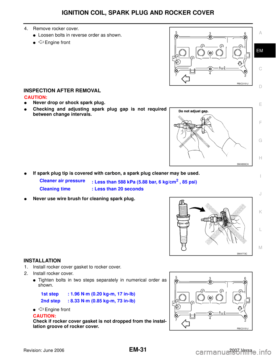
4. Remove rocker cover.
�Loosen bolts in reverse order as shown.
� Engine front
INSPECTION AFTER REMOVAL
CAUTION:
�Never drop or shock spark plug.
�Checking and adjusting spark plug gap is not required
between change intervals.
�If spark plug tip is covered with carbon, a spark plug cleaner may be used.
�Never use wire brush for cleaning spark plug.
INSTALLATION
1. Install rocker cover gasket to rocker cover.
2. Install rocker cover.
�Tighten bolts in two steps separately in numerical order as
shown.
� Engine front
CAUTION:
Check if rocker cover gasket is not dropped from the instal-
lation groove of rocker cover.
PBIC3151J
SM A80 6CA
Cleaner air pressure
: Less than 588 kPa (5.88 bar, 6 kg/cm2 , 85 psi)
Cleaning time : Less than 20 seconds
SM A77 3C
1st step : 1.96 N·m (0.20 kg-m, 17 in-lb)
2nd step : 8.33 N·m (0.85 kg-m, 73 in-lb)
PBIC3151J
Page 1850 of 2896
, and push the slack guide (B) into the inside
of chain tensioner (for oil pump) (1).
�The slack g")
TIMING CHAIN
EM-41
C
D
E
F
G
H
I
J
K
L
MA
EM
Revision: June 20062007 Versa
19. Fully lift up lever (A), and push the slack guide (B) into the inside
of chain tensioner (for oil pump) (1).
�The slack guide is released by fully lifting the lever up. As the
result, the slack guide can be moved.
20. Matching the hole on lever with the hole on tensioner body,
insert a stopper pin (C) to secure slack guide.
NOTE:
Use approximately 1.0 mm (0.04 in) diameter. hard metal pin as
a stopper pin.
21. Remove chain tensioner (for oil pump).
�When the holes on lever and tensioner body cannot be aligned, align these holes by slightly moving the
slack guide.
22. Hold the WAF part of oil pump shaft (A), and then loosen the oil pump sprocket bolt and remove them.
CAUTION:
�Secure the oil pump shaft with the WAF part.
�Never loosen the oil pump sprocket bolt by tightening the
oil pump drive chain.
23. Remove crankshaft sprocket, oil pump sprocket and oil pump drive chain as a set.
24. Remove timing chain tension guide (front cover side) from front cover if necessary.
INSPECTION AFTER REMOVAL
Timing Chain
�Check timing chain and oil pump drive chain for cracks (A) and
any excessive wear (B) at the roller links of timing chain.
�Replace timing chain and/or oil pump drive chain if necessary.
PBIC3453J
1 : Oil pan (upper)
2 : Oil pump
: Engine front
PBIC3539J
PBIC3169J
Page 1852 of 2896
, and then tighten the oil
pump sprocket bolt.
CAUTION:
�Secure the oil pump shaft")
TIMING CHAIN
EM-43
C
D
E
F
G
H
I
J
K
L
MA
EM
Revision: June 20062007 Versa
4. Hold the WAF part of oil pump shaft (A), and then tighten the oil
pump sprocket bolt.
CAUTION:
�Secure the oil pump shaft with the WAF part.
�Never loosen the oil pump sprocket bolt by tightening the
oil pump drive chain.
5. Install chain tensioner (for oil pump) (1).
�Fix the plunger at the most compressed position using a stop-
per pin (A), and then install it.
�Securely pull out ( ) the stopper pin after installing the chain
tensioner (for oil pump).
�Check matching mark position of oil pump drive chain and
each sprocket again.
6. Align the matching marks of each sprocket with the matching
marks of timing chain.
NOTE:
*: There are 2 outer grooves in camshaft sprocket (INT). The
wider one is a matching mark.
�If these matching marks are not aligned, rotate the camshaft
slightly by holding the hexagonal portion to correct the posi-
tion.
CAUTION:
Check matching mark position of each sprocket and timing
chain again after installing the timing chain.
1 : Oil pan (upper)
2 : Oil pump
: Engine front
PBIC3539J
PBIC3456J
1 : Camshaft sprocket (EXH)
2 : Camshaft sprocket (INT)
3 : Timing chain
A : Matching mark (dark blue link)
B : Matching mark (stamping)
C : Matching mark (outer groove*)
D : Matching mark (gold link)
E : Matching mark (stamping)
PBIC3172J
Page 1853 of 2896
 and the timing chain
slack guide (2).
8. Install timing chain tensioner (1).
�Fix the plunger at the most")
EM-44Revision: June 2006
TIMING CHAIN
2007 Versa
7. Install the timing chain tension guide (3) and the timing chain
slack guide (2).
8. Install timing chain tensioner (1).
�Fix the plunger at the most compressed position using a stop-
per pin (A), and then install it.
�Securely pull out the stopper pin after installing the timing
chain tensioner.
9. Check matching mark position of timing chain and each sprocket again.
10. Apply new engine oil to new front oil seal joint surface.
11. Using a suitable tool install front oil seal so that each seal lip is oriented as shown.
�Press-fit front oil seal until it is flush with front end surface of
front cover as shown below with a suitable tool.
CAUTION:
�Be careful not to damage front cover and crankshaft.
�Press-fit oil seal straight to avoid causing burrs or tilting.
�Never touch grease applied onto oil seal lip.
12. Install new O-ring to cylinder block.
1 : Timing chain
PBIC3166J
PBIC3165J
A : Dust seal lip
B: Oil seal lip
: Engine front
: Engine rear
Within 0.3 mm (0.012 in) toward engine front
Within 0.5 mm (0.020 in) toward engine rear
PBIC3485J
Page 1855 of 2896
EM-46Revision: June 2006
TIMING CHAIN
2007 Versa
�If needed use a plastic hammer, tap on its center portion (not circumference) to seat crankshaft
pulley.
18. Secure crankshaft pulley (1) using tool (A).
19. Apply new engine oil to thread and seat surfaces of crankshaft
pulley bolt.
20. Tighten crankshaft pulley bolt in three steps.
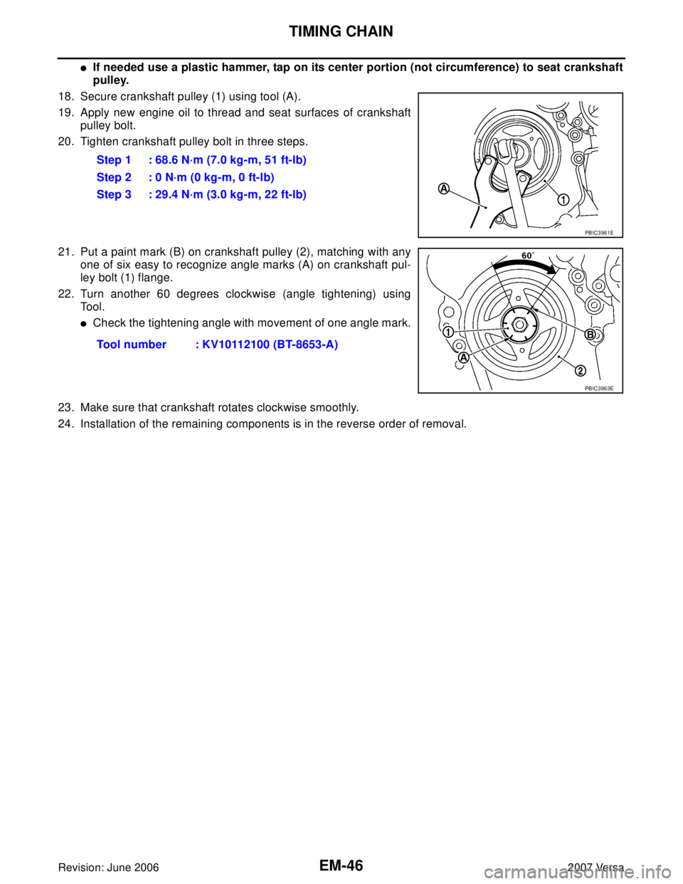
21. Put a paint mark (B) on crankshaft pulley (2), matching with any
one of six easy to recognize angle marks (A) on crankshaft pul-
ley bolt (1) flange.
22. Turn another 60 degrees clockwise (angle tightening) using
Tool.
�Check the tightening angle with movement of one angle mark.
23. Make sure that crankshaft rotates clockwise smoothly.
24. Installation of the remaining components is in the reverse order of removal.Step 1 : 68.6 N·m (7.0 kg-m, 51 ft-lb)
Step 2 : 0 N·m (0 kg-m, 0 ft-lb)
Step 3 : 29.4 N·m (3.0 kg-m, 22 ft-lb)
PBIC3961E
Tool number : KV10112100 (BT-8653-A)
PBIC3963E
. Then tighten intake manifold
bolt (B).
4. Install electronic throttle control actuator
5. Install water hoses (")