2007 NISSAN LATIO door lock
[x] Cancel search: door lockPage 2470 of 2896
MTC-58
TROUBLE DIAGNOSIS
Revision: June 20062007 Versa
Insufficient HeatingEJS0057Q
SYMPTOM: Insufficient heating
INSPECTION FLOW
1. CONFIRM SYMPTOM BY PERFORMING OPERATIONAL CHECK - TEMPERATURE DECREASE
1. Turn temperature control dial clockwise to maximum heat position.
2. Check for hot air at discharge air outlets.
Can the symptom be duplicated?
YES >> GO TO 3.
NO >> GO TO 2.
2. CHECK FOR ANY SYMPTOMS
Perform a complete operational check for any symptoms. Refer to MTC-33, "
Operational Check" .
Does another symptom exist?
YES >> Refer to MTC-24, "SYMPTOM TABLE" .
NO >> System OK.
3. CHECK FOR SERVICE BULLETINS
Check for any service bulletins.
>> GO TO 4.
4. CHECK COOLANT SYSTEM
1. Check engine coolant level. Refer to CO-8, "
ENGINE COOLANT" .
2. Check hoses for leaks or kinks.
3. Check Radiator cap. Refer to CO-13, "
Checking Radiator Cap" .
OK or NG
OK >> GO TO 5.
NG >> Repair/replace as necessary.
5. CHECK AIR MIX DOOR CABLE
Check air mix door cable operation. Refer to MTC-70, "
Air Mix Door Cable Adjustment" .
OK or NG
YES >> GO TO 6.
NO >> Adjust or replace air mix door cable. Refer to MTC-70, "
Air Mix Door Cable Adjustment" .
6. CHECK AIR DUCTS
Check ducts for air leaks.
OK or NG
OK >> GO TO 7.
NG >> Repair air leaks.
7. CHECK HEATER HOSE TEMPERATURES
1. Start engine and warm it up to normal operating temperature.
2. Touch both the inlet and outlet heater hoses.
Is the inlet hose hot and the outlet hose warm? YES or NO
YES >> GO TO 8.
NO >> Both hoses warm: GO TO 9.
Page 2486 of 2896
MTC-74
AIR CONDITIONER FILTER
Revision: June 20062007 Versa
AIR CONDITIONER FILTERPFP:27277
Removal and InstallationEJS0058B
FUNCTION
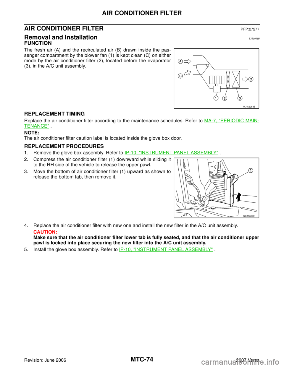
The fresh air (A) and the recirculated air (B) drawn inside the pas-
senger compartment by the blower fan (1) is kept clean (C) on either
mode by the air conditioner filter (2), located before the evaporator
(3), in the A/C unit assembly.
REPLACEMENT TIMING
Replace the air conditioner filter according to the maintenance schedules. Refer to MA-7, "PERIODIC MAIN-
TENANCE" .
NOTE:
The air conditioner filter caution label is located inside the glove box door.
REPLACEMENT PROCEDURES
1. Remove the glove box assembly. Refer to IP-10, "INSTRUMENT PANEL ASSEMBLY" .
2. Compress the air conditioner filter (1) downward while sliding it
to the RH side of the vehicle to release the upper pawl.
3. Move the bottom of air conditioner filter (1) upward as shown to
release the bottom tab, then remove it.
4. Replace the air conditioner filter with new one and install the new filter in the A/C unit assembly.
CAUTION:
Make sure that the air conditioner filter lower tab is fully seated, and that the air conditioner upper
pawl is locked into place securing the new filter into the A/C unit assembly.
5. Install the glove box assembly. Refer to IP-10, "
INSTRUMENT PANEL ASSEMBLY" .
WJIA2253E
SJIA0652E
Page 2517 of 2896

PG-1
POWER SUPPLY, GROUND & CIRCUIT ELEMENTS
K ELECTRICAL
CONTENTS
C
D
E
F
G
H
I
J
L
M
SECTION PG
A
B
PG
Revision: June 20062007 Versa PRECAUTIONS .......................................................... 3
Precautions for Supplemental Restraint System
(SRS) “AIR BAG” and “SEAT BELT PRE-TEN-
SIONER” .................................................................. 3
POWER SUPPLY ROUTING CIRCUIT ...................... 4
Schematic ................................................................ 4
Wiring Diagram — POWER — ................................. 6
BATTERY POWER SUPPLY — IGNITION
SWITCH IN ANY POSITION ................................. 6
ACCESSORY POWER SUPPLY — IGNITION
SWITCH IN ACC AND/OR ON ............................11
IGNITION POWER SUPPLY — IGNITION
SWITCH IN ON ................................................... 12
IGNITION POWER SUPPLY — IGNITION
SWITCH IN ON AND/OR START. ....................... 13
IGNITION POWER SUPPLY — IGNITION
SWITCH IN START ............................................. 15
Fuse ....................................................................... 16
Fusible Link ............................................................ 16
Circuit Breaker (Built Into BCM) ............................. 16
Circuit Breaker ....................................................... 16
IPDM E/R (INTELLIGENT POWER DISTRIBUTION
MODULE ENGINE ROOM) ...................................... 17
System Description ................................................ 17
SYSTEMS CONTROLLED BY IPDM E/R ........... 17
CAN COMMUNICATION LINE CONTROL ......... 17
IPDM E/R STATUS CONTROL ........................... 18
CAN Communication System Description .............. 18
Function of Detecting Ignition Relay Malfunction ... 18
CONSULT-II Function (IPDM E/R) ......................... 19
CONSULT-II START PROCEDURE .................... 19
SELF-DIAGNOSTIC RESULTS .......................... 19
DATA MONITOR ................................................. 20
CAN DIAG SUPPORT MNTR ............................. 20
ACTIVE TEST ..................................................... 20
Auto Active Test ..................................................... 21
DESCRIPTION .................................................... 21
OPERATION PROCEDURE ............................... 21
INSPECTION IN AUTO ACTIVE TEST MODE ... 22
IPDM E/R Terminal Arrangement ........................... 24Terminals and Reference Values for IPDM E/R ...... 25
IPDM E/R Power/Ground Circuit Inspection ........... 28
Inspection with CONSULT-II (Self-Diagnosis) ........ 29
Removal and Installation of IPDM E/R ................... 29
REMOVAL ........................................................... 29
INSTALLATION ................................................... 29
GROUND CIRCUIT ................................................... 30
Ground Distribution ................................................. 30
MAIN HARNESS ................................................. 30
ENGINE ROOM HARNESS ................................ 33
ENGINE CONTROL HARNESS .......................... 35
BODY HARNESS ................................................ 36
BODY NO. 2 HARNESS ..................................... 37
BACK DOOR HARNESS .................................... 38
HARNESS ................................................................. 39
Harness Layout ...................................................... 39
HOW TO READ HARNESS LAYOUT ................. 39
OUTLINE ............................................................. 40
MAIN HARNESS ................................................. 41
ENGINE ROOM HARNESS (LH VIEW) .............. 43
ENGINE ROOM HARNESS (RH VIEW) ............. 45
ENGINE CONTROL HARNESS .......................... 47
BODY HARNESS ................................................ 49
BODY NO. 2 HARNESS ..................................... 51
ROOM LAMP HARNESS .................................... 53
FRONT DOOR LH HARNESS ............................ 55
FRONT DOOR RH HARNESS ............................ 56
REAR DOOR LH HARNESS ............................... 57
REAR DOOR RH HARNESS .............................. 58
BACK DOOR HARNESS .................................... 59
Wiring Diagram Codes (Cell Codes) ...................... 61
ELECTRICAL UNITS LOCATION ............................ 64
Electrical Units Location ......................................... 64
ENGINE COMPARTMENT .................................. 64
PASSENGER COMPARTMENT ......................... 65
LUGGAGE COMPARTMENT .............................. 67
HARNESS CONNECTOR ......................................... 68
Description .............................................................. 68
HARNESS CONNECTOR (TAB-LOCKING
Page 2542 of 2896

PG-26
IPDM E/R (INTELLIGENT POWER DISTRIBUTION MODULE ENGINE ROOM)
Revision: June 20062007 Versa
26 OTail lamp relay (park-
ing lamps)Output — Lighting switch in 2nd position Battery voltage
27 BRTail lamp relay (park-
ing lamps)Output — Lighting switch in 2nd position Battery voltage
28 GRTail lamp relay (park-
ing lamps)Output — Lighting switch in 2nd position Battery voltage
29 PTail lamp relay (park-
ing lamps)Output — Lighting switch in 2nd position Battery voltage
30 R Fuse 54 Output —Ignition switch ON or START Battery voltage
Ignition switch OFF or ACC 0V
31 LG Fuse 55 Output —Ignition switch ON or START Battery voltage
Ignition switch OFF or ACC 0V
32 LWiper high speed sig-
nalOutputON or
STARTWiper switchOFF, LO, INT 0V
HI Battery voltage
33 YWiper low speed sig-
nalOutputON or
STARTWiper switchOFF 0V
LO or INT Battery voltage
35 BRStarter relay (inhibit
switch)InputON or
STARTSelector lever in "P" or "N"
(CVT or A/T) or clutch pedal
depressed (M/T)Battery voltage
Selector lever any other posi-
tion (CVT or A/T) or clutch
pedal released (M/T)0V
36 BR Fuel pump relay Output —Ignition switch ON or START Battery voltage
Ignition switch OFF or ACC 0V
37 G Oil pressure switch InputON or
STARTEngine running and oil pres-
sure within specificationBattery voltage
Engine not running or oil
pressure below specification0V
38 R Wiper auto stop signal InputON or
STARTWipers not in park position Battery voltage
Wipers in park position 0V
39 B Ground Input — — 0V
40 P CAN-L — ON — —
41 L CAN-H — ON — —
45 R Horn relay control Input —Horn switch PUSHED, alarm
switch activated or door lock/
unlock is confirmed when
operating lock system via the
keyfob0V
Horn switch released, alarm
not active, keyfob not activeBattery voltage
46 YThrottle control motor
relay controlInput —Ignition switch ON or START 0V
Ignition switch OFF or ACC Battery voltage
47 GRFuel pump relay con-
trolInput —Ignition switch ON or START 0V
Ignition switch OFF or ACC Battery voltage Te r m i n a lWire
colorSignal nameSignal
input/
outputMeasuring condition
Reference value
(Approx.) Ignition
switchOperation or condition
Page 2558 of 2896

PG-42
HARNESS
Revision: June 20062007 Versa
G1 M1 W/16 : To R1 G1 M47 BR/2 : Front tweeter RH
B3 M2 B/5 : Passenger select unlock relay B2 M48 L/4 : Heated mirror relay
B2 M3 W/1 : Fuse block (J/B) E2 M52 W/40 : Intelligent key unit
B3 M4 W/1 : Fuse block (J/B) B2 M53 W/16 : EPS control unit
B3 M5 W/3 : Illumination control switch B3 M54 B/2 : EPS control unit
C2 M6 W/4 : Steering lock solenoid C3 M55 W/4 : Hazard switch
B3 M7 W/16 : Door mirror remote control switch B2 M57 — : Body ground
A3 M8 W/16 : To D2 F2 M59 W/2 : Glove box lamp
A3 M9 W/16 : To D1 C1 M60 L/2 : EPS control unit
E2 M10 GR/2 : Instrument panel antenna F1 M61 — : Body ground
G3 M11 W/4 : To B106 E2 M62 W/2 : Front blower motor
G4 M12 W/16 : To B101 C1 M63 W/4 : Torque sensor
G3 M13 W/24 : To B102 A2 M69 SMJ : To E7
G3 M14 W/24 : To B120 G3 M74 W/12 : To D102
B4 M15 W/16 : To B23 G3 M75 W/12 : To D101
B4 M16 W/24 : To B24 F2 M77 Y/4 : Front passenger air bag module
D5 M17 B/1 : Parking brake switch A2 M78 B/2 : To E11
F2 M18 W/40 : BCM (body control module) B1 M79 — : Body ground
F2 M19 W/15 : BCM (body control module) D3 M150 W/4 : To M32
F3 M20 B/15 : BCM (body control module) C3 M151 W/4 : Front blower motor resistor
C2 M21 W/4 : NATS antenna amp.
B3 M22 W/16 : Data link connector
E3 M23 W/4 : Remote keyless entry receiver
C1 M24 W/40 : Combination meter
C3 M25 /2 : Diode-1
B2 M26 W/6 : Ignition switch
C2 M27 GR/6 : Key switch and key lock solenoid
C2 M28 W/16 : Combination switch
C3 M29 Y/6 : Combination switch (spiral cable)
C3 M30 GR/8 : Combination switch (spiral cable)
E3 M32 W/4 : To M150
D2 M33 B/15 : Front air control
D4 M35 Y/28 : Air bag diagnosis sensor unit
D2 M36 W/3 : Front passenger air bag OFF indicator
D4 M38 W/6 : A/T device
D4 M38 W/6 : CVT device (without intelligent key)
D4 M38 W/8 : CVT device (with intelligent key)
B3 M39 W/2 : Tire pressure warning check connector
D2 M41 W/2 : Defrost A/C switch
D3 M42 W/3 : Thermo control amp.
D2 M43 W/20 : Audio unit
D2 M44 W/16 : Audio unit
D2 M45 W/12 : Audio unit
A1 M46 BR/2 : Front tweeter LH
Page 2571 of 2896
HARNESS
PG-55
C
D
E
F
G
H
I
J
L
MA
B
PG
Revision: June 20062007 Versa
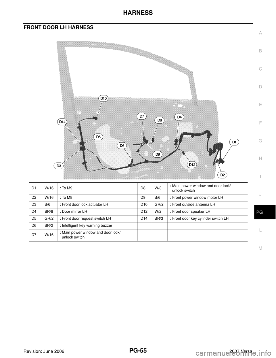
FRONT DOOR LH HARNESS
D1 W/16 : To M9 D8 W/3: Main power window and door lock/
unlock switch
D2 W/16 : To M8 D9 B/6 : Front power window motor LH
D3 B/6 : Front door lock actuator LH D10 GR/2 : Front outside antenna LH
D4 BR/8 : Door mirror LH D12 W/2 : Front door speaker LH
D5 GR/2 : Front door request switch LH D14 BR/3 : Front door key cylinder switch LH
D6 BR/2 : Intelligent key warning buzzer
D7 W/16: Main power window and door lock/
unlock switch
Page 2572 of 2896
PG-56
HARNESS
Revision: June 20062007 Versa
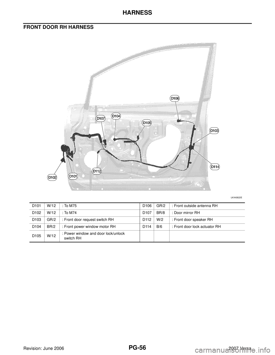
FRONT DOOR RH HARNESS
LKIA0822E
D101 W/12 : To M75 D106 GR/2 : Front outside antenna RH
D102 W/12 : To M74 D107 BR/8 : Door mirror RH
D103 GR/2 : Front door request switch RH D112 W/2 : Front door speaker RH
D104 BR/2 : Front power window motor RH D114 B/6 : Front door lock actuator RH
D105 W/12: Power window and door lock/unlock
switch RH
Page 2573 of 2896
HARNESS
PG-57
C
D
E
F
G
H
I
J
L
MA
B
PG
Revision: June 20062007 Versa
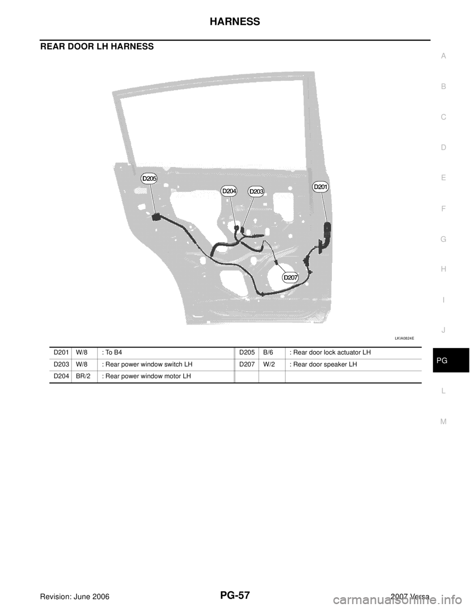
REAR DOOR LH HARNESS
LKIA0824E
D201 W/8 : To B4 D205 B/6 : Rear door lock actuator LH
D203 W/8 : Rear power window switch LH D207 W/2 : Rear door speaker LH
D204 BR/2 : Rear power window motor LH