Page 1909 of 2896

EM-100Revision: June 2006
CYLINDER BLOCK
2007 Versa
�If it exceeds the limit, replace piston and piston pin assembly and/or cylinder block. Refer to EM-87,
"HOW TO SELECT PISTON" .
CRANKSHAFT MAIN JOURNAL DIAMETER
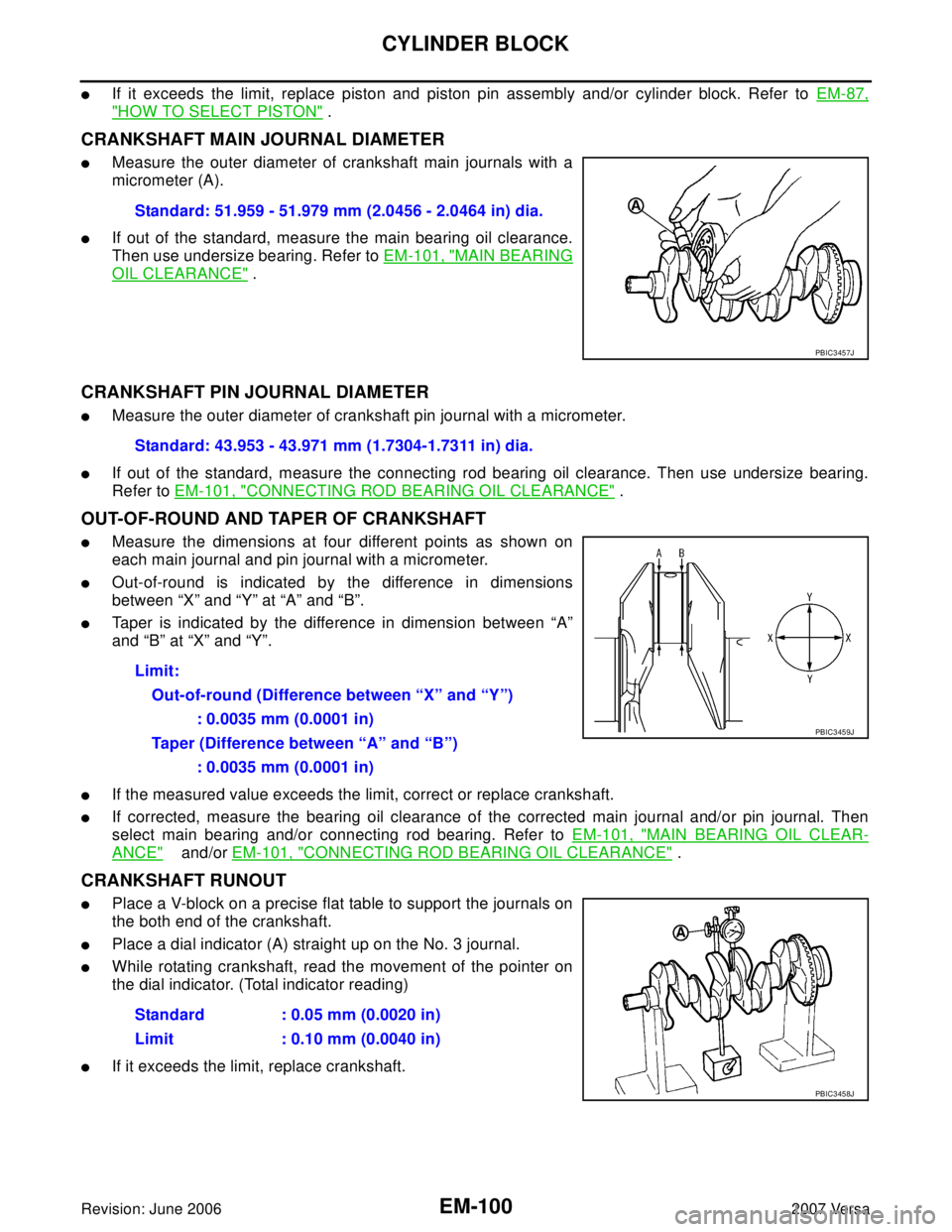
�Measure the outer diameter of crankshaft main journals with a
micrometer (A).
�If out of the standard, measure the main bearing oil clearance.
Then use undersize bearing. Refer to EM-101, "
MAIN BEARING
OIL CLEARANCE" .
CRANKSHAFT PIN JOURNAL DIAMETER
�Measure the outer diameter of crankshaft pin journal with a micrometer.
�If out of the standard, measure the connecting rod bearing oil clearance. Then use undersize bearing.
Refer to EM-101, "
CONNECTING ROD BEARING OIL CLEARANCE" .
OUT-OF-ROUND AND TAPER OF CRANKSHAFT
�Measure the dimensions at four different points as shown on
each main journal and pin journal with a micrometer.
�Out-of-round is indicated by the difference in dimensions
between “X” and “Y” at “A” and “B”.
�Taper is indicated by the difference in dimension between “A”
and “B” at “X” and “Y”.
�If the measured value exceeds the limit, correct or replace crankshaft.
�If corrected, measure the bearing oil clearance of the corrected main journal and/or pin journal. Then
select main bearing and/or connecting rod bearing. Refer to EM-101, "
MAIN BEARING OIL CLEAR-
ANCE" and/or EM-101, "CONNECTING ROD BEARING OIL CLEARANCE" .
CRANKSHAFT RUNOUT
�Place a V-block on a precise flat table to support the journals on
the both end of the crankshaft.
�Place a dial indicator (A) straight up on the No. 3 journal.
�While rotating crankshaft, read the movement of the pointer on
the dial indicator. (Total indicator reading)
�If it exceeds the limit, replace crankshaft.Standard: 51.959 - 51.979 mm (2.0456 - 2.0464 in) dia.
PBIC3457J
Standard: 43.953 - 43.971 mm (1.7304-1.7311 in) dia.
Limit:
Out-of-round (Difference between “X” and “Y”)
: 0.0035 mm (0.0001 in)
Taper (Difference between “A” and “B”)
: 0.0035 mm (0.0001 in)
PBIC3459J
Standard : 0.05 mm (0.0020 in)
Limit : 0.10 mm (0.0040 in)
PBIC3458J
Page 2657 of 2896

SHOCK ABSORBER
RSU-9
C
D
F
G
H
I
J
K
L
MA
B
RSU
Revision: June 20062007 Versa
SHOCK ABSORBERPFP:56210
Removal and InstallationEES002D0
REMOVAL
1. Remove rear tires from vehicle using power tool.
2. Remove wheel sensor from wheel hub and bearing assembly and rear suspension beam. Refer to BRC-
33, "WHEEL SENSORS" .
CAUTION:
Do not pull on wheel sensor harness.
3. Remove shock absorber mask from trunk side finisher using a flat-bladed screwdriver. Refer to EI-42,
"LUGGAGE FLOOR TRIM" .
CAUTION:
Wrap the tip of a screwdriver with cloth to avoid damaging components.
4. Set jack under rear suspension beam.
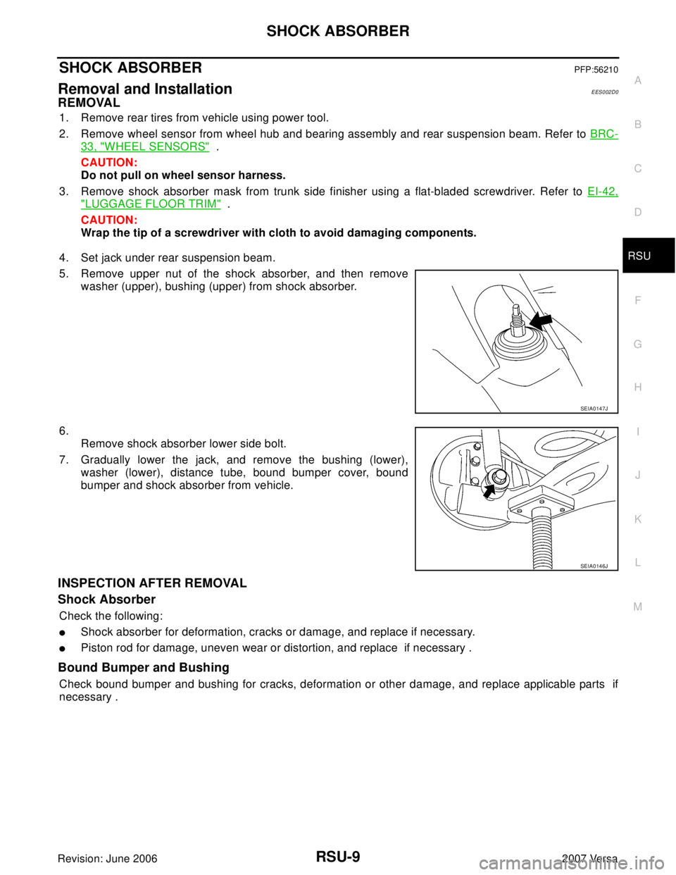
5. Remove upper nut of the shock absorber, and then remove
washer (upper), bushing (upper) from shock absorber.
6.
Remove shock absorber lower side bolt.
7. Gradually lower the jack, and remove the bushing (lower),
washer (lower), distance tube, bound bumper cover, bound
bumper and shock absorber from vehicle.
INSPECTION AFTER REMOVAL
Shock Absorber
Check the following:
�Shock absorber for deformation, cracks or damage, and replace if necessary.
�Piston rod for damage, uneven wear or distortion, and replace if necessary .
Bound Bumper and Bushing
Check bound bumper and bushing for cracks, deformation or other damage, and replace applicable parts if
necessary .
SEIA0147J
SEIA0146J
Page 2823 of 2896

ROAD WHEEL
WT-5
C
D
F
G
H
I
J
K
L
MA
B
WT
Revision: June 20062007 Versa
ROAD WHEELPFP:40300
InspectionEES002D7
ALUMINUM WHEEL
1. Check tires for wear and improper inflation.
2. Check wheels for deformation, cracks and other damage. If deformed, remove wheel and check wheel
runout.
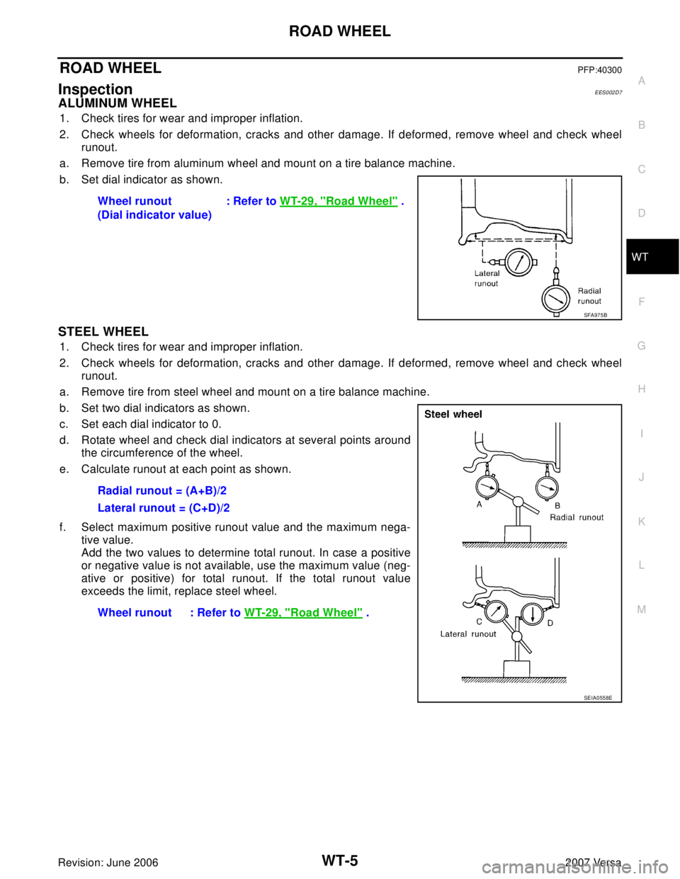
a. Remove tire from aluminum wheel and mount on a tire balance machine.
b. Set dial indicator as shown.
STEEL WHEEL
1. Check tires for wear and improper inflation.
2. Check wheels for deformation, cracks and other damage. If deformed, remove wheel and check wheel
runout.
a. Remove tire from steel wheel and mount on a tire balance machine.
b. Set two dial indicators as shown.
c. Set each dial indicator to 0.
d. Rotate wheel and check dial indicators at several points around
the circumference of the wheel.
e. Calculate runout at each point as shown.
f. Select maximum positive runout value and the maximum nega-
tive value.
Add the two values to determine total runout. In case a positive
or negative value is not available, use the maximum value (neg-
ative or positive) for total runout. If the total runout value
exceeds the limit, replace steel wheel.Wheel runout
(Dial indicator value): Refer to WT-29, "
Road Wheel" .
SFA975B
Radial runout = (A+B)/2
Lateral runout = (C+D)/2
Wheel runout : Refer to WT-29, "
Road Wheel" .
SEIA0558E