Page 90 of 2896
TROUBLE DIAGNOSIS
AT-77
D
E
F
G
H
I
J
K
L
MA
B
AT
Revision: June 20062007 Versa
OthersATF shoots out during
operation.
White smoke emitted
from exhaust pipe
during operation.ON vehicle 1. A/T fluid levelAT- 1 6
OFF vehicle2. Reverse clutchAT- 3 0 9
3. High clutchAT- 3 1 4
4. Brake bandAT- 3 4 3
5. Forward clutchAT- 3 2 0
6. Overrun clutchAT- 3 2 0
7. Low & reverse brakeAT- 3 2 7
Unusual smell at A/T
fluid charging pipe.ON vehicle 1. A/T fluid levelAT- 1 6
OFF vehicle2. Torque converterAT- 2 6 8
3. Oil pumpAT- 2 8 9
4. Reverse clutchAT- 3 0 9
5. High clutchAT- 3 1 4
6. Brake bandAT- 3 4 3
7. Forward clutchAT- 3 2 0
8. Overrun clutchAT- 3 2 0
9. Low & reverse brakeAT- 3 2 7
Items Symptom Condition Diagnostic item Reference page
Page 214 of 2896

TROUBLE DIAGNOSIS FOR SYMPTOMS
AT-201
D
E
F
G
H
I
J
K
L
MA
B
AT
Revision: June 20062007 Versa
In “P” Position, Vehicle Moves Forward or Backward When PushedUCS005UY
SYMPTOM:
Vehicle moves when it is pushed forward or backward with selector lever in “P” position.
DIAGNOSTIC PROCEDURE
1. CHECK A/T POSITION
Check A/T position. Refer to AT-234, "
Checking of A/T Position" .
OK or NG
OK >> GO TO 2.
NG >> Adjust A/T position. Refer to AT-233, "
Adjustment of A/T Position" .
2. CHECK PARKING COMPONENTS
Check parking components. Refer to AT-257, "
Components" and
AT- 2 6 8 , "
DISASSEMBLY" .
OK or NG
OK >>INSPECTION END
NG >> Repair or replace damaged parts.
In “N” Position, Vehicle MovesUCS005UZ
SYMPTOM:
Vehicle moves forward or backward when selecting “N” position.
DIAGNOSTIC PROCEDURE
1. CHECK A/T POSITION
Check A/T position. Refer to AT-234, "
Checking of A/T Position" .
OK or NG
OK >> GO TO 2.
NG >> Adjust A/T position. Refer to AT-233, "
Adjustment of A/T Position" .
2. CHECK A/T FLUID LEVEL
Check A/T fluid level. Refer to AT- 1 6 , "
Checking A/T Fluid" .
OK or NG
OK >> GO TO 3.
NG >> Refill ATF.
3. CHECK A/T FLUID CONDITION
1. Remove oil pan. Refer to AT-257, "
Components" .
2. Check A/T fluid condition. Refer to AT-53, "
Fluid Condition Check" .
OK or NG
OK >> GO TO 5.
NG >> GO TO 4.
SAT2 8 2F
Page 216 of 2896

TROUBLE DIAGNOSIS FOR SYMPTOMS
AT-203
D
E
F
G
H
I
J
K
L
MA
B
AT
Revision: June 20062007 Versa
3. DETECT MALFUNCTIONING ITEM
1. Remove control valve assembly. Refer to AT-242, "
Control Valve Assembly and Accumulators" .
2. Check the following items:
–Valves to control line pressure (Pressure regulator valve, pressure modifier valve, pilot valve and pilot fil-
ter)
–Line pressure solenoid valve
–Oil pump assembly. Refer to AT-289, "Oil Pump" .
OK or NG
OK >> GO TO 4.
NG >> Repair or replace damaged parts.
4. CHECK SYMPTOM
Check again. Refer to AT- 5 9 , "
Check at Idle" .
OK or NG
OK >>INSPECTION END
NG >> GO TO 5.
5. CHECK TCM
1. Check TCM input/output signals. Refer to AT- 7 8 , "
TCM Terminals and Reference Value" .
2. If NG, recheck TCM pin terminals for damage or loose connection with harness connector.
OK or NG
OK >>INSPECTION END
NG >> Repair or replace damaged parts.
Vehicle Does Not Creep Backward in “R” PositionUCS005V1
SYMPTOM:
Vehicle does not creep backward when selecting “R” position.
DIAGNOSTIC PROCEDURE
1. CHECK A/T FLUID LEVEL
Check A/T fluid level. Refer to AT- 1 6 , "
Checking A/T Fluid" .
OK or NG
OK >> GO TO 2.
NG >> Refill ATF.
2. CHECK LINE PRESSURE
Check line pressure at idle with selector lever in “R” position. Refer to AT-56, "
LINE PRESSURE TEST" .
OK or NG
OK >> GO TO 4.
NG >> GO TO 3.
Page 218 of 2896

TROUBLE DIAGNOSIS FOR SYMPTOMS
AT-205
D
E
F
G
H
I
J
K
L
MA
B
AT
Revision: June 20062007 Versa
8. CHECK SYMPTOM
Check again. Refer to AT- 5 9 , "
Check at Idle" .
OK or NG
OK >>INSPECTION END
NG >> GO TO 9.
9. CHECK TCM
1. Check TCM input/output signals. Refer to AT- 7 8 , "
TCM Terminals and Reference Value" .
2. If NG, recheck TCM pin terminals for damage or loose connection with harness connector.
OK or NG
OK >>INSPECTION END
NG >> Repair or replace damaged parts.
Vehicle Does Not Creep Forward in “D”, “2” or “1” Position UCS005V2
SYMPTOM:
Vehicle does not creep forward when selecting “D”, “2” or “1” position.
DIAGNOSTIC PROCEDURE
1. CHECK A/T FLUID LEVEL
Check A/T fluid level. Refer to AT- 1 6 , "
Checking A/T Fluid" .
OK or NG
OK >> GO TO 2.
NG >> Refill ATF.
2. CHECK LINE PRESSURE
Check line pressure at idle with selector lever in “D” position. Refer to AT-56, "
LINE PRESSURE TEST" .
OK or NG
OK >> GO TO 4.
NG >> GO TO 3.
3. DETECT MALFUNCTIONING ITEM
1. Remove control valve assembly. Refer to AT-242, "
Control Valve Assembly and Accumulators" .
2. Check the following items:
–Valves to control line pressure (Pressure regulator valve, pressure modifier valve, pilot valve and pilot fil-
ter)
–Line pressure solenoid valve
3. Disassemble A/T. Refer to AT- 2 6 8 , "
Disassembly" .
4. Check the following item:
–Oil pump assembly. Refer to AT-289, "Oil Pump" .
OK or NG
OK >> GO TO 4.
NG >> Repair or replace damaged parts.
4. CHECK STALL REVOLUTION
Check stall revolution with selector lever in “D” position. Refer to AT-53, "
STALL TEST" .
OK or NG
OK >> GO TO 6.
NG >> GO TO 5.
Page 258 of 2896

ON-VEHICLE SERVICE
AT-245
D
E
F
G
H
I
J
K
L
MA
B
AT
Revision: June 20062007 Versa
Inspection
�Inspect the sliding surfaces of each accumulator piston and
transaxle case, and replace if damaged or dented.
(1): Servo release accumulator piston
(2): N-D accumulator piston
�Inspect the sliding surfaces of manual valve and valve body, and
replace if damaged or dented.
�Inspect each return spring, and replace if damaged, deformed or
worn. Refer to AT-380, "
Accumulator" for free length (L1 ) and
length (L
2 ).
(1): Return spring (Servo release accumulator)
(2): Return spring (N-D accumulator)
CAUTION:
Do not remove spring retainer (3).
Installation
Installation is in the reverse order of removal.
CAUTION:
�Completely remove all moisture, oil and old gasket from the oil pan gasket mounting surface of
transaxle case and oil pan.
�Do not reuse O-rings, lip seals, oil pan gasket and oil pan bolts.
�Apply ATF to manual valve, O-rings, lip seals and sliding surfaces of the transaxle case.
NOTE:
�Set manual shaft in “N” position, then align manual plate (1) with
groove in manual valve (2).
�After installing control valve assembly to transaxle case, make
sure that selector lever can be moved to all positions.
�After completing installation, check for A/T fluid leakage and A/T
fluid level. Refer to AT- 1 6 , "
Checking A/T Fluid" .
WCIA0652E
SCIA6955E
SCIA7090E
Page 264 of 2896
ON-VEHICLE SERVICE
AT-251
D
E
F
G
H
I
J
K
L
MA
B
AT
Revision: June 20062007 Versa
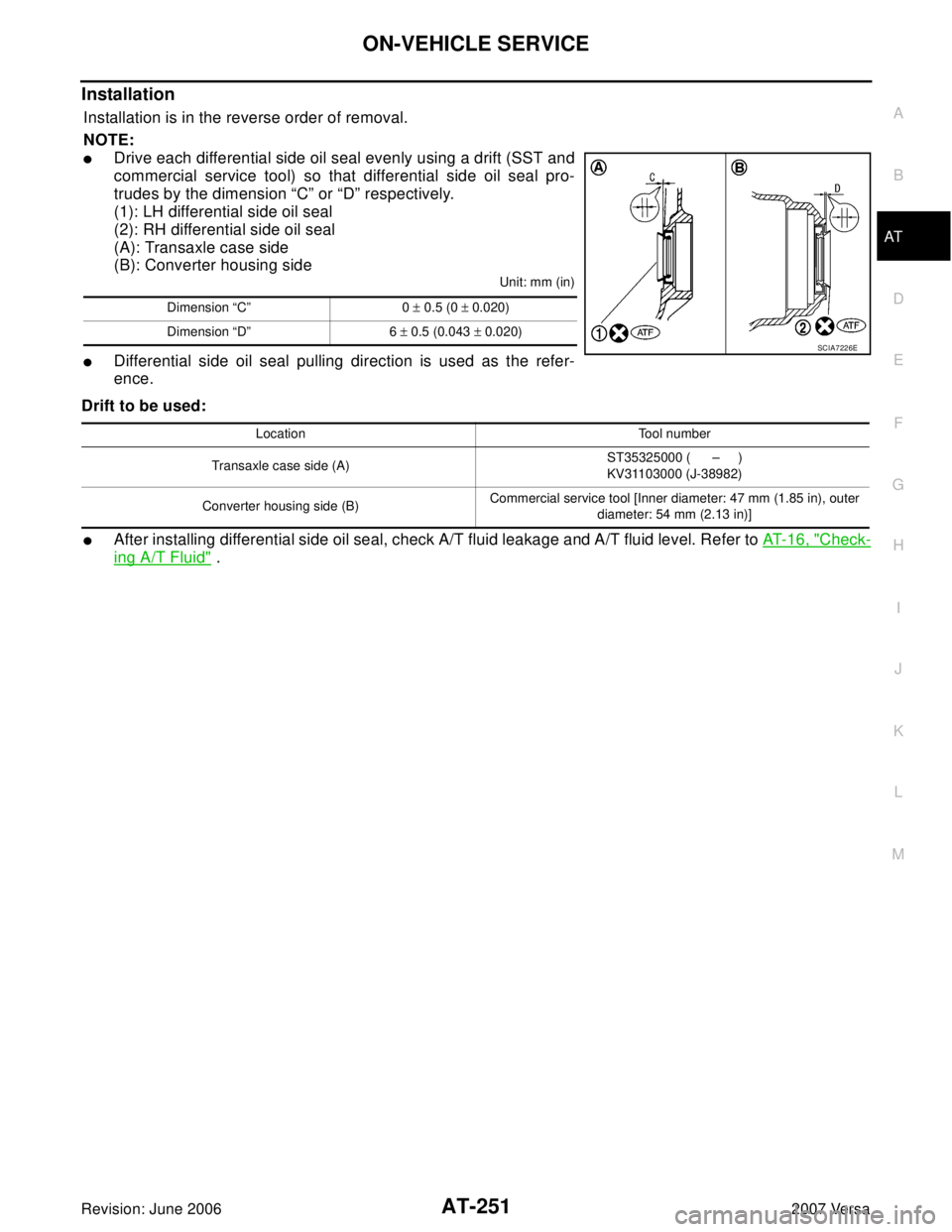
Installation
Installation is in the reverse order of removal.
NOTE:
�Drive each differential side oil seal evenly using a drift (SST and
commercial service tool) so that differential side oil seal pro-
trudes by the dimension “C” or “D” respectively.
(1): LH differential side oil seal
(2): RH differential side oil seal
(A): Transaxle case side
(B): Converter housing side
Unit: mm (in)
�Differential side oil seal pulling direction is used as the refer-
ence.
Drift to be used:
�After installing differential side oil seal, check A/T fluid leakage and A/T fluid level. Refer to AT- 1 6 , "Check-
ing A/T Fluid" .
Dimension “C” 0 ± 0.5 (0 ± 0.020)
Dimension “D” 6 ± 0.5 (0.043 ± 0.020)
SCIA7226E
Location Tool number
Transaxle case side (A)ST35325000 ( – )
KV31103000 (J-38982)
Converter housing side (B)Commercial service tool [Inner diameter: 47 mm (1.85 in), outer
diameter: 54 mm (2.13 in)]
Page 798 of 2896

BRAKE MASTER CYLINDER
BR-15
C
D
E
G
H
I
J
K
L
MA
B
BR
Revision: June 20062007 Versa
Disassembly and AssemblyEFS006JH
COMPONENTS
DISASSEMBLY
CAUTION:
While working, cover primary piston rod with cloth to prevent it from being damaged.
1. Secure flange of cylinder body in vise as shown.
CAUTION:
�Use copper plate or cloth to cover flange when securing
in vise.
�When securing master cylinder assembly in a vise, be
sure not to over-tighten.
2. Using a pin-punch [commercial service tool: diameter approx. 4
mm (0.16 in)], remove pin from reservoir tank.
3. Remove master cylinder assembly from vise.
4. Remove reservoir tank and grommet from cylinder body.
1. Reservoir cap 2. Oil filter 3. Reservoir tank
4. Grommet 5. Piston stopper 6. Cylinder body
7. Pin 8. Brake fluid level switch connector 9. O-ring
10. Secondary piston assembly 11. Primary piston assembly 12. Plate
13. Guide assembly 14. Snap ring
:PBC (Poly Butyl Cuprysil) grease
or silicone-based grease:Brake fluid
Refer to GI section GI-10, "
Components" for symbol marks unless shown.
SFIA3094E
WFIA0514E
WFIA0515E
Page 940 of 2896

TROUBLE DIAGNOSIS
CVT-43
D
E
F
G
H
I
J
K
L
MA
B
CVT
Revision: June 20062007 Versa
Inspections before Trouble DiagnosisUCS005YB
CVT FLUID CHECK
Fluid Leakage and Fluid Level Check
�Inspect for fluid leakage and check the fluid level. Refer to CVT-16, "Checking CVT Fluid" .
Fluid Condition Check
Inspect the fluid condition.
STALL TEST
Stall Test Procedure
1. Inspect the amount of engine oil. Replenish the engine oil if necessary.
2. Drive for about 10 minutes to warm up the vehicle so that the
CVT fluid temperature is 50 to 80°C (122 to 176°F). Inspect the
amount of CVT fluid. Replenish if necessary.
3. Securely engage the parking brake so that the tires do not turn.
4. Install a tachometer where it can be seen by driver during test.
�It is good practice to mark the point of specified engine
rpm on indicator.
5. Start engine, apply foot brake, and place selector lever in “D”
position.
Fluid status Conceivable cause Required operation
Varnished (viscous
varnish state)Clutch, brake
scorchedReplace the CVT fluid and check
the CVT main unit and the vehicle
for malfunctions (wire harnesses,
cooler pipes, etc.)
Milky white or
cloudyWater in the fluidReplace the CVT fluid and check for
places where water is getting in.
Large amount of
metal powder mixed
inUnusual wear of
sliding parts within
CVTReplace the CVT fluid and check for
improper operation of the CVT.
SAT6 3 8A
SAT6 4 7B
SAT5 1 3G
SAT7 7 5B