Page 1340 of 2896
DTC P0037, P0038 HO2S2 HEATER
EC-171
C
D
E
F
G
H
I
J
K
L
MA
EC
Revision: June 20062007 Versa
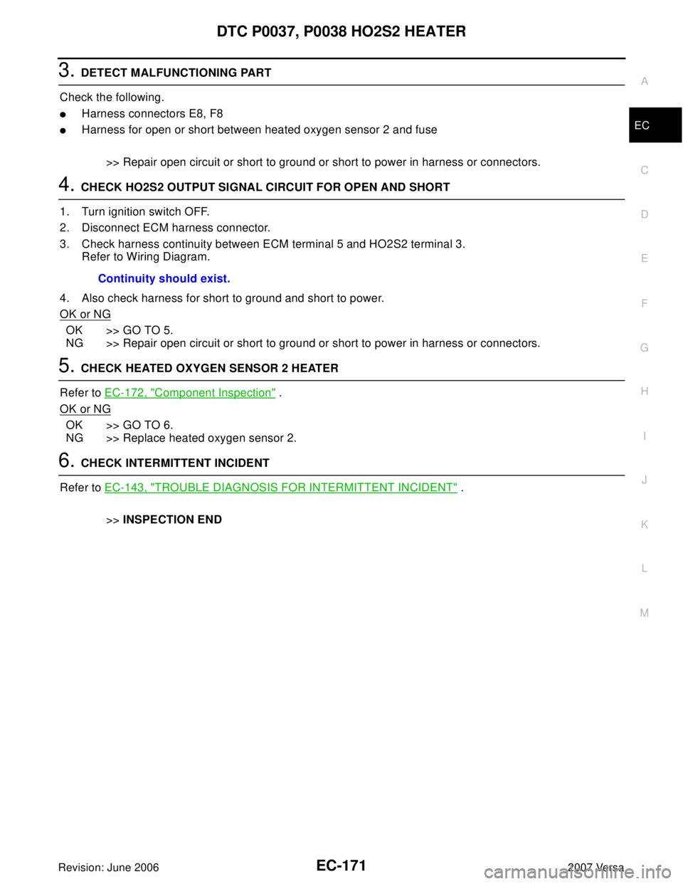
3. DETECT MALFUNCTIONING PART
Check the following.
�Harness connectors E8, F8
�Harness for open or short between heated oxygen sensor 2 and fuse
>> Repair open circuit or short to ground or short to power in harness or connectors.
4. CHECK HO2S2 OUTPUT SIGNAL CIRCUIT FOR OPEN AND SHORT
1. Turn ignition switch OFF.
2. Disconnect ECM harness connector.
3. Check harness continuity between ECM terminal 5 and HO2S2 terminal 3.
Refer to Wiring Diagram.
4. Also check harness for short to ground and short to power.
OK or NG
OK >> GO TO 5.
NG >> Repair open circuit or short to ground or short to power in harness or connectors.
5. CHECK HEATED OXYGEN SENSOR 2 HEATER
Refer to EC-172, "
Component Inspection" .
OK or NG
OK >> GO TO 6.
NG >> Replace heated oxygen sensor 2.
6. CHECK INTERMITTENT INCIDENT
Refer to EC-143, "
TROUBLE DIAGNOSIS FOR INTERMITTENT INCIDENT" .
>>INSPECTION END Continuity should exist.
Page 1394 of 2896
DTC P0130 A/F SENSOR 1
EC-225
C
D
E
F
G
H
I
J
K
L
MA
EC
Revision: June 20062007 Versa
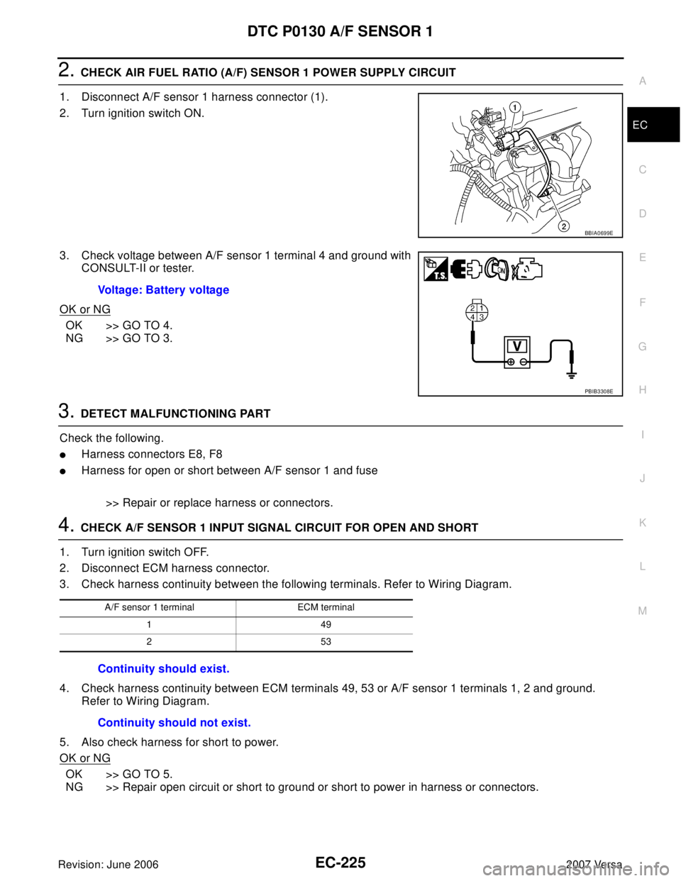
2. CHECK AIR FUEL RATIO (A/F) SENSOR 1 POWER SUPPLY CIRCUIT
1. Disconnect A/F sensor 1 harness connector (1).
2. Turn ignition switch ON.
3. Check voltage between A/F sensor 1 terminal 4 and ground with
CONSULT-II or tester.
OK or NG
OK >> GO TO 4.
NG >> GO TO 3.
3. DETECT MALFUNCTIONING PART
Check the following.
�Harness connectors E8, F8
�Harness for open or short between A/F sensor 1 and fuse
>> Repair or replace harness or connectors.
4. CHECK A/F SENSOR 1 INPUT SIGNAL CIRCUIT FOR OPEN AND SHORT
1. Turn ignition switch OFF.
2. Disconnect ECM harness connector.
3. Check harness continuity between the following terminals. Refer to Wiring Diagram.
4. Check harness continuity between ECM terminals 49, 53 or A/F sensor 1 terminals 1, 2 and ground.
Refer to Wiring Diagram.
5. Also check harness for short to power.
OK or NG
OK >> GO TO 5.
NG >> Repair open circuit or short to ground or short to power in harness or connectors.
BBIA0699E
Voltage: Battery voltage
PBIB3308E
A/F sensor 1 terminal ECM terminal
149
253
Continuity should exist.
Continuity should not exist.
Page 1400 of 2896
DTC P0131 A/F SENSOR 1
EC-231
C
D
E
F
G
H
I
J
K
L
MA
EC
Revision: June 20062007 Versa
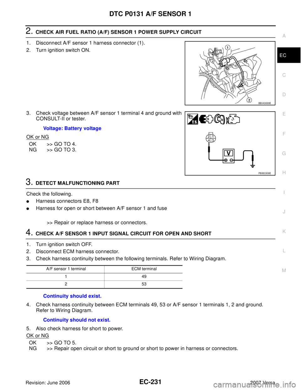
2. CHECK AIR FUEL RATIO (A/F) SENSOR 1 POWER SUPPLY CIRCUIT
1. Disconnect A/F sensor 1 harness connector (1).
2. Turn ignition switch ON.
3. Check voltage between A/F sensor 1 terminal 4 and ground with
CONSULT-II or tester.
OK or NG
OK >> GO TO 4.
NG >> GO TO 3.
3. DETECT MALFUNCTIONING PART
Check the following.
�Harness connectors E8, F8
�Harness for open or short between A/F sensor 1 and fuse
>> Repair or replace harness or connectors.
4. CHECK A/F SENSOR 1 INPUT SIGNAL CIRCUIT FOR OPEN AND SHORT
1. Turn ignition switch OFF.
2. Disconnect ECM harness connector.
3. Check harness continuity between the following terminals. Refer to Wiring Diagram.
4. Check harness continuity between ECM terminals 49, 53 or A/F sensor 1 terminals 1, 2 and ground.
Refer to Wiring Diagram.
5. Also check harness for short to power.
OK or NG
OK >> GO TO 5.
NG >> Repair open circuit or short to ground or short to power in harness or connectors.
BBIA0699E
Voltage: Battery voltage
PBIB3308E
A/F sensor 1 terminal ECM terminal
149
253
Continuity should exist.
Continuity should not exist.
Page 1406 of 2896
DTC P0132 A/F SENSOR 1
EC-237
C
D
E
F
G
H
I
J
K
L
MA
EC
Revision: June 20062007 Versa
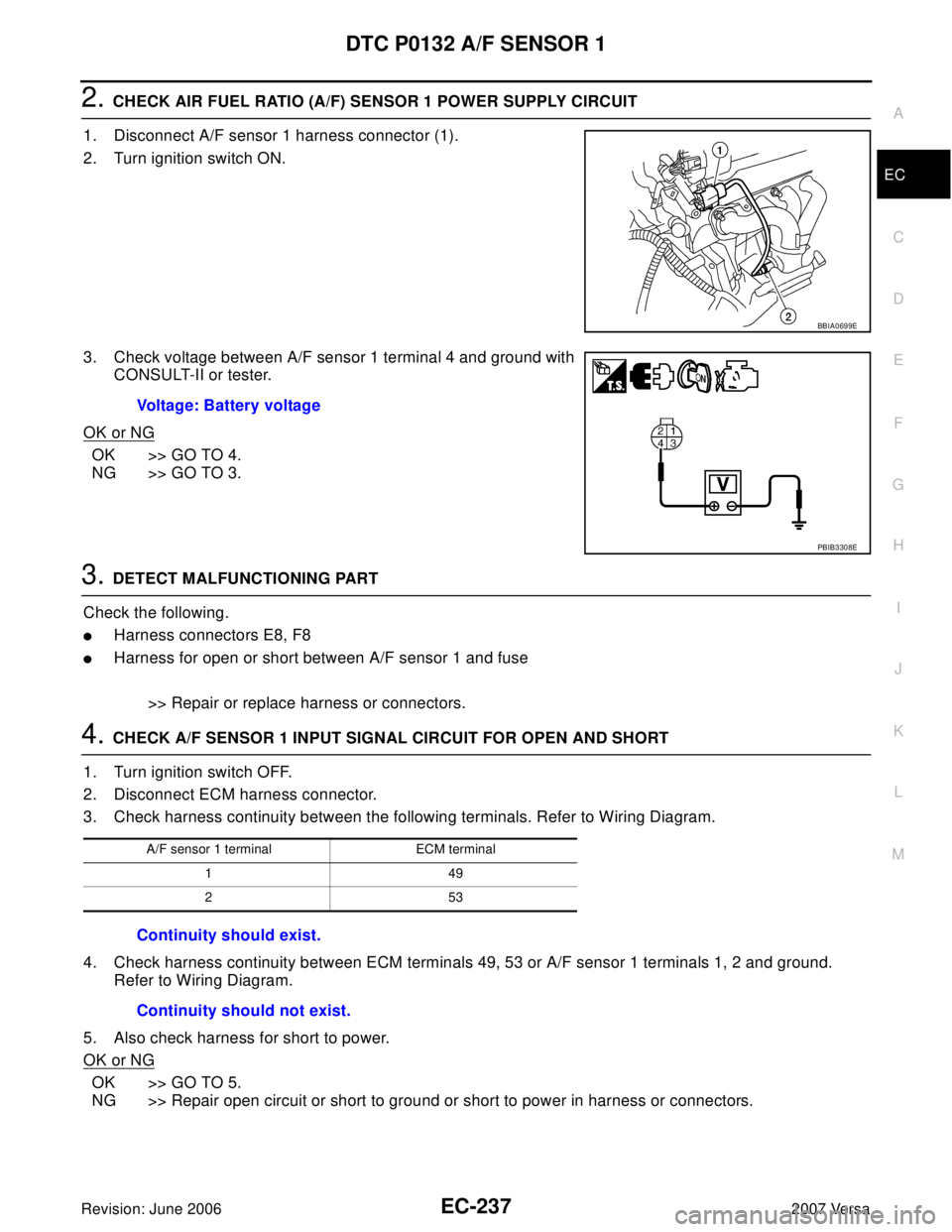
2. CHECK AIR FUEL RATIO (A/F) SENSOR 1 POWER SUPPLY CIRCUIT
1. Disconnect A/F sensor 1 harness connector (1).
2. Turn ignition switch ON.
3. Check voltage between A/F sensor 1 terminal 4 and ground with
CONSULT-II or tester.
OK or NG
OK >> GO TO 4.
NG >> GO TO 3.
3. DETECT MALFUNCTIONING PART
Check the following.
�Harness connectors E8, F8
�Harness for open or short between A/F sensor 1 and fuse
>> Repair or replace harness or connectors.
4. CHECK A/F SENSOR 1 INPUT SIGNAL CIRCUIT FOR OPEN AND SHORT
1. Turn ignition switch OFF.
2. Disconnect ECM harness connector.
3. Check harness continuity between the following terminals. Refer to Wiring Diagram.
4. Check harness continuity between ECM terminals 49, 53 or A/F sensor 1 terminals 1, 2 and ground.
Refer to Wiring Diagram.
5. Also check harness for short to power.
OK or NG
OK >> GO TO 5.
NG >> Repair open circuit or short to ground or short to power in harness or connectors.
BBIA0699E
Voltage: Battery voltage
PBIB3308E
A/F sensor 1 terminal ECM terminal
149
253
Continuity should exist.
Continuity should not exist.
Page 1415 of 2896
EC-246Revision: June 2006
DTC P0133 A/F SENSOR 1
2007 Versa
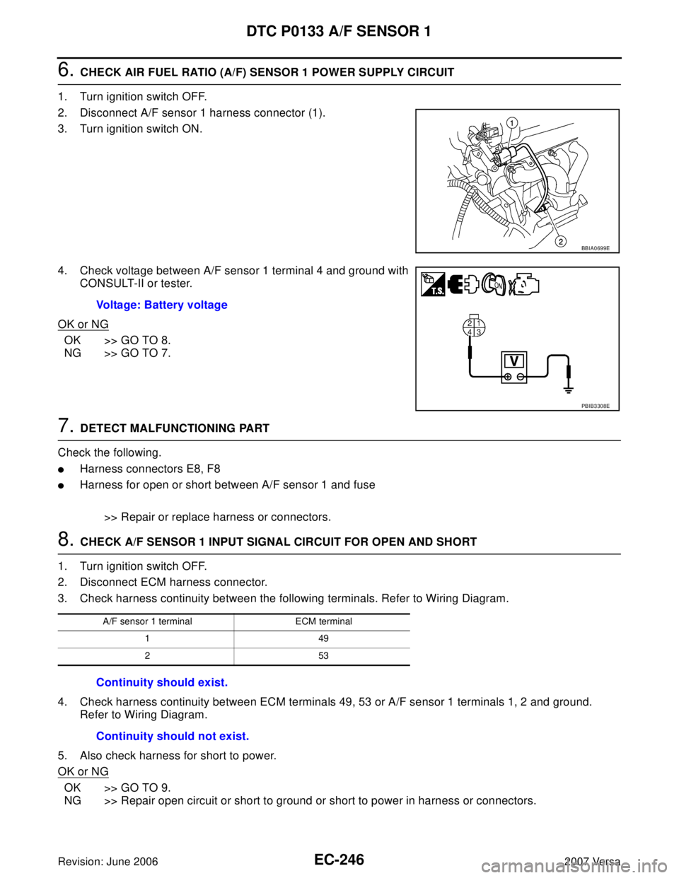
6. CHECK AIR FUEL RATIO (A/F) SENSOR 1 POWER SUPPLY CIRCUIT
1. Turn ignition switch OFF.
2. Disconnect A/F sensor 1 harness connector (1).
3. Turn ignition switch ON.
4. Check voltage between A/F sensor 1 terminal 4 and ground with
CONSULT-II or tester.
OK or NG
OK >> GO TO 8.
NG >> GO TO 7.
7. DETECT MALFUNCTIONING PART
Check the following.
�Harness connectors E8, F8
�Harness for open or short between A/F sensor 1 and fuse
>> Repair or replace harness or connectors.
8. CHECK A/F SENSOR 1 INPUT SIGNAL CIRCUIT FOR OPEN AND SHORT
1. Turn ignition switch OFF.
2. Disconnect ECM harness connector.
3. Check harness continuity between the following terminals. Refer to Wiring Diagram.
4. Check harness continuity between ECM terminals 49, 53 or A/F sensor 1 terminals 1, 2 and ground.
Refer to Wiring Diagram.
5. Also check harness for short to power.
OK or NG
OK >> GO TO 9.
NG >> Repair open circuit or short to ground or short to power in harness or connectors.
BBIA0699E
Voltage: Battery voltage
PBIB3308E
A/F sensor 1 terminal ECM terminal
149
253
Continuity should exist.
Continuity should not exist.
Page 1506 of 2896
DTC P0420 THREE WAY CATALYST FUNCTION
EC-337
C
D
E
F
G
H
I
J
K
L
MA
EC
Revision: June 20062007 Versa
5. CHECK FUEL INJECTORS
1. Stop engine and turn ignition switch OFF.
2. Disconnect ECM harness connector.
3. Turn ignition switch ON.
4. Check voltage between ECM terminals 25, 29, 30, 31 and ground with CONSULT-II or tester.
Refer to Wiring Diagram for fuel injectors, EC-565, "
Wiring Diagram" .
OK or NG
OK >> GO TO 6.
NG >> Perform EC-566, "
Diagnostic Procedure" .
6. CHECK FUNCTION OF IGNITION COIL-I
CAUTION:
Do the following procedure in the place where ventilation is good without the combustible.
1. Turn ignition switch OFF.
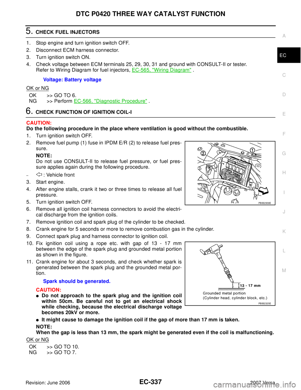
2. Remove fuel pump (1) fuse in IPDM E/R (2) to release fuel pres-
sure.
NOTE:
Do not use CONSULT-II to release fuel pressure, or fuel pres-
sure applies again during the following procedure.
– : Vehicle front
3. Start engine.
4. After engine stalls, crank it two or three times to release all fuel
pressure.
5. Turn ignition switch OFF.
6. Remove all ignition coil harness connectors to avoid the electri-
cal discharge from the ignition coils.
7. Remove ignition coil and spark plug of the cylinder to be checked.
8. Crank engine for 5 seconds or more to remove combustion gas in the cylinder.
9. Connect spark plug and harness connector to ignition coil.
10. Fix ignition coil using a rope etc. with gap of 13 - 17 mm
between the edge of the spark plug and grounded metal portion
as shown in the figure.
11. Crank engine for about 3 seconds, and check whether spark is
generated between the spark plug and the grounded metal por-
tion.
CAUTION:
�Do not approach to the spark plug and the ignition coil
within 50cm. Be careful not to get an electrical shock
while checking, because the electrical discharge voltage
becomes 20kV or more.
�It might cause to damage the ignition coil if the gap of more than 17 mm is taken.
NOTE:
When the gap is less than 13 mm, the spark might be generated even if the coil is malfunctioning.
OK or NG
OK >> GO TO 10.
NG >> GO TO 7.Voltage: Battery voltage
Spark should be generated.
PBIB2958E
PBIB2325E
Page 1608 of 2896
DTC P0850 PNP SWITCH
EC-439
C
D
E
F
G
H
I
J
K
L
MA
EC
Revision: June 20062007 Versa
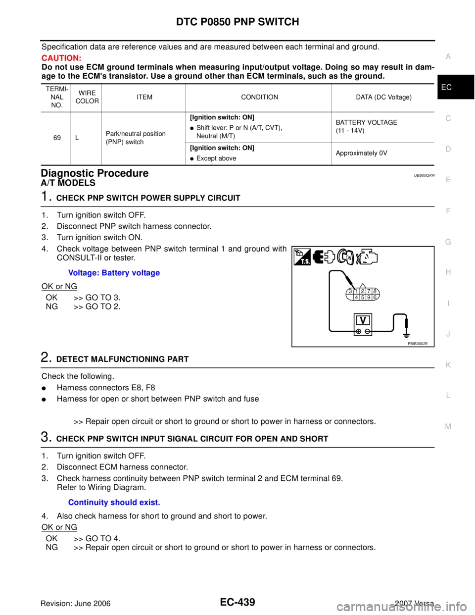
Specification data are reference values and are measured between each terminal and ground.
CAUTION:
Do not use ECM ground terminals when measuring input/output voltage. Doing so may result in dam-
age to the ECM's transistor. Use a ground other than ECM terminals, such as the ground.
Diagnostic ProcedureUBS00QKR
A/T MODELS
1. CHECK PNP SWITCH POWER SUPPLY CIRCUIT
1. Turn ignition switch OFF.
2. Disconnect PNP switch harness connector.
3. Turn ignition switch ON.
4. Check voltage between PNP switch terminal 1 and ground with
CONSULT-II or tester.
OK or NG
OK >> GO TO 3.
NG >> GO TO 2.
2. DETECT MALFUNCTIONING PART
Check the following.
�Harness connectors E8, F8
�Harness for open or short between PNP switch and fuse
>> Repair open circuit or short to ground or short to power in harness or connectors.
3. CHECK PNP SWITCH INPUT SIGNAL CIRCUIT FOR OPEN AND SHORT
1. Turn ignition switch OFF.
2. Disconnect ECM harness connector.
3. Check harness continuity between PNP switch terminal 2 and ECM terminal 69.
Refer to Wiring Diagram.
4. Also check harness for short to ground and short to power.
OK or NG
OK >> GO TO 4.
NG >> Repair open circuit or short to ground or short to power in harness or connectors.
TERMI-
NAL
NO.WIRE
COLORITEM CONDITION DATA (DC Voltage)
69 LPark/neutral position
(PNP) switch[Ignition switch: ON]
�Shift lever: P or N (A/T, CVT),
Neutral (M/T)BATTERY VOLTAGE
(11 - 14V)
[Ignition switch: ON]
�Except aboveApproximately 0V
Voltage: Battery voltage
PBIB3002E
Continuity should exist.
Page 1609 of 2896
EC-440Revision: June 2006
DTC P0850 PNP SWITCH
2007 Versa
4. CHECK PNP SWITCH
Refer to AT-101, "
Component Inspection" .
OK or NG
OK >> GO TO 5.
NG >> Replace PNP switch.
5. CHECK INTERMITTENT INCIDENT
Refer to EC-143, "
TROUBLE DIAGNOSIS FOR INTERMITTENT INCIDENT" .
>>INSPECTION END
M/T MODELS
1. CHECK PNP SWITCH POWER SUPPLY CIRCUIT
1. Turn ignition switch OFF.
2. Disconnect PNP switch harness connector.
3. Turn ignition switch ON.
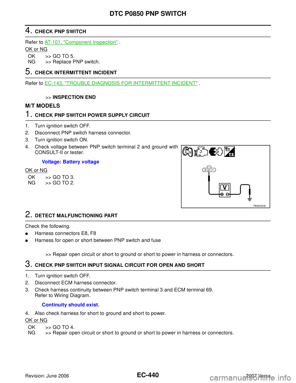
4. Check voltage between PNP switch terminal 2 and ground with
CONSULT-II or tester.
OK or NG
OK >> GO TO 3.
NG >> GO TO 2.
2. DETECT MALFUNCTIONING PART
Check the following.
�Harness connectors E8, F8
�Harness for open or short between PNP switch and fuse
>> Repair open circuit or short to ground or short to power in harness or connectors.
3. CHECK PNP SWITCH INPUT SIGNAL CIRCUIT FOR OPEN AND SHORT
1. Turn ignition switch OFF.
2. Disconnect ECM harness connector.
3. Check harness continuity between PNP switch terminal 3 and ECM terminal 69.
Refer to Wiring Diagram.
4. Also check harness for short to ground and short to power.
OK or NG
OK >> GO TO 4.
NG >> Repair open circuit or short to ground or short to power in harness or connectors.Voltage: Battery voltage
PBIB3003E
Continuity should exist.