Page 2140 of 2896
LAN-14
[CAN FUNDAMENTAL]
TROUBLE DIAGNOSIS
Revision: June 20062007 Versa
MONITOR ITEM (ON-BOARD DIAGNOSIS)
NOTE:
For some models, CAN communication diagnosis result is received from the vehicle monitor. (CONSULT-II is
not available.)
Example: Vehicle Display
ItemResult indi-
catedError counter Description
CAN_COMM
(Initial diagnosis)OK 0 Normal at present
NG 1 – 50Control unit error
(The number indicates how many times diagnosis has been
run.)
CAN_CIRC_1
(Transmission diagnosis)OK 0 Normal at present
UNKWN 1 – 50Unable to transmit for 2 seconds or more at present.
(The number indicates how many times diagnosis has been
run.)
CAN_CIRC_2 – 9
(Reception diagnosis of each unit)OK 0 Normal at present
UNKWN 1 – 50Unable to transmit for 2 seconds or more at present.
(The number indicates how many times diagnosis has been
run.)
Diagnosis not performed.
No control unit for receiving signals. (No applicable optional
parts)
Page 2141 of 2896
![NISSAN LATIO 2007 Service Repair Manual TROUBLE DIAGNOSES WORK FLOW
LAN-15
[CAN FUNDAMENTAL]
C
D
E
F
G
H
I
J
L
MA
B
LAN
Revision: June 20062007 Versa
TROUBLE DIAGNOSES WORK FLOWPFP:00004
Information Needed for Trouble DiagnosisUKS005Y8
CAN](/manual-img/5/57361/w960_57361-2140.png "NISSAN LATIO 2007 Service Repair Manual TROUBLE DIAGNOSES WORK FLOW
LAN-15
[CAN FUNDAMENTAL]
C
D
E
F
G
H
I
J
L
MA
B
LAN
Revision: June 20062007 Versa
TROUBLE DIAGNOSES WORK FLOWPFP:00004
Information Needed for Trouble DiagnosisUKS005Y8
CAN")
TROUBLE DIAGNOSES WORK FLOW
LAN-15
[CAN FUNDAMENTAL]
C
D
E
F
G
H
I
J
L
MA
B
LAN
Revision: June 20062007 Versa
TROUBLE DIAGNOSES WORK FLOWPFP:00004
Information Needed for Trouble DiagnosisUKS005Y8
CAN communication system performs trouble diagnosis with the following tools.
How to Use CAN Communication Signal ChartUKS005Y9
The CAN communication signal chart lists the signals needed for trouble diagnosis. It is useful for detecting
the root cause by finding a signal related to the symptom, and by checking transmission and reception unit.
Tool Usage
Interview sheet For filling in vehicle information and interview with customer.
Data sheet For attaching CONSULT-II data or on-board diagnosis data.
Diagnosis sheetFor detecting the root cause. (Diagnosis sheet includes system diagram for every CAN system
type)
SELECT SYSTEM
(CONSULT-II)
For checking the condition of control units and the status of CAN communication. SELF-DIAG RESULTS
(CONSULT-II)
CAN DIAG SUPPORT MNTR
(CONSULT-II)
CAN communication signal
chartFor converting information received from a customer into CAN communication signal transmission
and reception. This information can be used to judge whether a circuit between control units is nor-
mal or abnormal.
Abbreviation list For checking abbreviations in CAN communication signal chart and diagnosis sheet.
SKIB8715E
Page 2152 of 2896
![NISSAN LATIO 2007 Service Repair Manual LAN-26
[CAN FUNDAMENTAL]
TROUBLE DIAGNOSES WORK FLOW
Revision: June 20062007 Versa
Present Error — Open Circuit —
Identify the error circuit using information from the “SELECT SYSTEM” and “C](/manual-img/5/57361/w960_57361-2151.png "NISSAN LATIO 2007 Service Repair Manual LAN-26
[CAN FUNDAMENTAL]
TROUBLE DIAGNOSES WORK FLOW
Revision: June 20062007 Versa
Present Error — Open Circuit —
Identify the error circuit using information from the “SELECT SYSTEM” and “C")
LAN-26
[CAN FUNDAMENTAL]
TROUBLE DIAGNOSES WORK FLOW
Revision: June 20062007 Versa
Present Error — Open Circuit —
Identify the error circuit using information from the “SELECT SYSTEM” and “CAN DIAG SUPPORT MNTR”
screens.
1. SELECT SYSTEM: Check the items indicated in “SELECT SYSTEM”. Draw a line on the diagnosis sheet
to indicate the error circuit.
NOTE:
CAN communication line has no error if units other than Diag on CAN units are indicated. An error may be
on the power supply of the control unit, DDL1 line or DDL2 line.
a. “TRANSMISSION” which is Diag on CAN unit, is not indicated on “SELECT SYSTEM” screen. This indi-
cates that DLC is not receiving a signal from TCM. Draw a line to indicate an error between DLC and TCM
(line 1-a in the figure).
NOTE:
�Diag on CAN units are not indicated on the “SELECT SYSTEM” screen when the CAN line between
Diag on CAN unit and the data link connector is open.
�For a description of Diag on CAN, refer to LAN-6, "Diag on CAN" .
SKIB8892E
Page 2160 of 2896
![NISSAN LATIO 2007 Service Repair Manual LAN-34
[CAN FUNDAMENTAL]
TROUBLE DIAGNOSES WORK FLOW
Revision: June 20062007 Versa
2. CAN DIAG SUPPORT MNTR (with PAST): Check the CAN DIAG SUPPORT MNTR (with PAST) of units
indicating “U1000” or](/manual-img/5/57361/w960_57361-2159.png "NISSAN LATIO 2007 Service Repair Manual LAN-34
[CAN FUNDAMENTAL]
TROUBLE DIAGNOSES WORK FLOW
Revision: June 20062007 Versa
2. CAN DIAG SUPPORT MNTR (with PAST): Check the CAN DIAG SUPPORT MNTR (with PAST) of units
indicating “U1000” or")
LAN-34
[CAN FUNDAMENTAL]
TROUBLE DIAGNOSES WORK FLOW
Revision: June 20062007 Versa
2. CAN DIAG SUPPORT MNTR (with PAST): Check the CAN DIAG SUPPORT MNTR (with PAST) of units
indicating “U1000” or “U1001” on SELF-DIAG RESULTS. Draw a line on the diagnosis sheet to indicate
the possible error circuit.
NOTE:
For the details of each indication on CAN DIAG SUPPORT MNTR, refer to LAN-44, "
CAN Diagnostic Sup-
port Monitor" .
a. Reception item of “ENGINE”: “VDC/TCS/ABS”, “3” is indicated in the “PAST”. This means ECM could not
receive the signal from ABS in the past. Draw a line between ECM and ABS (line 2-a in the figure).
b. Reception item of “METER”: “VDC/TCS/ABS”, “3” is indicated in the “PAST”. This means M&A could not
receive the signal from ABS in the past. Draw a line between M&A and ABS (line 2-b in the figure).
c. Reception item of “TRANSMISSION”: “VDC/TCS/ABS”, “3” is indicated in the “PAST”. This means TCM
could not receive the signal from ABS in the past. Draw a line between TCM and ABS (line 2-c in the fig-
ure).
SKIB8732E
Page 2167 of 2896
HOW TO USE THIS SECTION
LAN-41
[CAN]
C
D
E
F
G
H
I
J
L
MA
B
LAN
Revision: June 20062007 Versa
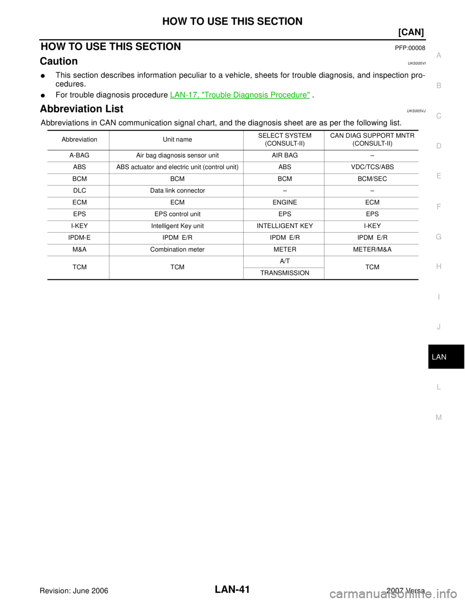
HOW TO USE THIS SECTIONPFP:00008
CautionUKS005VI
�This section describes information peculiar to a vehicle, sheets for trouble diagnosis, and inspection pro-
cedures.
�For trouble diagnosis procedure LAN-17, "Trouble Diagnosis Procedure" .
Abbreviation ListUKS005VJ
Abbreviations in CAN communication signal chart, and the diagnosis sheet are as per the following list.
Abbreviation Unit nameSELECT SYSTEM
(CONSULT-II)CAN DIAG SUPPORT MNTR
(CONSULT-II)
A-BAG Air bag diagnosis sensor unit AIR BAG –
ABS ABS actuator and electric unit (control unit) ABS VDC/TCS/ABS
BCM BCM BCM BCM/SEC
DLC Data link connector – –
ECM ECM ENGINE ECM
EPS EPS control unit EPS EPS
I-KEY Intelligent Key unit INTELLIGENT KEY I-KEY
IPDM-E IPDM E/R IPDM E/R IPDM E/R
M&A Combination meter METER METER/M&A
TCM TCMA/T
TCM
TRANSMISSION
Page 2170 of 2896
![NISSAN LATIO 2007 Service Repair Manual LAN-44
[CAN]
TROUBLE DIAGNOSIS
Revision: June 20062007 Versa
TROUBLE DIAGNOSISPFP:00004
CAN Diagnostic Support MonitorUKS005WF
Use “CAN DIAG SUPPORT MNTR” for detecting the root cause.
MONITOR ITE](/manual-img/5/57361/w960_57361-2169.png "NISSAN LATIO 2007 Service Repair Manual LAN-44
[CAN]
TROUBLE DIAGNOSIS
Revision: June 20062007 Versa
TROUBLE DIAGNOSISPFP:00004
CAN Diagnostic Support MonitorUKS005WF
Use “CAN DIAG SUPPORT MNTR” for detecting the root cause.
MONITOR ITE")
LAN-44
[CAN]
TROUBLE DIAGNOSIS
Revision: June 20062007 Versa
TROUBLE DIAGNOSISPFP:00004
CAN Diagnostic Support MonitorUKS005WF
Use “CAN DIAG SUPPORT MNTR” for detecting the root cause.
MONITOR ITEM LIST (CONSULT-II)
ECM
0: Error at present, 1 – 39: Error in the past (Number means the number of times the ignition switch is turned OFF→ON)
*: 39 or higher number is fixed at 39 until the self-diagnosis result is erased.
BCM
NOTE:
Replace the unit when “NG” is indicated on the “INITIAL DIAG”.
EPS control unit
SELECT SYS-
TEMCAN DIAG SUP-
PORT MNTRDescriptionNormal Error
PRSNT PAST PRSNT PAST
ENGINETRANSMIT DIAG Signal transmission status
OKOK
or
1 – 39
*UNKWN 0 VDC/TCS/ABSSignal receiving status from the ABS actu-
ator and electric unit (control unit)
METER/M&ASignal receiving status from the combina-
tion meter
BCM/SEC Signal receiving status from the BCM
ICC
Not used even though indicated
HVAC
TCM Signal receiving status from the TCM
OKOK
or
1 – 39
*UNKWN 0 EPSSignal receiving status from the EPS con-
trol unit
IPDM E/R Signal receiving status from the IPDM E/R
e4WD
Not used even though indicated
AWD/4WD
SELECT SYS-
TEMCAN DIAG SUP-
PORT MNTRDescriptionNormal Error
PRSNT
BCMINITIAL DIAG Status of CAN controller
OKNG
TRANSMIT DIAG Signal transmission status
UNKWN ECM Signal receiving status from the ECM
IPDM E/R Signal receiving status from the IPDM E/R
METER/M&A Signal receiving status from the combination meter
I-KEY Signal receiving status from the Intelligent Key unit
TCM Not used even though indicated
SELECT SYS-
TEMCAN DIAG SUP-
PORT MNTRDescriptionNormal Error
PRSNT
EPSTRANSMIT DIAG Signal transmission status
OK UNKWN ECM Signal receiving status from the ECM
VDC/TCS/ABSSignal receiving status from the ABS actuator and electric unit
(control unit)
METER/M&A Signal receiving status from the combination meter
Page 2171 of 2896
![NISSAN LATIO 2007 Service Repair Manual TROUBLE DIAGNOSIS
LAN-45
[CAN]
C
D
E
F
G
H
I
J
L
MA
B
LAN
Revision: June 20062007 Versa
Intelligent Key unit
0: Error at present, 1 – 39: Error in the past (Number means the number of times the igni](/manual-img/5/57361/w960_57361-2170.png "NISSAN LATIO 2007 Service Repair Manual TROUBLE DIAGNOSIS
LAN-45
[CAN]
C
D
E
F
G
H
I
J
L
MA
B
LAN
Revision: June 20062007 Versa
Intelligent Key unit
0: Error at present, 1 – 39: Error in the past (Number means the number of times the igni")
TROUBLE DIAGNOSIS
LAN-45
[CAN]
C
D
E
F
G
H
I
J
L
MA
B
LAN
Revision: June 20062007 Versa
Intelligent Key unit
0: Error at present, 1 – 39: Error in the past (Number means the number of times the ignition switch is turned OFF→ON)
*: 39 or higher number is fixed at 39 until the self-diagnosis result is erased.
Combination meter
0: Error at present, 1 – 39: Error in the past (Number means the number of times the ignition switch is turned OFF→ON)
*: 39 or higher number is fixed at 39 until the self-diagnosis result is erased.
ABS actuator and electric unit (control unit)
CAUTION:
Never replace the unit even when “NG” is indicated on the “INITIAL DIAG” at this stage. Follow the trouble diagnosis proce-
dures. SELECT SYS-
TEMCAN DIAG SUP-
PORT MNTRDescriptionNormal Error
PRSNT PAST PRSNT PAST
INTELLIGENT
KEYTRANSMIT DIAG Signal transmission status
OKOK
or
1 – 39
*UNKWN 0 ECM Signal receiving status from the ECM
METER/M&ASignal receiving status from the combina-
tion meter
BCM/SEC Signal receiving status from the BCM
SELECT SYS-
TEMCAN DIAG SUP-
PORT MNTRDescriptionNormal Error
PRSNT PAST PRSNT PAST
METERTRANSMIT DIAG Signal transmission status
OKOK
or
1 – 39
*UNKWN 0 ECM Signal receiving status from the ECM
TCM Signal receiving status from the TCM
BCM/SEC Signal receiving status from the BCM
VDC/TCS/ABSSignal receiving status from the ABS actu-
ator and electric unit (control unit)
IPDM E/R Signal receiving status from the IPDM E/R
DISPLAY Not used even though indicated
I-KEYSignal receiving status from the Intelligent
Key unit
OKOK
or
1 – 39
*UNKWN 0
EPSSignal receiving status from the EPS con-
trol unit
AWD /4 WD
Not used even though indicated e4WD
ICC
LANE KEEP
TIRE-P
SELECT SYS-
TEMCAN DIAG SUP-
PORT MNTRDescriptionNormal Error
PRSNT
ABSINITIAL DIAG Status of CAN controller
OKNG
Caution
TRANSMIT DIAG Signal transmission status
UNKWN
ECM Signal receiving status from the ECM
Page 2172 of 2896
![NISSAN LATIO 2007 Service Repair Manual LAN-46
[CAN]
TROUBLE DIAGNOSIS
Revision: June 20062007 Versa
TCM (Models with A/T)
NOTE:
Replace the unit when “NG” is indicated on the “INITIAL DIAG”.
TCM (Models with CVT)
0: Error at presen](/manual-img/5/57361/w960_57361-2171.png "NISSAN LATIO 2007 Service Repair Manual LAN-46
[CAN]
TROUBLE DIAGNOSIS
Revision: June 20062007 Versa
TCM (Models with A/T)
NOTE:
Replace the unit when “NG” is indicated on the “INITIAL DIAG”.
TCM (Models with CVT)
0: Error at presen")
LAN-46
[CAN]
TROUBLE DIAGNOSIS
Revision: June 20062007 Versa
TCM (Models with A/T)
NOTE:
Replace the unit when “NG” is indicated on the “INITIAL DIAG”.
TCM (Models with CVT)
0: Error at present, 1 – 39: Error in the past (Number means the number of times the ignition switch is turned OFF→ON)
*: 39 or higher number is fixed at 39 until the self-diagnosis result is erased.
IPDM E/R
0: Error at present, 1 – 39: Error in the past (Number means the number of times the ignition switch is turned OFF→ON)
*: 39 or higher number is fixed at 39 until the self-diagnosis result is erased.SELECT SYS-
TEMCAN DIAG SUP-
PORT MNTRDescriptionNormal Error
PRSNT
A/TINITIAL DIAG Status of CAN controller
OKNG
TRANSMIT DIAG Signal transmission status
UNKWN
ECM Signal receiving status from the ECM
VDC/TCS/ABS Not used even though indicated
METER/M&A Signal receiving status from the combination meter OK UNKWN
ICC/e4WD Not used even though indicated
SELECT SYS-
TEMCAN DIAG SUP-
PORT MNTRDescriptionNormal Error
PRSNT PAST PRSNT PAST
TRANSMISSIONTRANSMIT DIAG Signal transmission status
OKOK
or
1 – 39
*UNKWN 0 ECM Signal receiving status from the ECM
VDC/TCS/ABSSignal receiving status from the ABS actu-
ator and electric unit (control unit)
METER/M&ASignal receiving status from the combina-
tion meter
BCM/SEC
Not used even though indicated ICC
e4WD
AWD/4WD
SELECT SYS-
TEMCAN DIAG SUP-
PORT MNTRDescriptionNormal Error
PRSNT PAST PRSNT PAST
IPDM E/RTRANSMIT DIAG Signal transmission status
OKOK
or
1 – 39
*UNKWN 0 ECM Signal receiving status from the ECM
BCM/SEC Signal receiving status from the BCM
![NISSAN LATIO 2007 Service Repair Manual LAN-14
[CAN FUNDAMENTAL]
TROUBLE DIAGNOSIS
Revision: June 20062007 Versa
MONITOR ITEM (ON-BOARD DIAGNOSIS)
NOTE:
For some models, CAN communication diagnosis result is received from the vehicle monito](/manual-img/5/57361/w960_57361-2139.png "NISSAN LATIO 2007 Service Repair Manual LAN-14
[CAN FUNDAMENTAL]
TROUBLE DIAGNOSIS
Revision: June 20062007 Versa
MONITOR ITEM (ON-BOARD DIAGNOSIS)
NOTE:
For some models, CAN communication diagnosis result is received from the vehicle monito")