Page 78 of 130
RF-78
SOFT TOP
Revision: 2006 November2007 350Z
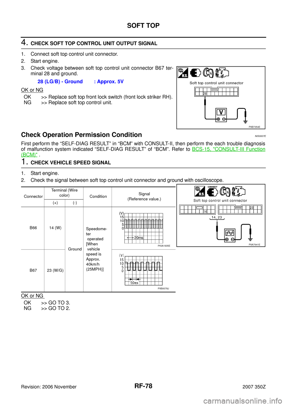
4. CHECK SOFT TOP CONTROL UNIT OUTPUT SIGNAL
1. Connect soft top control unit connector.
2. Start engine.
3. Check voltage between soft top control unit connector B67 ter-
minal 28 and ground.
OK or NG
OK >> Replace soft top front lock switch (front lock striker RH).
NG >> Replace soft top control unit.
Check Operation Permission ConditionNIS0007E
First perform the “SELF-DIAG RESULT” in “BCM” with CONSULT-II, then perform the each trouble diagnosis
of malfunction system indicated “SELF-DIAG RESULT” of “BCM”. Refer to BCS-15, "
CONSULT-III Function
(BCM)" .
1. CHECK VEHICLE SPEED SIGNAL
1. Start engine.
2. Check the signal between soft top control unit connector and ground with oscilloscope.
OK or NG
OK >> GO TO 3.
NG >> GO TO 2.28 (LG/B) - Ground : Approx. 5V
PIIB7354E
ConnectorTerminal (Wire
color)
ConditionSignal
(Reference value.)
(+) (-)
B66 14 (W)
GroundSpeedome-
ter
operated
[When
vehicle
speed is
Approx.
40km/h
(25MPH)]
B67 23 (W/G)
PIIA7941EPKIA1935E
PIIB0078J
Page 79 of 130
SOFT TOP
RF-79
C
D
E
F
G
H
J
K
L
MA
B
RF
Revision: 2006 November2007 350Z
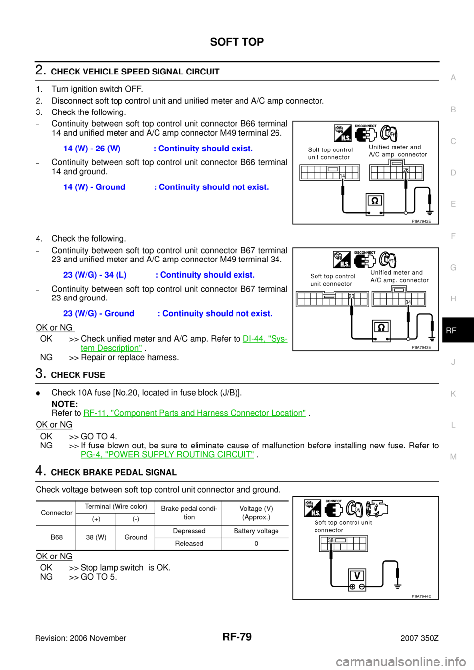
2. CHECK VEHICLE SPEED SIGNAL CIRCUIT
1. Turn ignition switch OFF.
2. Disconnect soft top control unit and unified meter and A/C amp connector.
3. Check the following.
–Continuity between soft top control unit connector B66 terminal
14 and unified meter and A/C amp connector M49 terminal 26.
–Continuity between soft top control unit connector B66 terminal
14 and ground.
4. Check the following.
–Continuity between soft top control unit connector B67 terminal
23 and unified meter and A/C amp connector M49 terminal 34.
–Continuity between soft top control unit connector B67 terminal
23 and ground.
OK or NG
OK >> Check unified meter and A/C amp. Refer to DI-44, "Sys-
tem Description" .
NG >> Repair or replace harness.
3. CHECK FUSE
�Check 10A fuse [No.20, located in fuse block (J/B)].
NOTE:
Refer to RF-11, "
Component Parts and Harness Connector Location" .
OK or NG
OK >> GO TO 4.
NG >> If fuse blown out, be sure to eliminate cause of malfunction before installing new fuse. Refer to
PG-4, "
POWER SUPPLY ROUTING CIRCUIT" .
4. CHECK BRAKE PEDAL SIGNAL
Check voltage between soft top control unit connector and ground.
OK or NG
OK >> Stop lamp switch is OK.
NG >> GO TO 5.14 (W) - 26 (W) : Continuity should exist.
14 (W) - Ground : Continuity should not exist.
PIIA7942E
23 (W/G) - 34 (L) : Continuity should exist.
23 (W/G) - Ground : Continuity should not exist.
PIIA7943E
ConnectorTerminal (Wire color)
Brake pedal condi-
tionVoltage (V)
(Approx.)
(+) (-)
B68 38 (W) GroundDepressed Battery voltage
Released 0
PIIA7944E
Page 83 of 130
SOFT TOP
RF-83
C
D
E
F
G
H
J
K
L
MA
B
RF
Revision: 2006 November2007 350Z
Check Passenger Side Seat Operate Signal 2NIS0007K
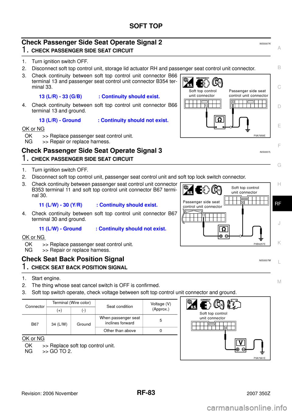
1. CHECK PASSENGER SIDE SEAT CIRCUIT
1. Turn ignition switch OFF.
2. Disconnect soft top control unit, storage lid actuator RH and passenger seat control unit connector.
3. Check continuity between soft top control unit connector B66
terminal 13 and passenger seat control unit connector B354 ter-
minal 33.
4. Check continuity between soft top control unit connector B66
terminal 13 and ground.
OK or NG
OK >> Replace passenger seat control unit.
NG >> Repair or replace harness.
Check Passenger Side Seat Operate Signal 3NIS0007L
1. CHECK PASSENGER SIDE SEAT CIRCUIT
1. Turn ignition switch OFF.
2. Disconnect soft top control unit, passenger seat control unit and soft top lock switch connector.
3. Check continuity between passenger seat control unit connector
B353 terminal 11 and soft top control unit connector B67 termi-
nal 30.
4. Check continuity between soft top control unit connector B67
terminal 30 and ground.
OK or NG
OK >> Replace passenger seat control unit.
NG >> Repair or replace harness.
Check Seat Back Position SignalNIS0007M
1. CHECK SEAT BACK POSITION SIGNAL
1. Start engine.
2. The thing whose seat cancel switch is OFF is confirmed.
3. Soft top switch operate, check voltage between soft top control unit connector and ground.
OK or NG
OK >> Replace soft top control unit.
NG >> GO TO 2.13 (L/R) - 33 (G/B) : Continuity should exist.
13 (L/R) - Ground : Continuity should not exist.
PIIA7959E
11 (L/W) - 30 (Y/R) : Continuity should exist.
11 (L/W) - Ground : Continuity should not exist.
PIIB9257E
ConnectorTerminal (Wire color)
Seat conditionVoltage (V)
(Approx.)
(+) (-)
B67 34 (L/W) GroundWhen passenger seat
inclines forward5
Other than above 0
PIIA7961E
Page 85 of 130
SOFT TOP
RF-85
C
D
E
F
G
H
J
K
L
MA
B
RF
Revision: 2006 November2007 350Z
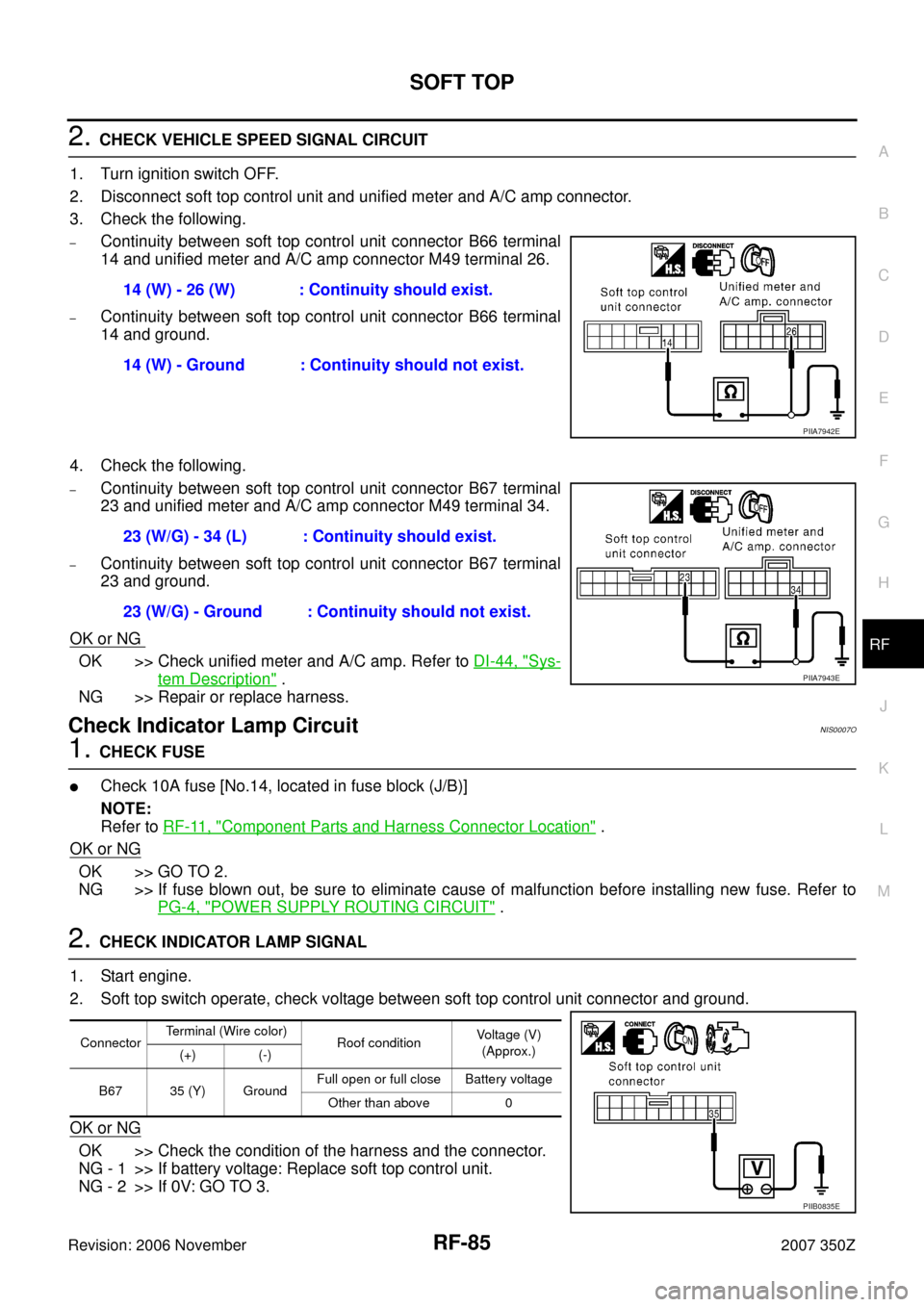
2. CHECK VEHICLE SPEED SIGNAL CIRCUIT
1. Turn ignition switch OFF.
2. Disconnect soft top control unit and unified meter and A/C amp connector.
3. Check the following.
–Continuity between soft top control unit connector B66 terminal
14 and unified meter and A/C amp connector M49 terminal 26.
–Continuity between soft top control unit connector B66 terminal
14 and ground.
4. Check the following.
–Continuity between soft top control unit connector B67 terminal
23 and unified meter and A/C amp connector M49 terminal 34.
–Continuity between soft top control unit connector B67 terminal
23 and ground.
OK or NG
OK >> Check unified meter and A/C amp. Refer to DI-44, "Sys-
tem Description" .
NG >> Repair or replace harness.
Check Indicator Lamp CircuitNIS0007O
1. CHECK FUSE
�Check 10A fuse [No.14, located in fuse block (J/B)]
NOTE:
Refer to RF-11, "
Component Parts and Harness Connector Location" .
OK or NG
OK >> GO TO 2.
NG >> If fuse blown out, be sure to eliminate cause of malfunction before installing new fuse. Refer to
PG-4, "
POWER SUPPLY ROUTING CIRCUIT" .
2. CHECK INDICATOR LAMP SIGNAL
1. Start engine.
2. Soft top switch operate, check voltage between soft top control unit connector and ground.
OK or NG
OK >> Check the condition of the harness and the connector.
NG - 1 >> If battery voltage: Replace soft top control unit.
NG - 2 >> If 0V: GO TO 3.14 (W) - 26 (W) : Continuity should exist.
14 (W) - Ground : Continuity should not exist.
PIIA7942E
23 (W/G) - 34 (L) : Continuity should exist.
23 (W/G) - Ground : Continuity should not exist.
PIIA7943E
ConnectorTerminal (Wire color)
Roof conditionVoltage (V)
(Approx.)
(+) (-)
B67 35 (Y) GroundFull open or full close Battery voltage
Other than above 0
PIIB0835E
Page 88 of 130
RF-88
SOFT TOP
Revision: 2006 November2007 350Z
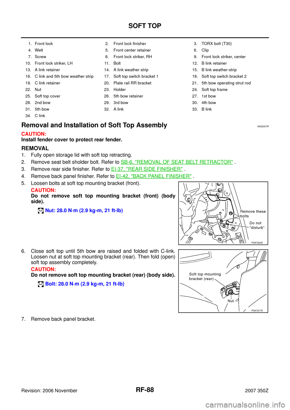
Removal and Installation of Soft Top AssemblyNIS0007R
CAUTION:
Install fender cover to protect rear fender.
REMOVAL
1. Fully open storage lid with soft top retracting.
2. Remove seat belt sholder bolt. Refer to SB-6, "
REMOVAL OF SEAT BELT RETRACTOR" .
3. Remove rear side finisher. Refer to EI-37, "
REAR SIDE FINISHER" .
4. Remove back panel finisher. Refer to EI-42, "
BACK PANEL FINISHER" .
5. Loosen bolts at soft top mounting bracket (front).
CAUTION:
Do not remove soft top mounting bracket (front) (body
side).
6. Close soft top until 5th bow are raised and folded with C-link.
Loosen nut at soft top mounting bracket (rear). Then fold (open)
soft top assembly completely.
CAUTION:
Do not remove soft top mounting bracket (rear) (body side).
7. Remove back panel bracket.
1. Front lock 2. Front lock finisher 3. TORX bolt (T30)
4. Welt 5. Front center retainer 6. Clip
7. Screw 8. Front lock striker, RH 9. Front lock striker, center
10. Front lock striker, LH 11. Bolt 12. B link retainer
13. A link retainer 14. A link weather strip 15. B link weather-strip
16. C link and 5th bow weather strip 17. Soft top switch bracket 1 18. Soft top switch bracket 2
19. C link retainer 20. Plate rail RR bracket 21. 5th bow operating strut rod
22. Nut 23. Holder 24. Soft top frame
25. Soft top cover 26. 5th bow retainer 27. 1st bow
28. 2nd bow 29. 3rd bow 30. 4th bow
31. 5th bow 32. A link 33. B link
34. C link
Nut: 28.0 N·m (2.9 kg-m, 21 ft-lb)
PIIA7824E
Bolt: 28.0 N·m (2.9 kg-m, 21 ft-lb)
PIIA7877E
Page 91 of 130
SOFT TOP
RF-91
C
D
E
F
G
H
J
K
L
MA
B
RF
Revision: 2006 November2007 350Z
5. Open soft top assembly.
6. Protect the limit switch contact around the rotation axis of the 5th
bow on the left side of soft top with tape.
7. Remove welt on the rear end of front lock finisher.
8. Remove left/right clips on the front end of front lock finisher.
9. Pull up front lock lever, and then disengage clips to remove front
lock finisher.
PIIB1288E
PIIB1286E
PIIA7809E
PIIB1287E
PIIB1303E
Page 106 of 130
RF-106
SOFT TOP
Revision: 2006 November2007 350Z
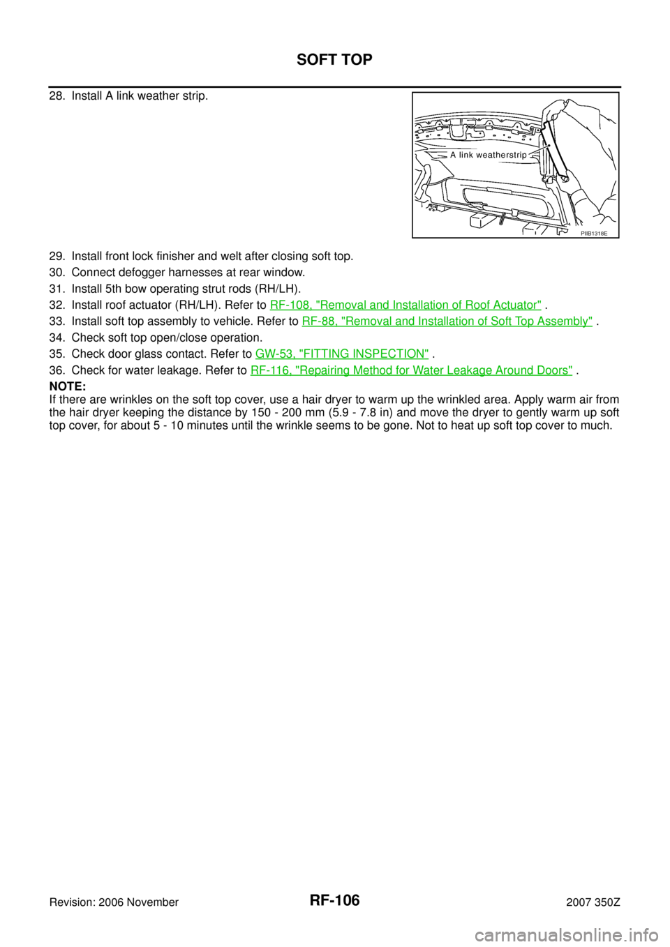
28. Install A link weather strip.
29. Install front lock finisher and welt after closing soft top.
30. Connect defogger harnesses at rear window.
31. Install 5th bow operating strut rods (RH/LH).
32. Install roof actuator (RH/LH). Refer to RF-108, "
Removal and Installation of Roof Actuator" .
33. Install soft top assembly to vehicle. Refer to RF-88, "
Removal and Installation of Soft Top Assembly" .
34. Check soft top open/close operation.
35. Check door glass contact. Refer to GW-53, "
FITTING INSPECTION" .
36. Check for water leakage. Refer to RF-116, "
Repairing Method for Water Leakage Around Doors" .
NOTE:
If there are wrinkles on the soft top cover, use a hair dryer to warm up the wrinkled area. Apply warm air from
the hair dryer keeping the distance by 150 - 200 mm (5.9 - 7.8 in) and move the dryer to gently warm up soft
top cover, for about 5 - 10 minutes until the wrinkle seems to be gone. Not to heat up soft top cover to much.
PIIB1318E
Page 108 of 130
RF-108
SOFT TOP
Revision: 2006 November2007 350Z
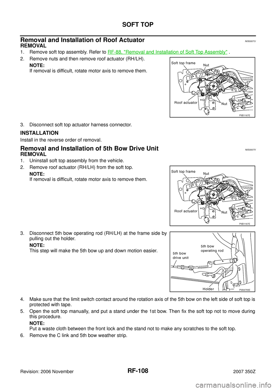
Removal and Installation of Roof ActuatorNIS0007U
REMOVAL
1. Remove soft top assembly. Refer to RF-88, "Removal and Installation of Soft Top Assembly" .
2. Remove nuts and then remove roof actuator (RH/LH).
NOTE:
If removal is difficult, rotate motor axis to remove them.
3. Disconnect soft top actuator harness connector.
INSTALLATION
Install in the reverse order of removal.
Removal and Installation of 5th Bow Drive UnitNIS0007V
REMOVAL
1. Uninstall soft top assembly from the vehicle.
2. Remove roof actuator (RH/LH) from the soft top.
NOTE:
If removal is difficult, rotate motor axis to remove them.
3. Disconnect 5th bow operating rod (RH/LH) at the frame side by
pulling out the holder.
NOTE:
This step will make the 5th bow up and down motion easier.
4. Make sure that the limit switch contact around the rotation axis of the 5th bow on the left side of soft top is
protected with tape.
5. Open the soft top manually, and put a stand under the 1st bow. Then fix the soft top not to move during
this procedure.
NOTE:
Put a waste cloth between the front lock and the stand not to make any scratches to the soft top.
6. Remove the C link and 5th bow weather strip.
PIIB1167E
PIIB1167E
PIIA9755E