Page 9 of 40
ROAD WHEEL TIRE ASSEMBLY
WT-9
C
D
F
G
H
I
J
K
L
MA
B
WT
Revision: 2006 November2007 350Z
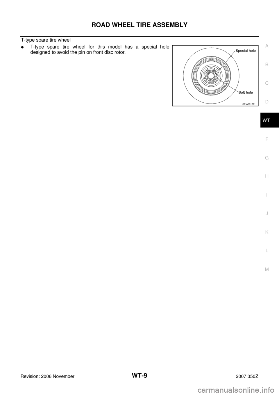
T-type spare tire wheel
�T-type spare tire wheel for this model has a special hole
designed to avoid the pin on front disc rotor.
SEIA0317E
Page 10 of 40
WT-10
TIRE PRESSURE MONITORING SYSTEM
Revision: 2006 November2007 350Z
TIRE PRESSURE MONITORING SYSTEMPFP:40300
System ComponentsNES0001A
System DescriptionNES0001B
TRANSMITTER
A sensor-transmitter (1) integrated with a valve is installed on a
wheel (2), and transmits a detected air pressure signal in the form of
a radio wave.
REMOTE KEYLESS ENTRY RECEIVER
The remote keyless entry receiver receives the air pressure signal
transmitted by the transmitter in each wheel.
SEIA0582E
: Outside
SEIA0768E
SEIA0431E
Page 21 of 40

TROUBLE DIAGNOSIS
WT-21
C
D
F
G
H
I
J
K
L
MA
B
WT
Revision: 2006 November2007 350Z
ID Registration ProcedureNES0001G
ID REGISTRATION WITH ACTIVATION TOOL
This procedure must be done after replacing or rotating wheels, replacing transmitter or BCM.
1. Select “AIR PRESSURE MONITOR” on “SELECT WORK ITEM”.
2. Touch “WORK SUPPORT” on “SELECT DIAG MODE” screen, and select “ID REGIST”.
3. With the activation tool (J-45295) pushed against the front-left
transmitter position of the tire air valve, press the button then
keep 5 seconds.
4. Register the IDs in order from FR LH, FR RH, RR RH to RR LH.
When ID registration of each wheel has been completed, a
buzzer sounds and turn signal lamp (LH/ RH) blinks.
5. After completing all ID registrations, press “END” to complete the procedure.
NOTE:
Be sure to register the IDs in order from FR LH, FR RH, RR RH, to RR LH, or the self-diagnostic results dis-
play will not function properly.
ID REGISTRATION WITHOUT ACTIVATION TOOL
This procedure must be done after replacing or rotating wheels, replacing transmitter or BCM.
1. Select “AIR PRESSURE MONITOR” on “SELECT WORK ITEM”.
2. Touch “WORK SUPPORT” on “SELECT DIAG MODE” screen, and select “ID REGIST”.
3. Adjust the tire pressure to the values shown in the table below for ID registration, and drive the vehicle at
40 km/h (25 MPH) or more for a few minutes.
4. After completing all ID registrations, press “END” to complete the procedure.
46 (PU/W) Turn signal (right)
�Ignition switch ON
�Combination switch is turn right
ON
52 (B) GND — 0V
55 (R) Battery power supply (F/L) Always Battery voltage (12V)Terminal
(Wire color)Item ConditionVoltage (V)
Approx. value
SKIA3009J
Activation tire position Buzzer Turn signal lamp CONSULT-III
1 Front LH Once
2 times flashing“Red”
↓
“Green” 2 Front RH 2 times
3 Rear RH 3 times
4 Rear LH 4 times
SEIA0460E
Tire position
Tire pressure kPa (kg/cm2 , psi)
Front − Left 240 (2.4, 34)
Front − Right 220 (2.2, 31)
Rear − Right 200 (2.0, 29)
Rear − Left 180 (1.8, 26)
Activation tire position CONSULT-III
Front LH
“Red”
↓
“Green” Front RH
Rear RH
Rear LH
Page 22 of 40
\" .
Transmitter Wake Up OperationNES0001H
WITH A")
WT-22
TROUBLE DIAGNOSIS
Revision: 2006 November2007 350Z
5. Inflate all tires to proper pressure. Refer to WT-39, "SERVICE DATA AND SPECIFICATIONS (SDS)" .
Transmitter Wake Up OperationNES0001H
WITH ACTIVATION TOOL
1. With the activation tool (J-45295) pushed against the front-left
transmitter, press the button for 5 seconds.
�When ignition switch ON, as the low tire pressure warning
lamp blinks per the follow diagram, the respective transmitter
then must be woken up.
2. Register the ID of wheel that warning lamp flashes. When wake up of registered wheel has been com-
pleted, turn signal lamp flashes two times.
3. After completing wake up of all transmitters, make sure low tire pressure warning lamp goes out.
CONSULT-III Function (BCM)NES000DL
CONSULT-III MAIN FUNCTION
CONSULT-III can display each diagnostic item using the diagnostic test modes shown following.
WORK SUPPORT MODE
ID Read
The registered ID number is displayed.
ID Regist
Refer to WT-21, "ID Registration Procedure" .
SEIA0460E
SEIA0378E
BCM diagnosis part Mode Function
Air pressure monitorWork supportThis mode enables a technician to adjust some devices faster and more accurately
by following the indications on CONSULT-III.
Self-diagnostic results Self-diagnostic results can be read and erased quickly.
Data monitor Input/Output data in the control unit can be read.
Active testDiagnostic Test Mode in with CONSULT-III drives some actuators apart from the
control unit (BCM) and also shifts some parameters in a specified range.
Page 26 of 40
NES000A4
DESCRIPTION
During driving, the low tire pressure warning system r")
WT-26
TROUBLE DIAGNOSIS
Revision: 2006 November2007 350Z
Diagnosis Procedure with Warning Lamp Function (Without CONSULT-III)NES000A4
DESCRIPTION
During driving, the low tire pressure warning system receives the signal transmitted from the transmitter
installed in each wheel. The control unit (BCM) of this system has pressure judgement and trouble diagnosis
functions.
FUNCTION
When the low tire pressure warning system detects low inflation pressure or another unusual symptom, the
warning lamps in the combination meter comes on. To start the self-diagnostic results mode, ground terminal
of the tire pressure warning check connector. The malfunction location is indicated by the warning lamp flash-
ing. Refer to PG-41, "
HARNESS" .
MALFUNCTION CODE CHART
Code (warning lamp blinks) Diagnosis item Reference
15
Front-left tire pressure drops to 190 kPa (1.90 kg/cm
2 , 28 psi) or less.
— 16
Front-right tire pressure drops to 190 kPa (1.90 kg/cm
2 , 28 psi) or less.
17
Rear-right tire pressure drops to 190 kPa (1.90 kg/cm
2 , 28 psi) or less.
18
Rear-left tire pressure drops to 190 kPa (1.90 kg/cm
2 , 28 psi) or less.
21 Transmitter no data (front - left)
WT-30
22 Transmitter no data (front - right)
23 Transmitter no data (rear - right)
24 Transmitter no data (rear - left)
31 Transmitter checksum error (front - left)
WT-30
32 Transmitter checksum error (front - right)
33 Transmitter checksum error (rear - right)
34 Transmitter checksum error (rear - left)
35 Transmitter pressure data error (front - left)
WT-31
36 Transmitter pressure data error (front - right)
37 Transmitter pressure data error (rear - right)
38 Transmitter pressure data error (rear - left)
41 Transmitter function code error (front - left)
WT-30
42 Transmitter function code error (front - right)
43 Transmitter function code error (rear - right)
44 Transmitter function code error (rear - left)
45 Transmitter battery voltage low (front - left)
WT-30
46 Transmitter battery voltage low (front - right)
47 Transmitter battery voltage low (rear - right)
48 Transmitter battery voltage low (rear - left)
52 Vehicle speed signalWT-32
Page 27 of 40
Low tire pressure warning la")
TROUBLE DIAGNOSIS
WT-27
C
D
F
G
H
I
J
K
L
MA
B
WT
Revision: 2006 November2007 350Z
LOW TIRE PRESSURE WARNING LAMP SYMPTOM CHART
Diagnosis
ItemSymptom
(Ignition switch ON)Low tire pressure warning lamp Cause Action
Low tire pres-
sure warning
lampWarning light comes
on immediately and
turns off after 1 sec-
ond.All wheel transmit-
ters are “activated”
(working).None (system OK)
Warning light blinks
on for 2 seconds,
then turns off for 0.2
seconds-repeats.All wheel transmit-
ters are not acti-
vated.Activate all wheel transmit-
ters. Refer to WT-22,
"Transmitter Wake Up Oper-
ation" .
Warning light blinks 1
time.Front LH wheel
transmitter is not
activated.Activate front LH wheel
transmitter. Refer to WT-22,
"Transmitter Wake Up Oper-
ation" .
Warning light blinks 2
times.Front RH wheel
transmitter is not
activated.Activate front RH wheel
transmitter. Refer to WT-22,
"Transmitter Wake Up Oper-
ation" .
Warning light blinks 3
times.Rear RH wheel
transmitter is not
activated.Activate rear RH wheel
transmitter. Refer to WT-22,
"Transmitter Wake Up Oper-
ation" .
SEIA0592E
SEIA0593E
PEIA0073E
SEIA0595E
SEIA0596E
Page 28 of 40

WT-28
TROUBLE DIAGNOSIS
Revision: 2006 November2007 350Z
NOTE:
If more than one wheel transmitter is NOT activated, the warning light blinking patterns for those wheels will combine. (Example: one
blink/OFF/three blinks = Rear LH and Rear RH transmitters are not activated.)Low tire pres-
sure warning
lampWarning light blinks 4
times.Rear LH wheel trans-
mitter is not acti-
vated.Activate rear LH wheel
transmitter. Refer to WT-22,
"Transmitter Wake Up Oper-
ation" .
Warning light comes
on and does not turn
off.Tire pressure is low.Check tire pressure with
CONSULT-III. Refer to WT-
24, "DATA MONITOR
MODE" .
The fuse for combi-
nation meter from
battery is pulled out.Check the fuse for combina-
tion meter from battery.
Install or replace (if needed).
BCM connector
pulled out.Check BCM connector. Re-
connect if needed.
Low tire pressure or
tire pressure moni-
toring system mal-
function.
�Perform CONSULT-III
Self- Diagnosis. Refer to
WT-23, "
SELF-DIAG
RESULTS MODE" .
–Perform ID Registration if
needed. Refer to WT-21,
"ID Registration Proce-
dure" .
Turn signal
lampTurn signal lamp
does not flash 2
times or horn does
not sound after trans-
mitter activation.—1. Tool J-45295 (spe-
cial service tool)
battery low.
2. Ignition OFF dur-
ing activation.
3. Tool J-45295 (spe-
cial service tool)
not positioned cor-
rectly.
4. Transmitters
already activated.1. Install new battery.
2. Make sure ignition is ON
during activation.
3. Position tool correctly dur-
ing activation.
4. None Diagnosis
ItemSymptom
(Ignition switch ON)Low tire pressure warning lamp Cause Action
SEIA0597E
SEIA0598E
Page 38 of 40
 is 270 degree from mounting head (2) when second side of
tire i")
WT-38
REMOVAL AND INSTALLATION
Revision: 2006 November2007 350Z
3. Place wheel on turntable of tire machine. Ensure that transmitter
(1) is 270 degree from mounting head (2) when second side of
tire is fitted.
NOTE:
Do not touch transmitter at mounting head.
4. Lubricate tire well and fit second side of tire as normal. Ensure that tire does not rotate relative to rim.
5. Inflate tire and fit to appropriate wheel position.
REMOTE KEYLESS ENTRY RECEIVER
Removal
1. Remove the front kicking plate LH. Refer to EI-35, "BODY SIDE TRIM" .
2. Remove the dash side finisher LH. Refer to EI-35, "
BODY SIDE TRIM" .
3. Remove the instrument lower cover. Refer to IP-10, "
INSTRUMENT PANEL ASSEMBLY" .
4. Remove the glove box assembly. Refer to IP-10, "
INSTRUMENT PANEL ASSEMBLY" .
5. Disconnect keyless entry receiver connector.
Installation
Install in the reverse order of removal.
BCM (BODY CONTROL MODULE)
Removal
Remove the BCM. Refer to BCS-17, "Removal and Installation of BCM" .
Installation
Install in the reverse order of removal.
SEIA0797E