Page 18 of 86

PG-18
IPDM E/R (INTELLIGENT POWER DISTRIBUTION MODULE ENGINE ROOM)
Revision: 2006 November2007 350Z
CONSULT-III Function (IPDM E/R)NKS000E8
CONSULT-III can display each diagnostic item using the diagnostic test modes shown following.
SELF-DIAG RESULTS
Display Item List
NOTE:
The details for display of the period are as follows:
�CRNT: Error currently detected with IPDM E/R.
�PAST: Error detected in the past and memorized with IPDM E/R.
DATA MONITOR
All Items, Main Items, Selection From Menu
Inspection Item, Diagnosis Mode Description
SELF-DIAG RESULTS The IPDM E/R performs diagnosis of the CAN communication and self-diagnosis.
DATA MONITOR The input/output data of the IPDM E/R is displayed in real time.
CAN DIAG SUPPORT MNTR The result of transmit/receive diagnosis of CAN communication can be read.
ACTIVE TEST The IPDM E/R sends a drive signal to electronic components to check their operation.
Display ItemsCONSULT-III
display codeMalfunction detecting conditionTIME
Possible causes
CRNT PAST
NO DTC IS
DETECTED.FURTHER
TESTING MAY BE
REQUIRED.-----
CAN COMM CIRC U1000
�If CAN communication reception/transmis-
sion data has a malfunction, or if any of the
control units malfunction, data reception/
transmission cannot be confirmed.
�When the data in CAN communication is not
received before the specified time××Any of or several items
below have errors.
�TRANSMIT DIAG
�ECM
�BCM
Item nameCONSULT-III screen
displayDisplay or unitSELECT MONITOR ITEM
Description ALL
SIG-
NALSMAIN
SIG-
NALSSELEC-
TION
FROM
MENU
Motor fan request MOTOR FAN REQ 1/2/3/4×× ×Signal status input from ECM
Compressor request AC COMP REQ ON/OFF×× ×Signal status input from ECM
Parking request TAIL&CLR REQ ON/OFF×× ×Signal status input from BCM
H/L LO request HL LO REQ ON/OFF×× ×Signal status input from BCM
H/L HI request HL HI REQ ON/OFF×× ×Signal status input from BCM
Front fog request
FR FOG REQ
*1ON/OFF×× ×—
Head lamp washer
requestHL WASHER REQ
*1ON/OFF××—
Front wiper request FR WIP REQSTOP/1LOW/
LOW/HI×× ×Signal status input from BCM
Wiper auto stop WIP AUTO STOP ACT P/STOP P×× ×Output status of IPDM E/R
Wiper protection WIP PROT OFF/Block×× ×Control status of IPDM E/R
Starter request
ST RLY REQ
*2ON/OFF××Status of input signal
Ignition relay status IGN RLY ON/OFF×× ×Ignition relay status monitored
with IPDM E/R
Rear window defogger
requestRR DEF REQ ON/OFF×× ×Signal status input from BCM
Page 20 of 86

PG-20
IPDM E/R (INTELLIGENT POWER DISTRIBUTION MODULE ENGINE ROOM)
Revision: 2006 November2007 350Z
Auto Active TestNKS000E9
DESCRIPTION
In auto active test mode, operation inspection can be performed when IPDM E/R sends a drive signal to the
following systems:
�Rear window defogger
�Front wipers
�Parking lamp, license plate lamp and tail lamp
�Headlamps (Hi, Lo)
�A/C compressor (magnetic clutch)
�Cooling fan
OPERATION PROCEDURE
1. Close hood and front door (passenger side), and then lift wiper arms away from windshield (to prevent
glass damage by wiper operation).
NOTE:
When auto active test is performed with hood opened, sprinkle water on windshield beforehand.
2. Turn ignition switch OFF.
3. Turn ignition switch ON, and, within 20 seconds, press driver's front door switch 10 times (close other
door). Then turn ignition switch OFF.
4. Turn ignition switch ON within 10 seconds after ignition switch OFF.
5. When auto active test mode is actuated, horn chirps once. Oil pressure warning lamp starts blinking.
6. After a series of operations is repeated three times, auto active test is completed.
NOTE:
When auto active test mode has to be cancelled halfway, turn ignition switch OFF.
CAUTION:
Be sure to inspect BL-38, "
Check Door Switch" when the auto active test cannot be performed.
INSPECTION IN AUTO ACTIVE TEST MODE
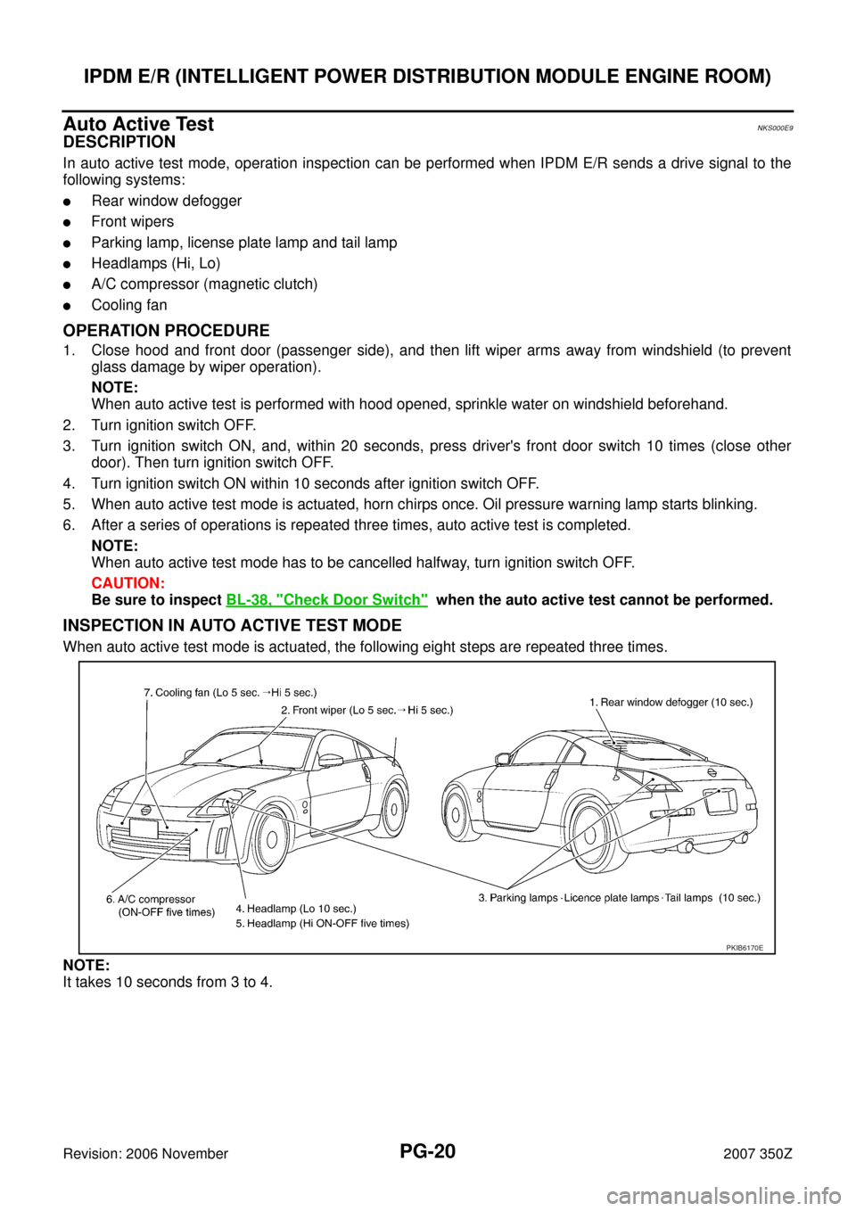
When auto active test mode is actuated, the following eight steps are repeated three times.
NOTE:
It takes 10 seconds from 3 to 4.
PKIB6170E
Page 24 of 86

PG-24
IPDM E/R (INTELLIGENT POWER DISTRIBUTION MODULE ENGINE ROOM)
Revision: 2006 November2007 350Z
IPDM E/R Power/Ground Circuit InspectionNKS000EC
1. CHECK FUSE AND FUSIBLE LINK
Make sure the following fusible links or IPDM E/R fuses are not blown.
OK or NG
OK >> GO TO 2.
NG >> If fuse or fusible link is blown, be sure to eliminate cause of malfunction before installing new fuse
or fusible link.
2. CHECK POWER SUPPLY CIRCUIT
1. Turn ignition switch OFF.
2. Disconnect IPDM E/R harness connector.
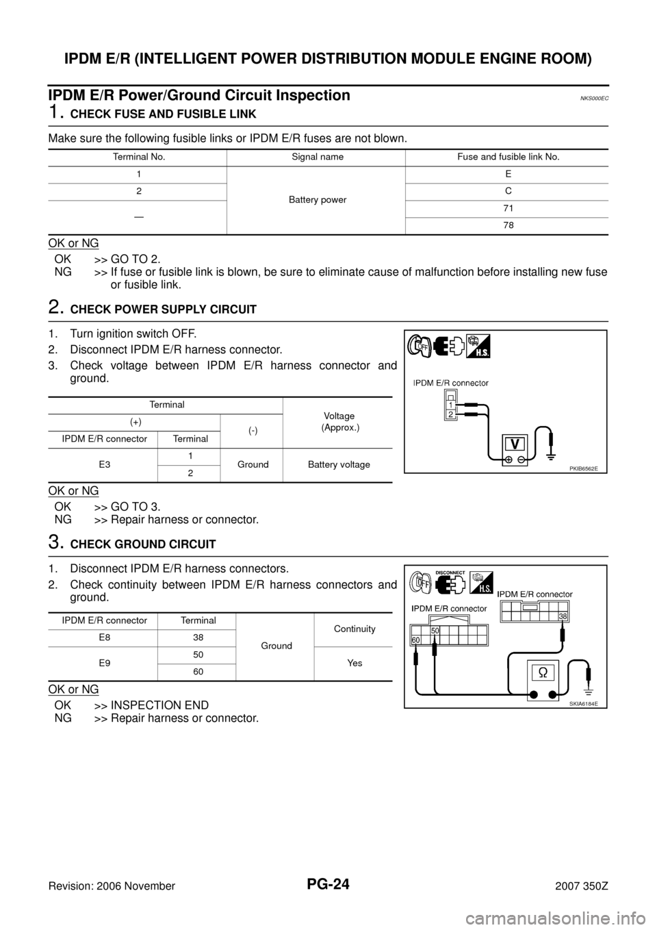
3. Check voltage between IPDM E/R harness connector and
ground.
OK or NG
OK >> GO TO 3.
NG >> Repair harness or connector.
3. CHECK GROUND CIRCUIT
1. Disconnect IPDM E/R harness connectors.
2. Check continuity between IPDM E/R harness connectors and
ground.
OK or NG
OK >> INSPECTION END
NG >> Repair harness or connector.
Terminal No. Signal name Fuse and fusible link No.
1
Battery powerE
2C
—71
78
Terminal
Vo l ta g e
(Approx.) (+)
(-)
IPDM E/R connector Terminal
E31
Ground Battery voltage
2
PKIB6562E
IPDM E/R connector Terminal
GroundContinuity
E8 38
E950
Ye s
60
SKIA6184E
Page 25 of 86
IPDM E/R (INTELLIGENT POWER DISTRIBUTION MODULE ENGINE ROOM)
PG-25
C
D
E
F
G
H
I
J
L
MA
B
PG
Revision: 2006 November2007 350Z
Inspection With CONSULT-III (Self-Diagnosis)NKS000ED
1. CHECK SELF DIAGNOSTIC RESULT
NOTE:
The details for display of the period are as follows:
�CRNT: Error currently detected with IPDM E/R.
�PAST: Error detected in the past and memorized with IPDM E/R.
Contents displayed
NO DTC IS DETECTED.FURTHER TESTING MAY BE REQUIRED.>>INSPECTION END
CAN COMM CIRC>>After print-out of the monitor items, refer to LAN-49, "
CAN Communication Signal
Chart" .
CONSULT-III displayCONSULT-III
display codeTIME
Details of diagnosis result
CRNT PAST
NO DTC IS DETECTED.
FURTHER TESTING MAY BE REQUIRED.— — — No malfunction
CAN COMM CIRC U1000××Any of or several items below have errors.
�TRANSMIT DIAG
�ECM
�BCM