Page 65 of 311
 or switch for Bluetooth
Hands-
Free Phone System (if so equipped)
4.")
1. Headlight/turn signal switch
2. Instrument brightness control switch
3. Steering wheel switch for audio control (if so
equipped) or switch for Bluetooth
Hands-
Free Phone System (if so equipped)
4. Driver supplemental air bag/Horn
5. Meters/gauges6. Cruise control main/set switch
(if so equipped)
7. Trip computer mode/setting switch
8. Wiper/washer switch
9. Center ventilator
10. Passenger supplemental air bag11. Side ventilator
12. Soft top operating switch (for Roadster
models)
13. VDC (Vehicle dynamic control) OFF switch
(if so equipped) or TCS (Traction control
system) OFF switch (if so equipped)
14. Fuel-filler door opener switch
15. Hood lock release handle
16. Fuse box
17. Tilting steering wheel lock lever
18. Ignition switch/steering lock
19. Navigation system display* or Instrument
pocket
20. Audio system/Clock
21. Rear window and outside mirror defroster
switch
22. Hazard warning flasher switch
23. Cup holder
24. Heated seat switch (if so equipped)
25. Heater/air conditioner control
26. Power outlet
*: Refer to the separate Navigation System
Owner’s Manual.
SIC3266
INSTRUMENT PANEL2-2
Instruments and controls
�
07.2.9/Z33-D/V5.0
�
Page 71 of 311

VOLT METERWhen the ignition switch is turned to the ON
position, the volt meter indicates the battery
voltage; while the engine is running, it indicates
the alternator voltage of 11 - 15 volts (normal
range
�A). However, while cranking the engine,
the volts drop below the normal range.
If the needle is not in the normal range
�A
while
the engine is running, it may indicate that the
charging system is not functioning properly.
Have the system checked by a NISSAN dealer.
TRIP COMPUTERThe display of the trip computer is situated in the
triple meter. When the ignition switch is turned
to ON, the display scrolls all the modes of the
trip computer and then shows the mode chosen
before the ignition switch is turned OFF.Switches for the trip computer are located on
the side of the combination meter panel. To
operate the trip computer, push the side of the
switches as shown above.
�A: Trip computer mode switch
�B: Trip computer setting switch
When the ignition switch is turned to ON, modes
of the trip computer can be selected by pushing
the trip computer mode switch
�A.
Each time the mode switch
�A
is pushed, the
display will change as follows:
Speed indicator→Outside air temperature
(ICY)→Distance to empty (dte)→Average fuel
SIC1955
SIC3357
SIC2997
2-8
Instruments and controls
�
07.2.9/Z33-D/V5.0
�
Page 89 of 311
illuminate. The daytime running lights illuminate
once the parking brake is released. The daytime
running lights will remain on until the ignition
switch is turned off.
TURN SIGNAL SWITCH�1
Turn signal
Move the lever up or down to signal the turning
direction. When the turn is completed, the turn
signals cancel automatically.�2
Lane change signal
To indicate a lane change, move the lever up or
down to the point where lights begin flashing.
INSTRUMENT BRIGHTNESS
CONTROLThe instrument brightness control operates
when the light switch is in the
or
position and the ignition switch is in the
ON position.
To adjust the brightness of instrument panel
lights, press the control switches located on the
left side of the meter panel. Pressing the upper
switch�A
will brighten the lights. The lower
switch
�B
will dim the lights. Repeatedly press-
ing the lower switch will turn the lights off.
SIC3316
SIC3001
2-26
Instruments and controls
�
07.2.9/Z33-D/V5.0
�
Page 92 of 311
 system on for most
driving conditions.
If the vehicle is stuck in mud or snow, the VDC
system reduces the engine output to reduce
wh")
The vehicle should be driven with the Vehicle
Dynamic Control (VDC) system on for most
driving conditions.
If the vehicle is stuck in mud or snow, the VDC
system reduces the engine output to reduce
wheel spin. The engine speed will be reduced
even if the accelerator is depressed to the floor.
If maximum engine power is needed to free a
stuck vehicle, turn the VDC system off.
To turn off the VDC system, push the VDC OFF
switch (located on the lower side of the instru-
ment panel). The
indicator light will come
on.
Push the VDC OFF switch again or restart theengine to turn on the system. See “Vehicle
Dynamic Control (VDC) system” in the “5. Start-
ing and driving” section.
The vehicle should be driven with the Traction
Control System (TCS) on for most driving con-
ditions.
If the vehicle is stuck in mud or snow, the TCS
reduces the engine output to reduce wheel spin.
The engine speed will be reduced even if the
accelerator is depressed to the floor. If maximum
engine power is needed to free a stuck vehicle,
turn the TCS off.
To turn off the TCS, push the TCS OFF switch
(located on the lower side of the instrument
panel). The
indicator light will come on.
Push it again or restart the engine to turn the
system back on.
SIC1881
SIC1967
VEHICLE DYNAMIC CONTROL
(VDC) OFF SWITCH (if so
equipped)TRACTIONCONTROL SYSTEM
(TCS) OFF SWITCH (if so
equipped)
Instruments and controls
2-29
�
07.2.9/Z33-D/V5.0
�
Page 96 of 311
CAUTION
�Do not use for anything other than
glasses.
�Do not leave sunglasses in the sun-
glasses holder while parking in direct
sunlight. The heat may damage the
sunglasses.
CARGO NETThe net located under the instrument panel
(passenger’s side) can be used to hold small
objects.
The net can be removed when necessary.
WARNING
�Do not place sharp objects in the net.
Such objects may become dangerous
projectiles and cause injury when the
vehicle is moving or if the vehicle isinvolved in a collision.
�The cargo restrained in the net must
not exceed 4 lb (2 kg) or the net may
not stay secured.
CUP HOLDERS
CAUTION
�Avoid abrupt starting and braking
when the cup holder is being used to
prevent spilling the drink. If the liquid
is hot, it can scald you or your pas-
senger.
�Use only soft cups in the cup holder.
Hard objects can injure you in an
accident.
SIC3006
Instruments and controls
2-33
�
07.2.9/Z33-D/V5.0
�
Page 103 of 311

Automatic operationTo fully open or close the window, completely
press or lift the switch and release it; it need not
be held. The window will automatically open or
close all the way. To stop the window, just press
or lift the switch on the opposite side.Auto reverse functionIf the control unit detects something caught in a
window as it moves up, the window will be
immediately lowered.
The auto reverse function can be activated when
a window is closed by automatic operation when
the ignition key is in the ON position or for about45 seconds after the ignition key is turned to the
OFF position.
Depending on the environment or driving
conditions, the auto reverse function may
be activated if an impact or load similar to
something being caught in the window
occurs.
WARNING
There are some small distances imme-
diately before the closed position which
cannot be detected. Make sure that all
passengers have their hands, etc., in-
side the vehicle before closing the win-
dow.Automatic window lowering (Roadster
models)When the soft top operating switch is pressed,
the power windows will automatically be low-
ered completely. The windows do not rise auto-
matically after the soft top open/close operation
is completed. Use the power window switches
to raise them.
AUTOMATIC ADJUSTING
FUNCTION
CAUTION
When the battery cable is removed from
the battery terminal, do not close either
of the front doors. The automatic win-
dow adjusting function will not work,
and the side roof panel/top side rail
may be damaged.
The power window has an automatic adjusting
function. When the door is being opened, the
window is automatically lowered slightly to avoid
contact between the window and the side roof
panel/top side rail. When the door is closed, the
window is automatically raised slightly.
SIC3288
2-40
Instruments and controls
�
07.2.9/Z33-D/V5.0
�
Page 119 of 311
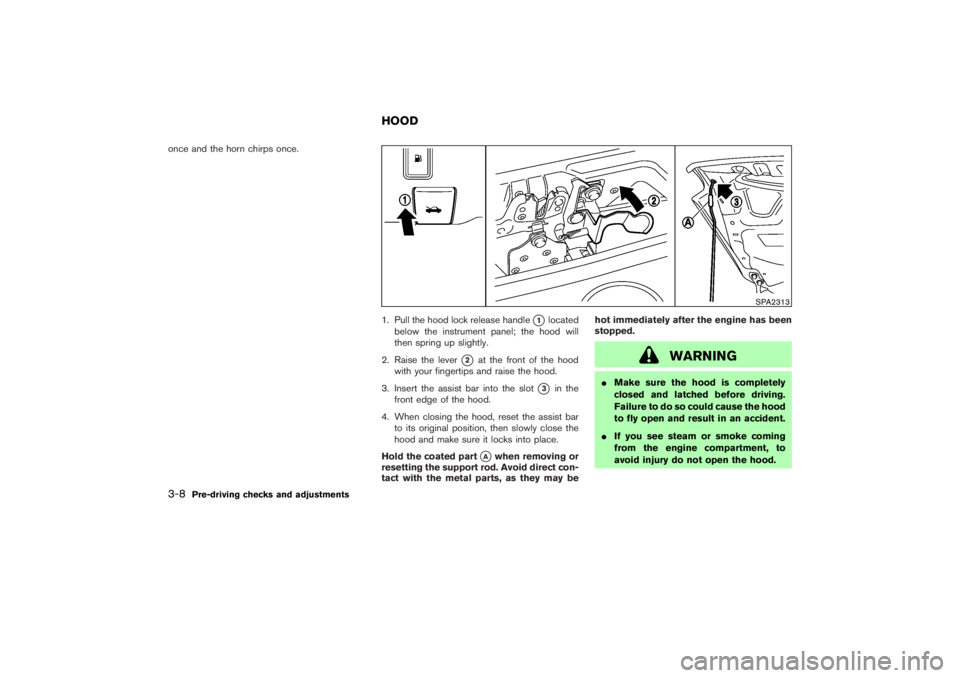
once and the horn chirps once.
1. Pull the hood lock release handle
�1
located
below the instrument panel; the hood will
then spring up slightly.
2. Raise the lever
�2
at the front of the hood
with your fingertips and raise the hood.
3. Insert the assist bar into the slot
�3
in the
front edge of the hood.
4. When closing the hood, reset the assist bar
to its original position, then slowly close the
hood and make sure it locks into place.
Hold the coated part
�A
when removing or
resetting the support rod. Avoid direct con-
tact with the metal parts, as they may behot immediately after the engine has been
stopped.
WARNING
�Make sure the hood is completely
closed and latched before driving.
Failure to do so could cause the hood
to fly open and result in an accident.
�If you see steam or smoke coming
from the engine compartment, to
avoid injury do not open the hood.
SPA2313
HOOD
3-8
Pre-driving checks and adjustments
�
07.2.9/Z33-D/V5.0
�
Page 124 of 311

3. Top side rail
4. Top latch lever
5. Soft top
6. Top storage lid
7. Trunk lid
8. Rear window
9. Rear section of th")
1. Soft top operating switch
2. Soft top indicator light (on the combination
meter)
3. Top side rail
4. Top latch lever
5. Soft top
6. Top storage lid
7. Trunk lid
8. Rear window
9. Rear section of the top
BEFORE OPERATING THE TOPThe soft top of your 350Z Roadster is electrically
operated. You can fully open or close the top
only by pressing the operating switch (on the
lower side of the instrument panel).
The soft top operating switch must be operated
under all of the following conditions:
�When the foot brake pedal is depressed.
�When the vehicle is stopped.
�When the engine is running.
CAUTION
Always keep the engine running while
operating the soft top. The top will also
operate when the ignition switch is in
the ONposition, but run the engine to
prevent a discharged battery.
Be sure to follow the operating instructions, and
all the warnings and cautions in this section.
Improper operation of the top could cause
a system malfunction, damage, or deterio-
ration of the top material and related parts.
WARNING
�Park the vehicle in a safe and level
place and apply the parking brake.
�Make sure the area is clear of ob-
stacles and there is enough clear-
ance over the top (for example, in a
garage or a covered area). More than
approximately 6.6 ft (2 m) from the
ground is required to open or close
the top safely. Otherwise, the top
may damage any objects above it
SPA2339
Interior/exterior view
SOFT TOP (Roadster models)
Pre-driving checks and adjustments
3-13
�
07.2.9/Z33-D/V5.0
�