Page 62 of 172
 - DAYTIME LIGHT SYSTEM -
Revision: 2006 November2007 350Z
NOTE:
After installation, perform aiming adjustment. Refer to LT- 6 0 , \"
Aiming Adjustment\" .
PARKING LAMP
1. Tu")
LT-62
HEADLAMP (FOR CANADA) - DAYTIME LIGHT SYSTEM -
Revision: 2006 November2007 350Z
NOTE:
After installation, perform aiming adjustment. Refer to LT- 6 0 , "
Aiming Adjustment" .
PARKING LAMP
1. Turn lighting switch OFF.
2. Remove fender protector (front). Refer to EI-21, "
FENDER PROTECTOR" .
3. Turn bulb socket counterclockwise and unlock it.
4. Remove bulb from its socket.
5. Installation is the reverse order of removal.
FRONT TURN SIGNAL LAMP
1. Turn lighting switch OFF.
2. Remove fender protector (front). Refer to EI-21, "
FENDER PROTECTOR" .
3. Turn bulb socket counterclockwise and unlock it.
4. Remove bulb from its socket.
5. Installation is the reverse order of removal.
FRONT SIDE MARKER LAMP
1. Remove headlamp. Refer to LT- 6 2 , "Removal and Installation" .
2. Replacement integral with headlamp housing assembly.
3. Installation is reverse order of removal.
CAUTION:
After installing bulb, be sure to install plastic cap and bulb socket securely to insure watertightness.
Removal and InstallationNKS004Y0
REMOVAL
1. Open the driver and front passenger window, and then disconnect the battery cable from the negative ter-
minal or remove power fuse.
CAUTION:
After the battery cables are disconnected, never open/close the driver and/or front passenger door
with the window in the full up position. The automatic window adjusting function will not work and
the side roof panel may be damaged.
2. Remove front bumper fascia. Refer to EI-14, "
FRONT
BUMPER" .
3. Remove headlamp mounting bolts.
4. Pull head lamp toward vehicle front, disconnect connector, and
remove headlamp.
INSTALLATION
Installation is the reverse order of removal.
NOTE:
After installation, perform aiming adjustment. Refer to LT- 6 0 , "
Aiming Adjustment" . Headlamp high/low beam (Xenon) : 12V - 35W (D2R)
Parking lamp : 12V - 5W
Front turn signal lamp/— : 12V - 28/8W (amber)
Front side marker lamp : LED
PKIA1865E
Headlamp mounting bolt : 6.1N·m (0.62 kg-m, 54 in lb)
Page 63 of 172
 - DAYTIME LIGHT SYSTEM -
LT-63
C
D
E
F
G
H
I
J
L
MA
B
LT
Revision: 2006 November2007 350Z
Disassembly and Assembly NKS004Y1
DISASSEMBLY
1. Turn plastic cap counterclockwise, and")
HEADLAMP (FOR CANADA) - DAYTIME LIGHT SYSTEM -
LT-63
C
D
E
F
G
H
I
J
L
MA
B
LT
Revision: 2006 November2007 350Z
Disassembly and Assembly NKS004Y1
DISASSEMBLY
1. Turn plastic cap counterclockwise, and unlock it.
2. Turn xenon bulb socket counterclockwise, and unlock it.
3. Unlock retaining spring, and remove xenon bulb.
4. Disconnect xenon bulb socket ground.
5. Remove HID control unit mounting screws.
6. Remove ground screw from HID control unit.
7. Disconnect connectors from HID control unit.
8. Pull out xenon bulb socket from head lamp housing assembly.
9. Turn parking lamp bulb socket counterclockwise and unlock it.
10. Remove parking lamp bulb from its socket.
11. Turn front turn signal lamp bulb socket counterclockwise and unlock it.
12. Remove front turn signal lamp bulb from its socket.
SKIB7543E
1. Retaining spring 2. Xenon bulb socket ground 3. Front turn signal lamp bulb
4. Front turn signal lamp bulb socket 5. Xenon bulb 6. Xenon bulb socket
7. Parking lamp bulb 8. Parking lamp bulb socket 9. Seal packing
10. Plastic cap 11. Ground screw 12. Seal packing
13. HID control unit 14. HID control unit mounting screw 15. Headlamp housing assembly
:N·m (kg-m, in-lb)
: Always replace after every disassembly.
Page 64 of 172
LT-64
HEADLAMP (FOR CANADA) - DAYTIME LIGHT SYSTEM -
Revision: 2006 November2007 350Z
ASSEMBLY
Assembly is the reverse order of disassembly.
CAUTION:
�When HID control unit is removed, reinstall it securely and avoid any looseness.
�After installing bulb, be sure to install plastic cap and bulb socket securely to insure watertight-
ness
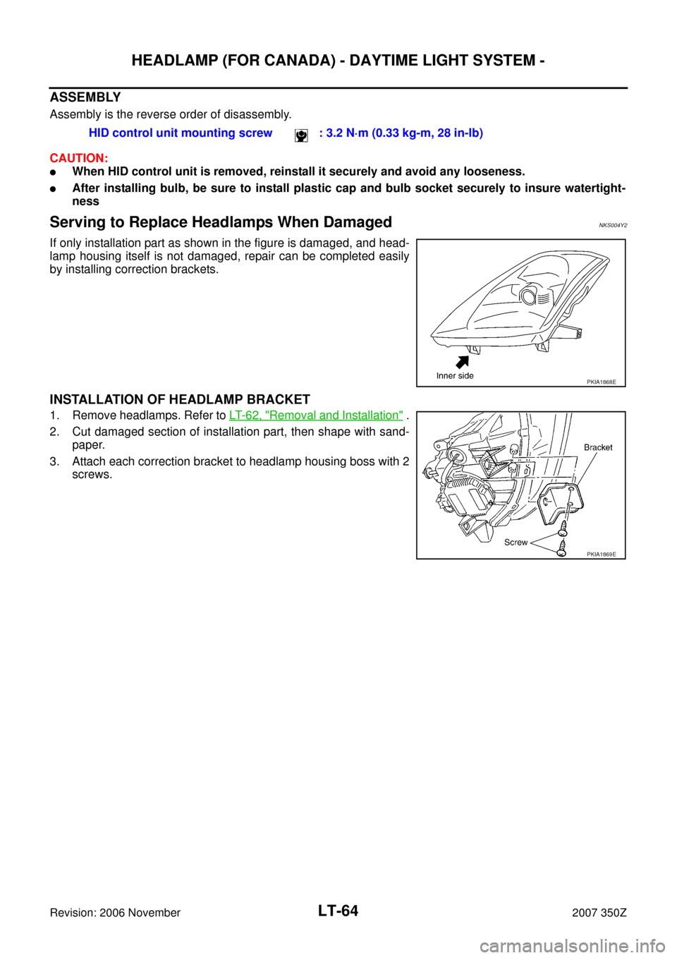
Serving to Replace Headlamps When DamagedNKS004Y2
If only installation part as shown in the figure is damaged, and head-
lamp housing itself is not damaged, repair can be completed easily
by installing correction brackets.
INSTALLATION OF HEADLAMP BRACKET
1. Remove headlamps. Refer to LT- 6 2 , "Removal and Installation" .
2. Cut damaged section of installation part, then shape with sand-
paper.
3. Attach each correction bracket to headlamp housing boss with 2
screws.HID control unit mounting screw : 3.2 N·m (0.33 kg-m, 28 in-lb)
PKIA1868E
PKIA1869E
Page 81 of 172

TURN SIGNAL AND HAZARD WARNING LAMPS
LT-81
C
D
E
F
G
H
I
J
L
MA
B
LT
Revision: 2006 November2007 350Z
Turn Signal Lamp Does Not OperateNKS004YD
1. CHECK BULB
Check bulb standard of each turn signal lamp is correct.
OK or NG
OK >> GO TO 2.
NG >> Replace turn signal lamp bulb.
2. CHECK COMBINATION SWITCH INPUT SIGNAL
CONSULT-III DATA MONITOR
1. Select "TURN SIGNAL R" and "TURN SIGNAL L" of BCM data monitor item.
2. With operating the lighting switch, check the monitor status.
CHECK COMBINATION SWITCH
Refer to LT- 9 2 , "
Combination Switch Inspection" .
OK or NG
OK >> GO TO 3.
NG >> Check combination switch (lighting switch). Refer to LT- 9 2 , "
Combination Switch Inspection" .
3. ACTIVE TEST
CONSULT-III ACTIVE TEST
1. Select "FLASHER" of BCM active test item.
2. With operating the test item, check the turn signal lamp operation.
GO TO 4
OK or NG
OK >> Replace BCM. Refer to BCS-17, "Removal and Installation of BCM" .
NG >> GO TO 4.
4. CHECK SHORT CIRCUIT
1. Turn ignition switch OFF.
2. Disconnect BCM connector and all turn signal lamp connectors.
3. Check continuity (short circuit) between BCM harness connector
and ground.
OK or NG
OK >> Replace BCM if turn signal lamps does not work after
setting the connector again. Refer to BCS-17, "
Removal
and Installation of BCM" .
NG >> Repair harness or connector.When lighting switch is
TURN RH position: TURN SIGNAL R ON
When lighting switch is
TURN LH position: TURN SIGNAL L ON
Turn signal lamp should operate.
BCM connector Terminal
GroundContinuity
RH
M9146
No
LH 45
PKIB5067E
Page 82 of 172

LT-82
TURN SIGNAL AND HAZARD WARNING LAMPS
Revision: 2006 November2007 350Z
Hazard Warning Lamp Does Not Operate But Turn Signal Lamp OperateNKS004YE
1. CHECK BULB
Make sure bulb standard of each turn signal lamp is correct.
OK or NG
OK >> GO TO 2.
NG >> Replace bulb.
2. CHECK HAZARD SWITCH INPUT SIGNAL
With CONSULT-III
1. Select "HAZARD SW" of BCM data monitor item.
2. With operating the hazard switch, check the monitor status.
Without CONSULT-III
Check voltage between hazard switch harness connector and
ground.
OK or NG
OK >> Replace BCM. Refer to BCS-17, "Removal and Installa-
tion of BCM" .
NG >> GO TO 3.
3. CHECK HAZARD SWITCH CIRCUIT
1. Turn ignition switch OFF.
2. Disconnect BCM connector and hazard switch connector.
3. Check continuity BCM harness connector and hazard switch
harness connector.
OK or NG
OK >> GO TO 4.
NG >> Repair harness or connector.When hazard switch is ON
position : HAZARD SW ON
Terminal
ConditionVo l ta g e
(Approx.) (+)
(-)
Hazard switch
connectorTerminal
M98 2 GroundHazard switch is ON 0V
Hazard switch is OFF 5V
PKIB5184E
Terminals
Continuity BCM Hazard switch
Connector Terminal Connector Terminal
M90 29 M98 2 Yes
PKIA7018E
Page 83 of 172

TURN SIGNAL AND HAZARD WARNING LAMPS
LT-83
C
D
E
F
G
H
I
J
L
MA
B
LT
Revision: 2006 November2007 350Z
4. CHECK GROUND
Check continuity hazard switch harness connector and ground.
OK or NG
OK >> GO TO 5.
NG >> Repair harness or connector.
5. CHECK HAZARD SWITCH
Check continuity hazard switch.
OK or NG
OK >> Replace BCM if turn signal lamps does not work after
setting the connector again. Refer to BCS-17, "
Removal
and Installation of BCM" .
NG >> Replace hazard switch.
Turn Signal Indicator Lamp Does Not OperateNKS004YF
1. CHECK BULB
Check bulb of turn signal indicator lamp in combination meter.
OK or NG
OK >> Replace combination meter.
NG >> Replace indicator bulb.
Bulb Replacement (Front Turn Signal Lamp)NKS004YG
Refer to LT- 2 8 , "Bulb Replacement" .
Bulb Replacement (Rear Turn Signal Lamp)NKS004YH
Refer to LT- 1 2 6 , "Bulb Replacement" .
Removal and Installation of Front Turn Signal LampNKS004YI
Refer to LT- 2 9 , "Removal and Installation" .
Removal and Installation of Rear Turn Signal Lamp NKS004YJ
Refer to LT- 1 2 7 , "Removal and Installation" .
Hazard switch
connectorTerminal
Ground Continuity
M98 1 Yes
SKIA8972E
Terminal
Condition Continuity
Hazard switch
12Hazard switch is ON. Yes
Hazard switch is OFF. No
PKIA4601E
Page 97 of 172
NKS004YT
BULB REPLACEMENT, REMOVAL AND INSTALLATION
1. Remove back door finisher upper.")
STOP LAMP
LT-97
C
D
E
F
G
H
I
J
L
MA
B
LT
Revision: 2006 November2007 350Z
High-Mounted Stop Lamp (Coupe Models)NKS004YT
BULB REPLACEMENT, REMOVAL AND INSTALLATION
1. Remove back door finisher upper. Refer to EI-48, "BACK DOOR
FINISHER" .
2. Disconnect high-mounted stop lamp connector.
3. Remove nuts and remove high-mounted stop lamp with cover
from back door. Be sure to pull toward the arrow in the figure.
4. Remove screws and remove high-mounted stop lamp assembly
from cover.
5. Installation is the reverse order of removal.
High-Mounted Stop Lamp (Roadster Models)NKS004YU
BULB REPLACEMENT, REMOVAL AND INSTALLATION
1. Turn ignition switch ON, and turn soft-top OPEN/CLOSE switch
ON.
2. When the storage lid is fully opened, soft-top OPEN/CLOSE
switch to OFF.
3. Remove battery negative cable.
4. Disconnect high-mounted stop lamp connector.
5. Remove high-mounted stop lamp.
6. Remove high-mounted stop lamp assembly from storage lid.
7. Installation is the reverse order of removal.
Stop LampNKS004YV
BULB REPLACEMENT
Refer to LT- 1 2 6 , "Bulb Replacement" .
REMOVAL AND INSTALLATION
Refer to LT- 1 2 7 , "Removal and Installation" . High-mounted stop lamp : LED
PKIA1873E
High-mounted stop lamp : LEDPKIA3697E
Page 102 of 172
LT-102
BACK-UP LAMP
Revision: 2006 November2007 350Z
Bulb ReplacementNKS004YX
Refer to LT- 1 2 6 , "Bulb Replacement" .
Removal and InstallationNKS004YY
Refer to LT- 1 2 7 , "Removal and Installation" .